

-
Leon Zhang sales consultant
-
Email: zxl635973785@gmail.com
-
Phone/WhatsApp: +86 13655813266
Earth Fault Relay: Complete Guide to Protection, Applications, Settings, and Troubleshooting
Earth fault ranks among the most frequent faults occurring in power systems.
Failure to detect earth faults in a timely manner may lead to severe consequences including equipment damage, burnt cables, transformer malfunctions, arc flash incidents and unexpected power outages.
For this reason, earth fault relays serve as essential protective devices widely deployed in utility substations, industrial plants, solar power stations, wind farms and commercial buildings.
What is an Earth Fault Relay?
An earth fault relay is a protective relay that detects current flowing from a phase conductor to earth and sends an alarm or trip command when the measured earth-fault current exceeds a preset threshold.
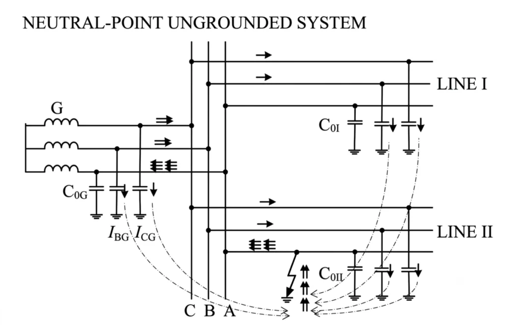
Earth fault relay detects single-phase-to-earth faults and insulation degradation by measuring zero-sequence current (3I₀) or zero-sequence voltage (3U₀), depending on the system grounding method — current-based in solidly or low-resistance grounded systems, and voltage-based in unearthed or arc-suppression-coil-grounded systems.
Upon pickup, it issues an alarm, initiates a time delay, and trips the circuit breaker if the fault persists, while recording fault data for analysis. It is widely applied in protection for feeders, motors, transformers, generators, and distribution lines, especially in medium and low voltage systems with unearthed, arc-suppression-coil-grounded, or low-resistance-grounded neutrals.
How Earth Fault Relay Works?
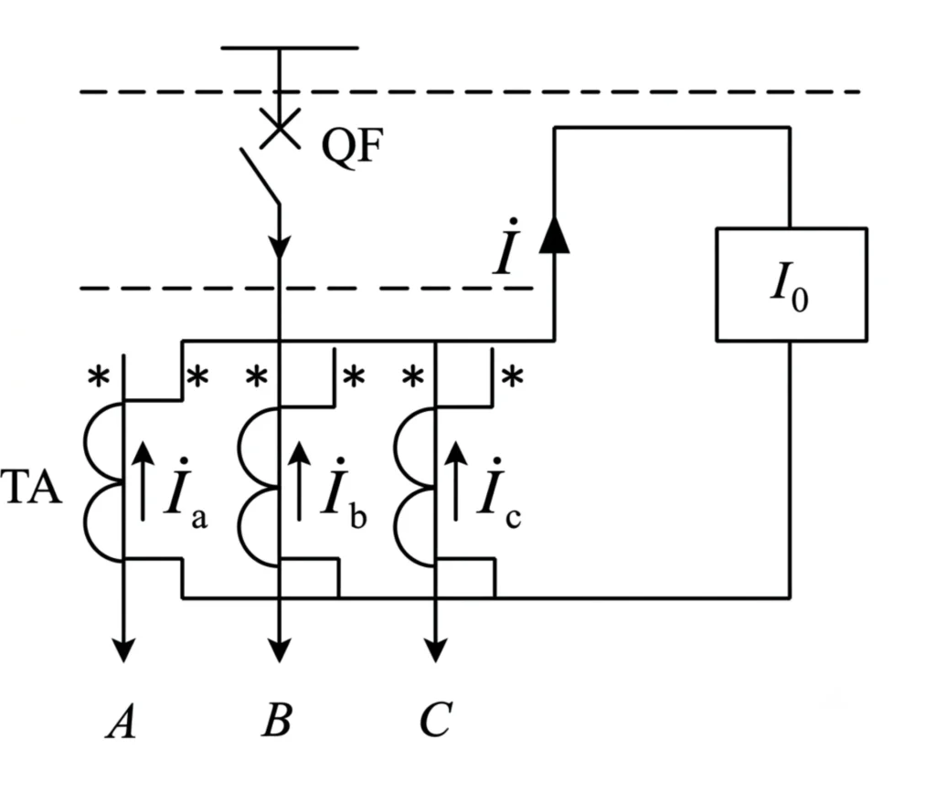
Earth fault protection relay monitors residual current via current transformers. Under normal operating conditions, the vector sum of three-phase currents equals zero, with no residual current flowing through the relay.
Working Principle: Residual Current Method
Normal operating condition
In normal operation, the three-phase currents are balanced, and their vector sum equals zero. No residual current or zero-sequence voltage is present. The relay remains inactive and continuously monitors the system for any abnormality.
Normal condition:
Ia+Ib+Ic=0
Earth fault condition
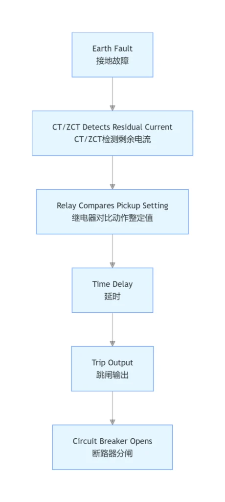
When a phase conductor comes into contact with earth, the system symmetry is broken. An unbalanced current flows to earth, creating a residual current (3I₀) or zero-sequence voltage (3U₀), indicating the presence of a fault.
Residual current detection
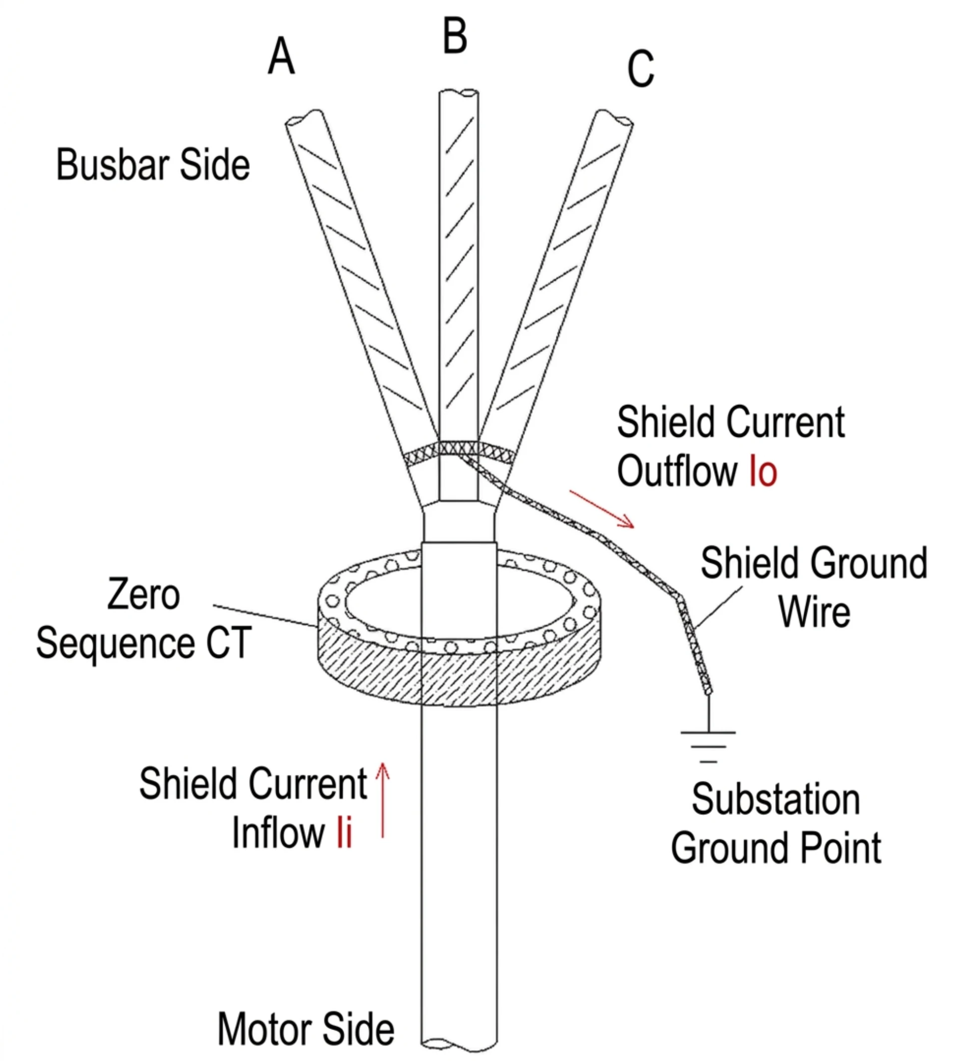
The relay measures residual current using the vector sum of the three-phase currents (Ia + Ib + Ic) via a core-balance current transformer, or measures zero-sequence voltage from the open-delta winding of a voltage transformer. These signals serve as the input to the relay.
Earth fault occurs:
Ia+Ib+Ic≠0→ Residual current generated.
Relay pickup and trip
Once the measured residual current or voltage exceeds the preset threshold, the relay picks up. It immediately issues an alarm and starts a time delay. If the fault persists beyond the delay setting, the relay outputs a trip command to the circuit breaker.
Once Residual Current > Setting Value, the relay operates.
Circuit breaker operation
Upon receiving the trip command, the circuit breaker opens its contacts, isolating the faulty circuit from the system. This clears the fault and protects downstream equipment. The breaker status can be monitored via auxiliary contacts.
Earth Fault Relay Circuit Diagram
Proper earth fault relay connection is essential to ensure correct fault detection and reliable operation.
Types of Earth Fault Relays
Overcurrent Earth Fault Relay — 50N/51N
Detects earth faults by measuring residual current. 50N provides instantaneous tripping for severe faults, while 51N offers time-delayed tripping with inverse-time characteristics for coordination with downstream protection. Suitable for general earth fault protection in feeders and distribution networks.
Sensitive Earth Fault Relay — SEF
Designed to detect very low earth fault currents (as low as mA级别), typically using a core-balance CT for high sensitivity. Ideal for high-impedance grounding systems where fault currents are minimal, providing early warning of insulation degradation before major faults develop
Directional Earth Fault Relay — 67N
Determines the fault direction by comparing the phase angle between residual current and residual voltage. Only operates when the fault is in the forward direction. Essential for ring main networks and parallel feeders where fault current can flow in both directions, enabling selective fault isolation.
Restricted Earth Fault Relay — 64REF
Protects a specific zone within transformer windings by comparing currents at both ends of the protected zone. Under normal or external fault conditions, currents balance; internal earth faults create a differential current that trips the breaker. Provides high-speed, highly sensitive protection for transformer internal winding earth faults.
Stator Earth Fault Relay — 64G
Specifically designed for generator stator winding earth fault protection. Typically installed at the neutral side of the generator, it measures the current flowing through the neutral grounding connection. Detects stator winding insulation failures and trips to prevent severe generator damage. Often used in conjunction with 100% stator earth fault protection schemes for complete coverage.
Summary
| ANSI Code | Name | Function Description |
|---|---|---|
| 50N | Instantaneous overcurrent earth protection (N = neutral/earth) | No time delay tripping for severe earth faults |
| 51N | Definite-time / inverse-time overcurrent earth protection | Time-delayed coordination for general earth faults |
| SEF | Sensitive earth fault protection | Detects very low earth fault currents (mA level) for high-impedance grounded systems |
| 67N | Directional earth protection | Determines fault direction for ring main or complex distribution networks |
| 64REF | Restricted earth fault protection | For internal transformer winding earth faults, with protection zone limited to the winding range |
| 64G | Generator stator earth protection | Specifically for generator stator winding earth faults |
Earth Fault Relay Setting Guide
Earth Fault Pickup Setting
The pickup setting defines the minimum residual current level that will trigger the relay. It must be set above the maximum expected unbalance current during normal operation to avoid nuisance tripping, while remaining low enough to detect genuine earth faults. Typical settings range from 10% to 40% of the rated current, depending on system grounding and load characteristics.
Time Delay Setting
The time delay setting determines how long the relay waits after pickup before issuing a trip command. This allows downstream protection devices to operate first for faults closer to the load, achieving selective coordination. Delay characteristics can be definite-time (fixed delay) or inverse-time (delay inversely proportional to fault current magnitude).
50N/51N Setting
50N setting defines the instantaneous pickup threshold for high-magnitude earth faults, with no intentional time delay, typically set above the maximum through-fault current to avoid unwanted operation. 51N setting defines the time-current curve for delayed earth fault protection, coordinated with downstream devices. The 51N curve selection (e.g., IEC standard inverse, very inverse, extremely inverse) depends on the system requirements and coordination study.
Sensitive Earth Fault Setting
SEF settings are designed for detecting very low earth fault currents in high-impedance grounded or unearthed systems. The pickup value is typically set in the milliamp range (e.g., 50mA to 5A) using a core-balance CT. Time delay is often set longer than standard overcurrent protection to allow for transient disturbances and to ensure stability.
Directional Earth Fault 67N Setting
67N setting involves configuring both the pickup threshold and the directional characteristic. The relay must be set with a reference polarizing voltage (3U₀) and a characteristic angle (RCA) to define the forward and reverse zones. Proper setting ensures the relay operates only for faults in the forward direction and remains stable for reverse faults or load unbalance.
CT Ratio and Relay Setting
The CT ratio directly affects the relay setting calculations. The relay pickup value in primary amperes must be converted to secondary amperes using the CT ratio (e.g., 400/5A). The relay settings are entered in secondary values. Proper CT sizing is critical — too small a CT may saturate during high faults, while too large a CT reduces sensitivity for low-level faults.
Earth Fault Relay Coordination
Coordination ensures that the relay closest to the fault operates first, isolating the minimum section of the network. This is achieved by grading pickup currents and time delays between upstream and downstream relays. The coordination study involves plotting time-current curves (TCC) and ensuring margins between successive devices, typically 0.3 to 0.5 seconds, to maintain selectivity.
Worked Setting Example
A worked example demonstrates the complete setting calculation process. For an 11kV feeder with 400/5A CTs and 100A maximum load: set earth fault pickup at 20% of rated CT primary current = 80A primary (1A secondary). Set 51N using IEC standard inverse curve with a time dial of 0.1 to achieve 0.4s coordination margin with downstream relay. Set 50N instantaneous at 400A primary (5A secondary).
The example verifies sensitivity and coordination through TCC plotting and fault current calculations.
How to Test an Earth Fault Relay
| Test Item | Description |
|---|---|
| Visual inspection | Check relay appearance, terminal tightness, and CT/VT wiring against the approved diagram. Verify nameplate ratings match specifications. Any abnormalities must be corrected before further testing. |
| CT polarity check | Confirm CT secondary leads are connected with correct polarity to the relay to avoid misoperation or failure to operate. When primary current flows P1→P2, secondary current should flow S1→S2 through the relay. All phase CTs and zero-sequence CT must be verified. Reversed connections must be corrected before energization. |
| Pickup current test | Verify relay operates correctly at the preset current threshold. Inject current and gradually increase until pickup. Measured value should be within ±5% of the setting. Test each phase and earth fault input separately. |
| Definite-time test | Verify relay trips at a fixed time delay when current exceeds the setting. Inject current above the pickup threshold and measure time from application to trip output. Tolerance should be ≤ ±50ms or ±5% of setting. |
| Inverse-time test | Verify trip time conforms to the selected time-current curve (e.g., IEC standard inverse). Inject currents at 2×, 5×, and 10× pickup and measure trip times. Compare against theoretical curve to ensure correct coordination. |
| Trip output test | Verify relay correctly energizes the trip circuit when trip conditions are met. Force relay operation and monitor trip contact output. Confirm trip signal at the circuit breaker trip coil and SCADA to verify entire trip circuit integrity. |
| Secondary injection test | Comprehensive test by injecting simulated signals into relay secondary terminals to verify pickup values, time delays, directional characteristics, and trip outputs. Compare results against setting sheets. This is the most common and effective method for commissioning and maintenance. |
| 67N directional test | Verify directional earth fault relay correctly identifies fault direction based on phase angle between residual current (3I₀) and residual voltage (3U₀). Inject current and voltage signals with adjustable phase angles. Confirm forward tripping and reverse blocking, and verify characteristic angle (RCA) setting. |
Difference between earth fault relay and overcurrent relay
| Comparison Point | Overcurrent Relay (50/51) | Earth Fault Relay (50N/51N) |
|---|---|---|
| Monitored Current | 3-phase line/phase current | Residual / zero-sequence earth current |
| Protected Faults | Phase-phase short circuit, overload, severe high-current earth faults | Phase-earth leakage, insulation breakdown, all ground faults (no phase-phase protection) |
| Sensitivity | Low (high pickup setting) | High (detects small earth leakage) |
| Typical Setting | 125%–200% of full load current | 5%–30% of full load current |
| CT Connection | Individual CT per phase | Residual summation CT / Zero-sequence CT (ZCT) |
| Core Function | Protect equipment from overload & phase short faults | Protect system & personnel from earth/ground leakage faults |
Common Causes of Earth Faults
Cable Insulation Deterioration
Undetected residual leakage gradually triggers cable earth fault and accelerates insulation failure, eventually leading to costly equipment damage and unexpected plant outages.
Moisture and Water Ingress
Moisture and water ingress frequently occurs at solar farms, outdoor substations and wind power plants, triggering hidden leakage current that evolves into cable earth fault and eventually causes severe insulation failure.
Aging Electrical Equipment
Aging Electrical Equipment including Switchgear, Transformers and Motors, alongside moisture and water ingress at solar farms, outdoor substations and wind power plants, produces invisible leakage current, gradually leading to cable earth fault and permanent insulation failure.
Mechanical Damage
Mechanical Damage from excavation, rodent damage and vibration, aging electrical equipment including switchgear, transformers and motors, as well as moisture and water ingress at solar farms, outdoor substations and wind power plants, all create hidden leakage current, progressing into cable earth fault and irreversible insulation failure.
Incorrect Wiring
Fault Description: Improper cable connection, reversed wiring or neutral-earth misconnection causes false earth faults and nuisance tripping of earth protection. Inspect primary and secondary wiring and correct wrong connections.
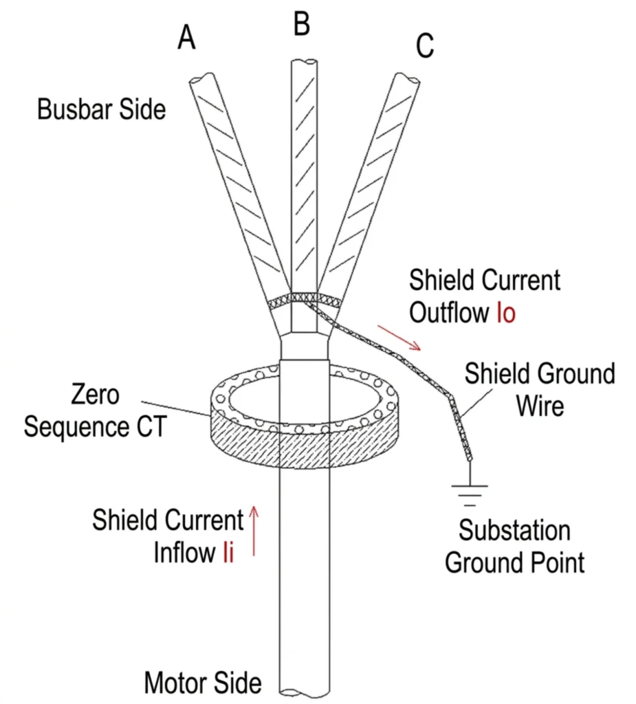
Earth Fault Relay Applications
Earth Fault Relay for Transformer
64REF restricted earth fault protection is used to detect internal winding faults, with neutral-side 51N overcurrent earth fault as backup. The relay is connected to the neutral CT. Upon internal earth fault, it rapidly trips circuit breakers on both HV and LV sides to minimize winding damage and fire risk.
Earth Fault Relay for Generator
64G stator earth fault protection is installed at the generator neutral point, providing high-sensitivity detection of stator winding earth faults. It is often combined with third-harmonic or neutral voltage schemes to achieve 100% winding coverage, preventing small faults from escalating and causing core damage.
Earth Fault Relay for Motor
50N/51N overcurrent earth fault protection is typically used, with leakage detection via core-balance CT or residual connection from three-phase CTs. Settings must consider motor starting current to avoid nuisance tripping. SEF may be applied in high-resistance or unearthed systems for reliable detection of low-magnitude fault currents.
Earth Fault Relay for Feeder
51N overcurrent earth fault protection is mainly used, utilizing residual current from three-phase CTs with delayed inverse-time coordination. For ring main or complex systems, 67N directional earth fault protection is required to discriminate fault direction and achieve selective tripping, ensuring only the faulty section is isolated.
Earth Fault Relay for Solar
On the AC side, 50N/51N protection is applied at the inverter output or transformer LV side. On the DC side, dedicated RCM monitors leakage between arrays and earth. 67N directional protection may be used in MV collection systems. In unearthed or high-resistance grounded configurations, SEF is commonly used for early insulation degradation warning.
How to Select an Earth Fault Relay
System Voltage
Earth fault relay type is determined according to system voltage:
LV System: Adopt standard 50N/51N overcurrent earth fault relay for general distribution, SEF for equipment with high insulation requirement.
MV System: Configure SEF sensitive earth fault relay plus 67N directional earth fault relay for ring networks & renewable collection lines.
HV System: Apply dedicated directional earth protection matched with substation primary equipment.
Grounding Method
Four Main Neutral Earthing Configurations
Solid Grounded System
Standard ANSI 50N/51N overcurrent earth fault relays are the primary choice. High earth-fault current ensures stable and dependable fault detection.
Resistance Grounded System
A combination of 51N plus SEF sensitive earth fault protection is adopted to detect both heavy short-circuit earth faults and minor leakage faults.
Petersen Coil (Arc Suppression Coil) Grounded System
SEF high-sensitivity earth fault relay is essential, as residual fault current remains extremely low under ground fault conditions.
Ungrounded System
SEF paired with 67N directional earth fault relay is recommended to identify faint insulation degradation and subtle earth faults.
Summary
The selection of earth fault relays is determined by the system’s neutral grounding scheme; the application scope of SEF and 67N varies greatly across different earthing types.
Communication Requirements
Modern projects support multiple mainstream communication protocols for earth fault relays:
- Modbus RTU
- Modbus TCP
- IEC 61850
- IEC 60870-5-104 (IEC 104)
- DNP3
The earth fault protection relays are equipped with versatile communication interfaces to meet modern automation demands. Data including fault records, measured values, protection setting parameters and relay status can be uploaded to SCADA or central control system via above protocols.
Integration with SCADA
Remote monitoring capability has become a key concern for most customers. Protection relays upload real-time operating data, fault alerts and protection parameter values to SCADA systems via standard communication protocols, enabling centralized remote supervision and fault diagnosis from control rooms.
Modern Features of Digital Earth Fault Relays
| Feature Name | Detailed Function Description |
|---|---|
| Self-Diagnostics | Real-time device health monitoring |
| Event Recording | Full event log for fault and abnormal operation history |
| Fault Waveform Capture | High-resolution oscillography function to capture fault waveforms |
| Multiple Protection Functions | Built-in ANSI standard protection elements:• 50/51: Phase overcurrent protection• 50N/51N: Neutral earth fault overcurrent protection• 67N: Directional neutral overcurrent protection• 49: Thermal overload protection for winding• 46: Negative sequence overcurrent protection |
| IEC 61850 Communication | Fully compliant for digital substation applications |
| Cybersecurity Features | Meets international cybersecurity standards:• IEC 62351• NERC CIP |
Conclusion
Proper selection of an Earth Fault Relay protects equipment, improves overall system reliability, minimizes downtime, and fulfills the requirements of modern smart grid and renewable energy projects.
For projects requiring long-term stable operation and remote monitoring, digital protective relays equipped with Multi-Protocol Communication, IEC 61850 Compatibility, Fault Recording and Advanced Earth Fault Detection are highly recommended.
FAQ
What is an earth fault relay?
A protective device that detects earth faults by measuring residual current or zero-sequence voltage, and issues an alarm or trip command to isolate the faulty circuit.
What is the ANSI code for an earth fault relay?
There is no single code. Common codes include 50N (instantaneous), 51N (time-delayed), 67N (directional), 64REF (restricted), and 64G (stator earth fault).
What is the difference between 50N, 51N and 67N?
50N trips instantly for severe faults. 51N provides time-delayed tripping for coordination. 67N operates only for forward-direction faults in ring main or parallel systems.
What is the difference between earth fault and ground fault?
They are essentially the same. “Earth fault” is IEC terminology; “ground fault” is ANSI/NEC terminology. Both refer to a phase-to-earth/ground connection.
What CT is used for earth fault protection?
Three types: three-phase CTs in residual connection, core-balance CT (zero-sequence CT), or neutral CT installed on the neutral-to-earth connection.
How do you calculate earth fault relay settings?
Set pickup above normal unbalance but below minimum fault current. Select time delay based on coordination. Convert primary values to secondary using CT ratio. Verify via TCC plotting.
What is a sensitive earth fault relay?
A relay designed to detect very low earth fault currents (mA level) using a core-balance CT, used in high-resistance or unearthed systems for early insulation degradation warning.
What is the difference between earth fault relay and RCD?
Earth fault relays are for industrial systems with adjustable settings, SCADA, and IEC 61850. RCDs are for residential/commercial use with fixed settings, no communication, and focus on personnel shock protection.
How to check earth fault relay?
Inspect wiring and CT connection, verify settings, perform secondary injection test and check recording & communication to complete earth fault relay inspection.
How to connect earth fault relay?
Connect CT residual circuit to relay input terminals, confirm correct polarity then wire auxiliary trip and communication circuits.
How to set earth fault relay?
Set pickup current and time delay per system parameters for selective coordination.
How to test directional earth fault relay?
Inject phase-shifted test current to verify operating direction and pickup threshold of directional earth fault relay.
Where earth fault relay is employed?
Installed on distribution panels, transformer feeders, motor circuits and renewable energy collection feeders.
Why earth fault relay trip?
It trips due to actual earth fault, improper setting, wrong CT polarity, cable leakage or motor starting inrush current.
Related Products
Low Current Earth Fault Line Selector



About Author

Hello, I'm Leno Zhang. I have 15 years of experience in the power relay protection industry with extensive pre-sales and after-sales project experience. Our company specializes in various complete sets of relay protection and automation equipment. I can assist customers in solving all practical on-site project challenges and provide optimal integrated solutions.
Tell Us Your Requirement
High Quality
Stable performance, reliable design, ensuring safe operation for power system protection and grid stability.
Fast Delivery
Timely delivery to support your urgent orders and project schedules efficiently and professionally at any time.
Best Warranty
Professional Warranty: Reliable after-sales support for stable relay protection and long-term customer satisfaction.