

-
Leon Zhang sales consultant
-
Email: zxl635973785@gmail.com
-
Phone/WhatsApp: +86 13655813266
What Are Protective Relays? Types, Functions and Working Principle
Protective relays are the core safety devices of modern power systems. They continuously monitor electrical parameters, identify abnormal conditions, and trigger immediate isolation actions to protect generators, transformers, transmission lines, motors, and distribution equipment.
This article breaks down the working principle, core types, key settings, practical applications, and selection criteria of protective relays, covering core knowledge of power system protective relaying, with industry‑standard specifications and real operational logic, helping power system engineers and project stakeholders make informed device specification and system design decisions.
What Is a Protective Relay?
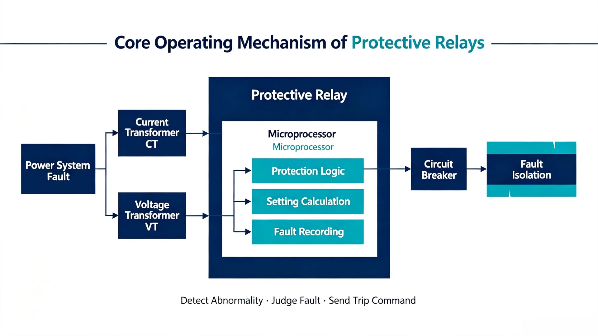
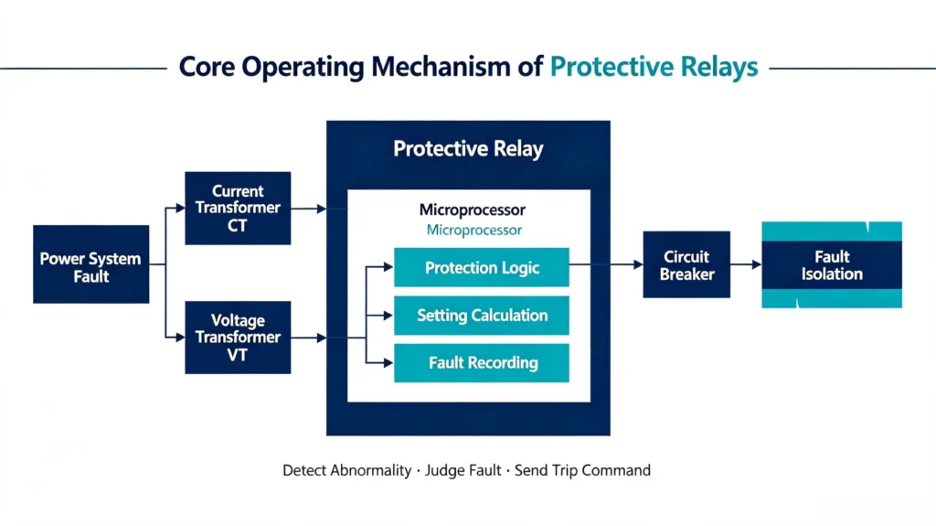
A protective relay is a microprocessor or electromechanical‑based monitoring and protection device dedicated to power system safety. As introduced in Fundamentals of Modern Protective Relaying, it acts as the “decision‑making brain” of power system protection, paired with current transformers (CTs), voltage transformers (PTs/VTs), and circuit breakers to form a complete protection loop.
Core Functions
- Real-time monitoring of electrical operating parameters
Key Monitored Electrical Parameters
Protective relays track critical system indicators to capture deviations from normal operating conditions:
- Current, voltage, frequency
- Power, power factor, phase angle, impedance
- Differential current, residual zero-sequence current
Core Protection Logic Sequence
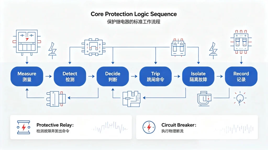
All protective relays follow a unified standard workflow: Measure → Detect → Decide → Trip → Isolate → Record
Note: Relays only detect faults and issue commands; circuit breakers execute physical circuit interruption. This division of labor is the foundation of power system protection design.
How Do Protective Relays Work? Step-by-Step Working Principle
This is the core operational mechanism of protective relays, applicable to all modern numerical relay models compliant with IEC and IEEE standards.
Step 1: Collect Field Electrical Signals
CTs step down high system current to low measurable secondary current (standard 1A/5A), and PTs/VTs convert high system voltage to standard low signal voltage. These sensors transmit real-time system operating data to the protective relay.
Step 2: Signal Conversion and Processing
The relay performs signal conditioning, filters interference noise, and converts analog electrical signals to digital data via an internal ADC (Analog-to-Digital Converter). Numerical relays further process data through built-in digital signal processing (DSP) algorithms to ensure high-precision measurement.
Step 3: Compare Measured Data With Predefined Settings
The relay compares real-time operating data with user-configured threshold parameters, including pickup current, voltage/frequency limits, time delay, directional logic, and differential protection thresholds. Setting accuracy directly determines protection reliability.
Step 4: Intelligent Protection Decision-Making
- Normal condition: Measured values within thresholds → No action, system operates normally
- Minor abnormality: Slight parameter deviation → Trigger local/remote alarm for early warning
- Fault condition: Severe parameter over-limit → Execute trip protection logic
Step 5: Output Trip Signal and Isolate Fault
When a confirmed fault is detected, the relay’s internal output contacts close, energize the circuit breaker trip coil, and drive the breaker to open. This isolates the faulty equipment/feeder within milliseconds to prevent fault expansion.
Step 6: Record Fault Data for Post-Analysis
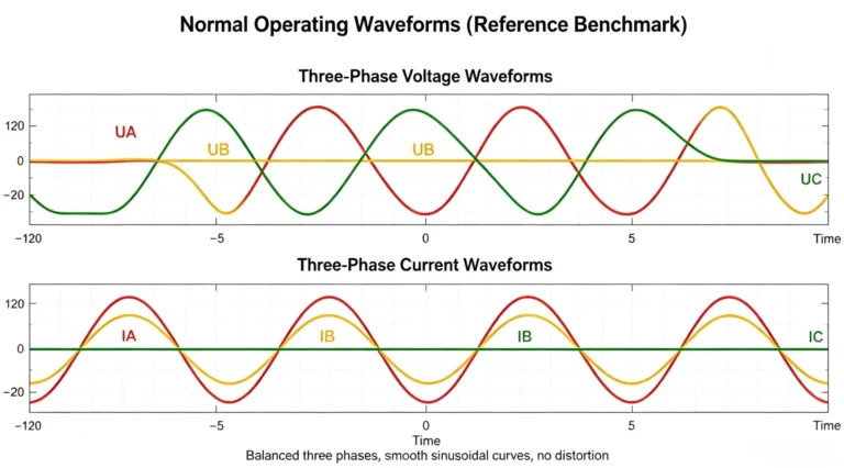
Modern numerical relays automatically record fault timestamps, event logs, waveform oscillography, and disturbance data. These records help EPC engineers and project owners analyze fault causes, optimize protection settings, and improve system operation stability.
Practical Working Example: Overcurrent Protection
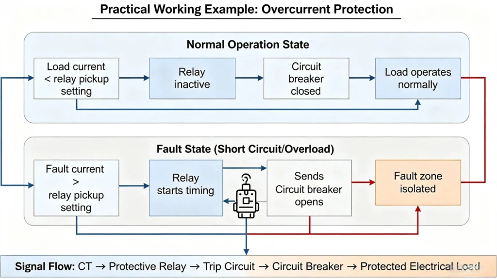
Overcurrent protection is the most basic and widely used protection scheme for feeders, motors, and distribution lines, with intuitive and verifiable operating logic.
Normal Operation State: Load current < relay pickup setting → Relay remains inactive, circuit breaker closed, load operates normally.
Fault State (Short Circuit/Overload): Fault current > relay pickup setting → Relay starts timing (instantaneous protection skips delay) → Sends trip command → Circuit breaker opens → Fault zone isolated.
Full Fault Response Process in Power Systems
- Fault Detection: Capture short circuit, overcurrent, ground fault, over/undervoltage and other abnormal states
- Fault Identification: Confirm fault phase, fault type, and whether the fault is inside/outside the protected zone
- Protection Judgment: Verify threshold values, directional logic, and time delay coordination
- Fault Isolation: Circuit breaker trips to cut off the faulty branch
- Data Recording & Recovery: Generate alarms, save fault data, and support system recovery and post-fault optimization
Main Types of Protective Relays (Industrial Classification)
Different types of protective relays correspond to targeted protection scenarios, covering full protection requirements of power generation, transmission, distribution, and industrial loads.
| Relay Type | Core Protection Function | Typical Application Scenarios |
|---|---|---|
| Overcurrent Relay (ANSI 50/51) | Instantaneous/time-delayed overcurrent protection for overload and short-circuit faults | Distribution feeders, motors, low-voltage lines |
| Earth/Ground Fault Relay (ANSI 50N/51N) | Detect zero-sequence/residual current for ground fault protection | Substation equipment, underground cables, industrial systems |
| Differential Relay (ANSI 87) | Judge internal faults via current difference comparison | Transformers, generators, busbars (core main protection) |
| Distance Relay (ANSI 21) | Judge fault location via line impedance measurement | High-voltage transmission lines |
| Voltage/Frequency Relay (ANSI 27/59/81) | Over/under voltage and over/under frequency protection | Generators, grid-connected systems, renewable energy stations |
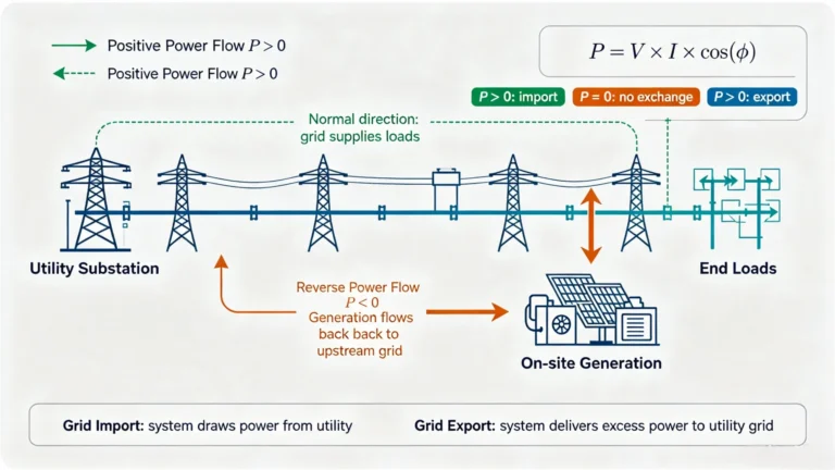
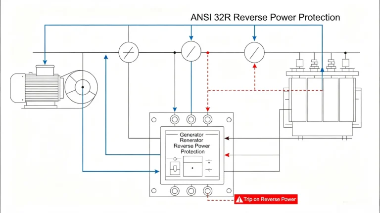
| Reverse Power Relay (ANSI 32) | Prevent reverse power transmission damage | Generators, solar PV and energy storage systems |
| Motor/Generator Special Relay | Multi-functional dedicated protection for rotating equipment | Industrial large motors, power station generators |
Three Generations of Protective Relay Technology
Electromechanical Relays
Traditional mechanical structure relays with simple principles and strong anti-interference ability. However, they have low accuracy, slow response, single function, and no data recording capability, gradually phased out in new EPC projects.
Static Relays
Composed of discrete electronic components, featuring faster operation and higher accuracy than electromechanical products. Limited by fixed logic, they cannot support remote monitoring and multi-function integration.
Numerical Protection Relays (Mainstream Current Choice)
Microprocessor-based intelligent relays compliant with IEC 60255 and IEEE C37 series standards. They integrate protection, measurement, control, communication, and data recording in one device, supporting flexible setting adjustment, remote monitoring, and self-diagnosis. They are the standard configuration for modern substations, industrial power systems, and renewable energy projects.
Protective Relay Settings: Key Rules for Engineering Implementation
Relay setting is the core of protection system commissioning. Unreasonable settings directly cause two major engineering problems: nuisance tripping (over-sensitive) and protection failure (insensitive).
Core Setting Parameters
- Pickup threshold: The critical value to trigger protection action, calibrated according to system rated parameters and fault current calculation
- Time delay: Match protection grading coordination to avoid cascading tripping of upper and lower equipment
- Characteristic curve: Support standard IEC and IEEE inverse-time curves for scenario-adaptive protection
- Directional/differential logic: Eliminate external fault interference and ensure accurate zone protection
Core Engineering Principle
All settings must complete inter-device coordination verification to ensure hierarchical protection action priorities and improve overall system safety and stability.
Protective Relay vs Circuit Breaker: Clear Functional Division
Many project owners confuse the two core devices; their functional division is fixed in power system engineering:
| Device | Core Role | Operating Attribute |
|---|---|---|
| Protective Relay | Detect faults, judge conditions, and issue trip commands | Decision-making device (no physical breaking capability) |
| Circuit Breaker | Physically open/close the circuit to isolate faults | Executive device (no fault judgment capability) |
| CT/PT | Collect and convert field electrical signals | Sensing and sampling device |
Core Takeaway: The relay detects and commands; the circuit breaker interrupts.
Common Application Scenarios of Protective Relays
Protective relays cover the full scenario requirements of new energy, industrial power, and power grid EPC projects:
- Substations and high/medium/low voltage distribution systems
- Power transformers, generators, and busbar systems
- Transmission lines and distribution feeders
- Industrial large motor and mechanical equipment
- Solar PV stations, wind power plants, and battery energy storage systems
Modern Numerical Relay Capabilities: Beyond Basic Protection
Traditional relays only complete protection actions, while modern numerical relays expand to five-in-one integrated capabilities, meeting the intelligent operation and maintenance needs of modern EPC projects:
- Precision electrical measurement and real-time data upload
- Local/remote intelligent control
- Standard communication (Modbus, Ethernet, IEC 61850)
- Complete event/fault waveform recording
- Real-time self-diagnosis and equipment health monitoring
It realizes the upgrade from single protection device to intelligent monitoring terminal for power systems.
Standard Relay Testing & Commissioning Methods
To ensure on-site operational reliability, relays must complete standardized testing before project commissioning, complying with IEC and IEEE test specifications:
- Secondary injection testing: Verify protection threshold and operating time accuracy (conventional core test)
- Primary injection testing: Simulate real field fault conditions to verify overall protection loop performance
- Trip output & communication testing: Confirm breaker linkage and remote data transmission stability
- End-to-end testing: Verify the overall coordination of the entire protection system
Common On-Site Faults & Solutions
Summarized from EPC project site experience, the most frequent relay problems and root causes:
- Nuisance tripping: Over-sensitive setting, CT interference, or unreasonable curve matching
- Failure to trip: Setting threshold too high, CT polarity error, or trip circuit fault
- System coordination disorder: Mismatched time delay between upper and lower protection devices
- Communication failure: Protocol mismatch or on-site wiring error
How to Select a Qualified Protective Relay for Your Project
For EPC contractors and project owners, relay selection must match project voltage level, load type, and intelligent operation and maintenance requirements, focusing on 10 core indicators:
- Matching system voltage and rated current
- Complete required protection functions (ANSI standard functions)
- Compatible CT/PT secondary input parameters
- Sufficient binary input/output ports
- Standard communication protocols for SCADA integration
- High-precision fault recording and event logging
- Compliance with IEC/IEEE international standards
- Strong anti-interference and surge withstand capability
- Simple on-site installation and debugging
- Stable after-sales technical support
FAQ About Protective Relays
1. How does a protective relay detect power system faults?
It collects real-time electrical data via CT/PT, compares measured values with preset standard thresholds, and identifies faults through built-in professional protection algorithms.
2. Can one numerical relay realize multiple protection functions?
Yes. Modern numerical relays integrate overcurrent, ground fault, over/undervoltage, differential and other protection functions, supporting multi-scene one-device coverage.
3. What is the operating speed of a standard protective relay?
Instantaneous protection acts within milliseconds; time-delayed protection executes actions according to customized grading delay settings, meeting power system rapid fault isolation requirements.
4. Why choose numerical relays over traditional electromechanical relays?
Numerical relays have higher accuracy, richer functions, remote monitoring capability, self-diagnosis and data recording functions, which can reduce project operation and maintenance costs and improve system stability, fully adapting to intelligent power system construction.
5.How does a differential protection relay work?
A differential protection relay works by comparing currents at both ends of protected equipment and trips immediately when an internal fault creates an unbalanced differential current.
Q6: What is the role of protective relay in power system?
Protective relays are core safety devices built upon proven protective relay principles. Their primary role is to rapidly detect electrical faults such as short‑circuits and overloads within the power system, and send trip commands to circuit breakers to isolate faulty sections. This prevents equipment damage, minimizes outage scope and safeguards overall power‑grid stability.
Q7: What does it mean to reset the protective relay?
To reset the protective relay refers to returning the relay from fault‑operated status back to normal standby condition. It clears fault alarms and action indicators, without erasing protection setting values. This operation follows core protective relay principles for device status management.
Q8: What key topics are included within protective relaying theory and applications?
Major theoretical topics include fault‑type analysis, protection operating characteristics, relay coordination and setting calculation. Practical applications cover numerical relay configuration, trip logic, reset operation, fault recording and system‑level protection coordination complying with IEC 60255 and IEEE C37 standards.
Conclusion
Protective relays are the safety core of power systems. Their core working logic of measurement-judgment-decision-isolation-recording provides reliable fault protection for power generation, transmission, distribution and industrial load equipment. With the upgrading of power system intelligence, high-performance numerical protective relays have become the standard configuration of global EPC power projects, effectively reducing fault losses and improving the overall safety and economy of power system operation.
Product Recommendation for EPC & Industrial Projects
We provide full-series high-performance numerical protective relays compliant with IEC and IEEE international standards, covering all project scenarios:
- Feeder overcurrent & earth fault protection relays
- Transformer differential protection relays
- Generator dedicated protection relays
- Motor comprehensive protection relays
- Renewable energy & energy storage system special protection relays
All products pass standardized third‑party testing, deliver professional protective relay consulting, support customized setting services and global technical after‑sales support, helping EPC contractors and project owners complete high‑quality power system construction and stable operation.
Reference Standards & Technical Sources
This article complies with the latest international industry standards to ensure professional accuracy and authority :
- IEC 60255-1:2022 Measuring relays and protection equipment – Common requirements
- IEC 60255-187-1:2021 Differential protection performance requirements for motors, generators and transformers
- IEC 60255-5: Insulation testing and withstand capability standards for protective relays
- IEEE C37.90.1-2024 Standard for relay surge withstand and EFT test requirements
- IEEE C37.113-2025 Guide for protective relay application in transmission line systems
- ANSI Device Number Standard for Power System Protection Functions
About Author

Hello, I'm Leno Zhang. I have 15 years of experience in the power relay protection industry with extensive pre-sales and after-sales project experience. Our company specializes in various complete sets of relay protection and automation equipment. I can assist customers in solving all practical on-site project challenges and provide optimal integrated solutions.
Tell Us Your Requirement
High Quality
Stable performance, reliable design, ensuring safe operation for power system protection and grid stability.
Fast Delivery
Timely delivery to support your urgent orders and project schedules efficiently and professionally at any time.
Best Warranty
Professional Warranty: Reliable after-sales support for stable relay protection and long-term customer satisfaction.