

-
Leon Zhang sales consultant
-
Email: zxl635973785@gmail.com
-
Phone/WhatsApp: +86 13655813266
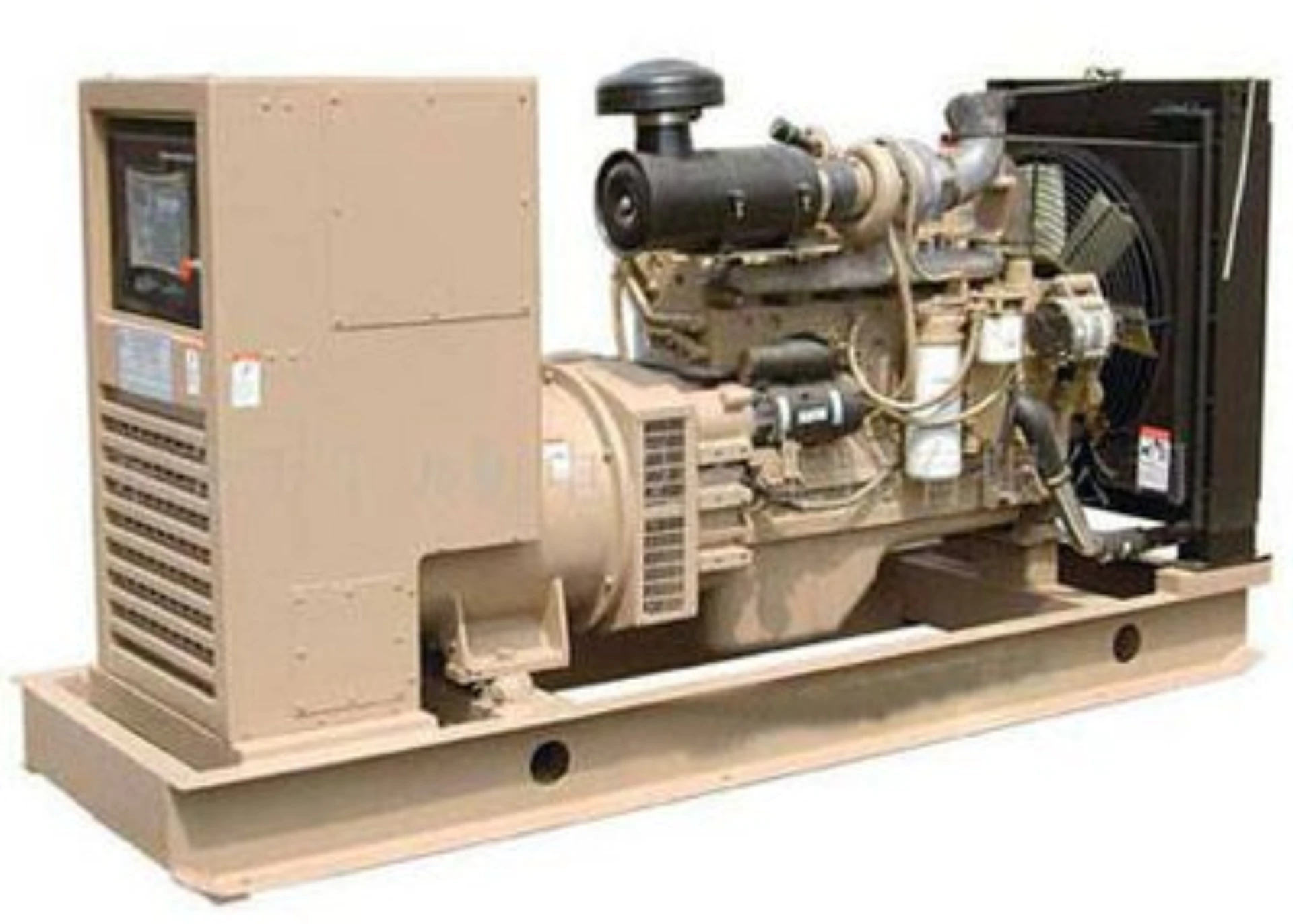
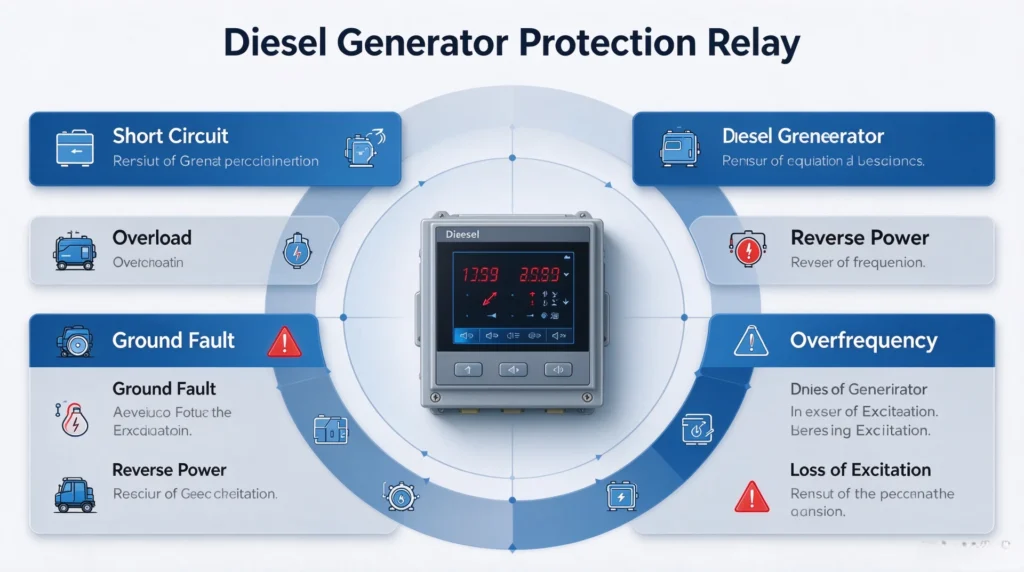
Diesel Generator Protection Relay for Standby and Industrial Sets
A diesel generator protection relay measures voltage, current, frequency and power direction at the generator terminals and trips the breaker before a fault turns into scrap. Standby generator protection is the harder case, because the set may sit idle for weeks and then start unattended into an unknown load.
Written by Leon Zhang, Protection Application Engineer · Technical review by Li Ming, Electrical Engineer · Last reviewed October 2026
At a Glance: What the Relay Covers
- ANSI 50/51 phase overcurrent with two independent stages and delays
- ANSI 51N earth fault on earthed or impedance-earthed neutral systems
- ANSI 87G generator differential for units above roughly 1 MW
- ANSI 32 reverse power, the trip that catches a failed breaker or a closed tie
- ANSI 27 and 59 undervoltage and overvoltage, optionally with a sustained-voltage limit
- ANSI 81U and 81O underfrequency and overfrequency, usually gated against the governor
- ANSI 40 loss of excitation, and ANSI 46 negative sequence for unbalanced loading
- ANSI 78 pole slipping, reported over IEC 61850 or Modbus to the SCADA master
Why a Generator Breaker Is Not Enough
A generator circuit breaker only sees magnitude. It opens on overcurrent, yet it cannot tell an islanded set feeding its own load from a machine that has slipped into motoring mode, and it cannot see power flowing backwards through a stuck breaker on the bus. Generator protection closes that gap with directional and power measurement, which is where ANSI 32 and 87G earn their place on the panel.
Voltage Level Coverage
The relay family covers the voltage levels below:
| Voltage Level | Typical Applications |
|---|---|
| 400V | Small diesel gensets, commercial backup systems, residential standby |
| 6.6kV | Medium industrial generators, mining operations, oil & gas facilities |
| 11kV | Utility-scale diesel plants, large industrial cogeneration |
| 13.8kV | Heavy industrial power generation, large diesel power stations |
Our Supply Capabilities
| Capability | Description |
|---|---|
| Product Range | Numerical protection relays from a basic overcurrent unit up to a full differential scheme |
| Voltage Support | 400V, 6.6kV, 11kV, 13.8kV and custom ratings |
| Communication | IEC 61850, Modbus, DNP3 for SCADA integration |
| Engineering Support | Protection scheme design, relay setting calculation, and commissioning assistance |
| Application Coverage | Emergency standby, industrial gensets, marine, and utility power plants |
Why Choose Our Diesel Generator Protection Solution?
- Proven Reliability – Designed for harsh environments and continuous operation
- Flexible Configuration – Tailored to your specific generator size and application
- Fast Fault Clearing – High-speed fault detection and trip response
- SCADA Ready – Direct integration with modern control systems over IEC 61850 or Modbus
- Global Support – Technical assistance from selection through commissioning
Where These Units Get Installed
| Application | Protection Requirement | Key Protection Functions |
|---|---|---|
| Emergency Standby Generator | Overcurrent, reverse power, voltage, frequency protection | 50/51, 32, 27/59, 81 |
| Industrial Diesel Genset | Overcurrent, unbalance, thermal protection | 50/51, 46, 49 |
| Marine Generator | Reverse power, rotor earth fault, loss of excitation | 32, 64R, 40 |
| Parallel Operation Generator | Differential, reverse power, synchronism check | 87G, 32, 25 |
Application Details
Emergency Standby Generator
Overview: Standby generators provide backup power during grid outages in commercial buildings, hospitals, data centers, and telecommunications facilities. They are typically low-voltage units (400V) that start automatically when the main supply fails.
Key Protection Focus:
- 50/51 Overcurrent – Protects against overloads and short circuits during emergency operation
- 32 Reverse Power – Prevents motoring when the grid returns and the generator fails to disconnect properly
- 27/59 Voltage Protection – Monitors undervoltage and overvoltage conditions to ensure stable power quality
- 81 Frequency Protection – Detects frequency deviations that could damage sensitive loads
Industrial Diesel Genset
Overview: Industrial gensets provide prime or backup power for manufacturing plants, mining operations, oil and gas facilities, and construction sites. These units operate in harsh conditions with frequent load variations.
Key Protection Focus:
- 50/51 Overcurrent – Primary protection for fault clearing and overload conditions
- 46 Negative Sequence Protection – Detects unbalanced loads caused by uneven phase currents, which can cause rotor overheating
- 49 Thermal Protection – Monitors winding and core temperatures to prevent insulation degradation and extend equipment life
Marine Generator
Overview: Marine generators supply power for shipboard systems, propulsion, and auxiliary equipment. They operate in challenging environments with high humidity, vibration and saltwater exposure, so the protection has to hold up between maintenance visits.
Key Protection Focus:
- 32 Reverse Power – Critical for marine applications to prevent motoring during engine failure, which can damage propulsion systems
- 64R Rotor Earth Fault – Monitors rotor insulation integrity, essential for reliable operation in marine environments
- 40 Loss of Excitation – Detects excitation failure that can cause voltage collapse and loss of critical shipboard systems
Parallel Operation Generator
Overview: In parallel operation, multiple diesel generators are synchronized to share loads, improving efficiency and reliability in large industrial facilities and power plants. Parallel operation requires precise protection to ensure stable load sharing and system security.
Key Protection Focus:
- 87G Generator Differential – Provides high-speed primary protection for stator winding faults; essential when multiple generators share a common bus
- 32 Reverse Power – Prevents a generator from motoring when it fails to share load properly; critical for maintaining stable parallel operation
- 25 Synchronism Check – Ensures voltage, frequency, and phase angle match before breaker closing, preventing mechanical stress and system disturbances during parallel connection
Protection Functions for Diesel Generators
The diesel genset protection functions that decide the trip behaviour are 50/51 on the phases, 51N for earth, 87G on the winding and 32 on the power direction. Everything else complements them: 27/59 hold the voltage inside the insulation limits of the machine, 81U and 81O hold the frequency, and 40 or 46 cover the rotor and the unbalance.
| ANSI Code | Protection Function | Purpose for Diesel Generators |
|---|---|---|
| 50/51 | Overcurrent Protection | Fault backup and overload protection |
| 87G | Generator Differential | Internal stator fault protection |
| 32 | Reverse Power | Prevents motoring when engine fails |
| 40 | Loss of Excitation | Excitation system failure detection |
| 46 | Negative Sequence | Unbalanced load protection |
| 27/59 | Voltage Protection | Over/under voltage protection |
| 81 | Frequency Protection | Over/under frequency protection |
| 24 | Overexcitation | V/Hz protection against core saturation |
Why Standby and Prime Sets Need Dedicated Protection
Standby generator protection carries a different burden from prime-duty protection. The set has to start on demand, reach rated voltage within seconds, carry the load, and then shut down cleanly if it cannot. None of that is visible to an overcurrent element alone.
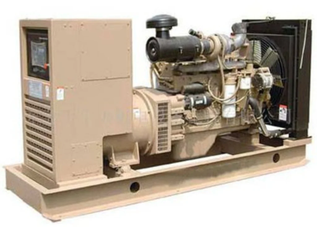
Diesel generators are critical prime and standby power sources for industrial plants, construction sites, mining facilities, marine vessels, and off-grid microgrids.
However, unprotected generator units face severe electrical and mechanical failures that lead to costly downtime, equipment burnout, and grid safety hazards. A high-performance generator protection relay is the core device to guarantee safe, stable, and compliant operation of diesel generator sets.
Risks of Missing or Inadequate Generator Protection
Without standard relay protection, diesel generators are exposed to the following common failures:
- Stator winding burnout and short-circuit damage
- Diesel engine overload and overheating failure
- Reverse power motoring accidents
- Abnormal synchronization and grid connection faults
- Voltage and frequency disturbance to utility public grids
Real Engineering Case Study
A 2MW standby diesel generator at a commercial data center suffered permanent stator winding damage due to missing reverse power protection (ANSI 32).
The generator ran in motoring mode for 8 minutes after prime mover failure, resulting in a total repair cost of over $18,000. By comparison, a multi-function numeric relay costs less than 5% of that maintenance spend.
Core Benefits of Modern Digital Generator Protection Relays
- Greatly improve generator operating reliability
- Minimize unplanned downtime and production loss
- Achieve fast and accurate fault isolation
- Support remote real-time monitoring, data logging and fault diagnosis
- Fully comply with international grid interconnection standards
What Is a Diesel Generator Protection Relay?
Basic Working Principle
A diesel generator protection relay is a numerical intelligent device that collects real-time electrical parameters from CT and PT signals. It continuously monitors voltage, current, frequency, active/reactive power, and insulation status.
Once abnormal operating conditions exceed the preset threshold, the relay will issue alarm or trip commands to disconnect the generator from the load or grid, avoiding secondary damage to engine and generator components.
Complete Protection System Architecture
A standard diesel generator protection system consists of the following core components:
- Generator Current Transformers (CTs)
- Generator Voltage Transformers (VTs / PTs)
- Numerical Generator Protection Relay
- Generator Main Circuit Breaker
- Engine Governor Control System
- Automatic Voltage Regulator (AVR)
- SCADA Remote Monitoring System
ANSI Standard Protection Logic
Global power industries adopt ANSI device number standards to define generator protection functions.
Each protection code corresponds to a specific fault condition, enabling unified engineering design, commissioning, and maintenance across EPC projects worldwide.
Main ANSI Protection Functions for Diesel Generators (Full Parameter Guide)
Overcurrent Protection (ANSI 50/51)
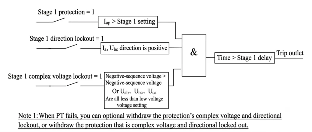
Function Purpose: Detect three-phase short-circuit faults and long-term thermal overload of stator windings, serving as primary and backup current protection.
Applicable Units: All LV (400V/690V) and MV (3.3kV/6.6kV/11kV) diesel generators
Working Stages:
- ANSI 50: Instantaneous overcurrent (fast trip for severe short faults)
- ANSI 51: Time-delay inverse overcurrent (backup overload protection)
Common Field Problem: Nuisance tripping during large motor starting due to high inrush current
Solution: Optimize time-current curve coordination and set reasonable delay time
Earth Fault Protection
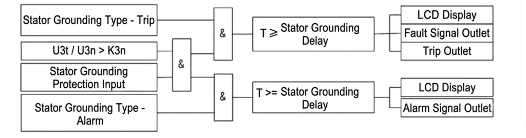
Function Purpose: Detect single-phase ground faults and stator insulation degradation
Main Detection Methods:
- Residual current zero-sequence detection
- Neutral point CT sampling method
Typical Issue: Intermittent earth fault alarms caused by loose wiring or unbalanced system leakage current
Reverse Power Protection (ANSI 32)
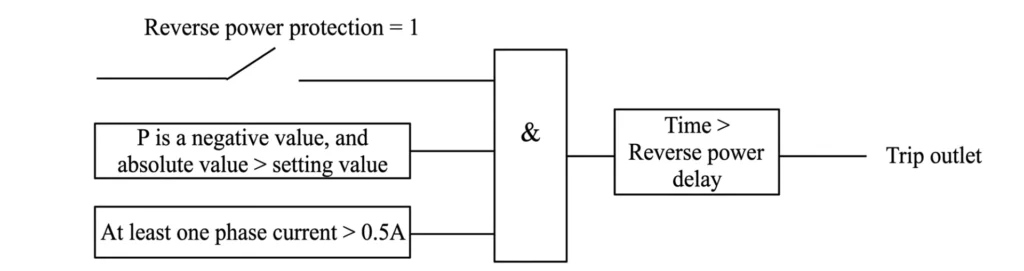
Function Purpose: Prevent generator motoring operation (the generator absorbs active power from the grid)
Core Protection Value: Protect diesel engine from over-speed damage and cylinder burnout after fuel failure or governor trip
Project Case: Fuel supply interruption leads to generator reverse power operation and engine reverse dragging
Industry Standard Setting Range: 2% – 10% of rated active power
Under Voltage Protection (ANSI 27)
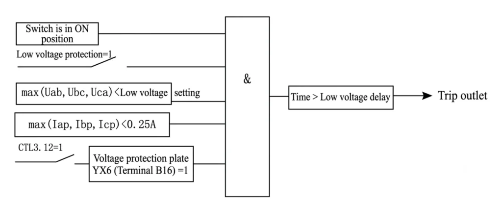
Protected Faults: AVR failure, system short circuit, grid voltage collapse, abnormal load fluctuation
Application: Avoid generator continuous operation under low voltage and over-current heating damage
Over Voltage Protection (ANSI 59)
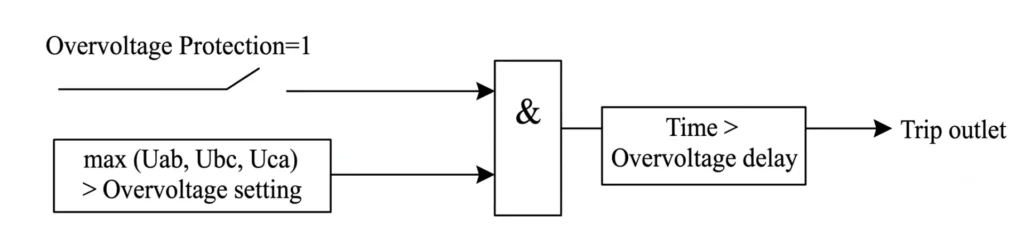
Protected Faults: AVR malfunction, sudden full load rejection, grid voltage surge
Effect: Prevent stator insulation breakdown and electrical component aging
Under frequency relay for generator protection (ANSI 81U)
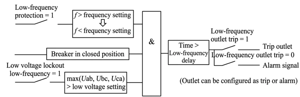
Causes: Governor failure, excessive load exceeding generator rated power, fuel insufficient supply
Function: Cooperate with automatic load shedding to stabilize microgrid frequency and avoid unit stall
Over Frequency Protection (ANSI 81O)
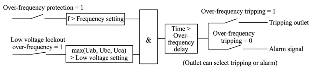
Causes: Sudden load loss, governor hunting and instability, no-load overspeed
Protection Strategy: Multi-stage time-delay trip to avoid false action during transient grid fluctuation
Negative Sequence Protection (ANSI 46)
Core Value: Unbalanced three-phase loads produce negative sequence current, which causes severe rotor surface overheating and aging
Typical Application Scenarios: Industrial unbalanced loads, mining mobile generators, marine power units, single-phase heavy-load systems
Differential Protection (ANSI 87G)
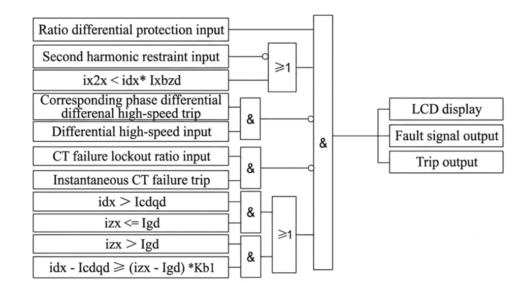
Function: High-sensitivity main protection for stator internal short-circuit faults
Mandatory Configuration Condition:
- Diesel generators above 1MW capacity
- All grid-connected generator units
Advantages: Fast fault clearing, high accuracy, no dead zone for internal faults
Loss of Excitation Protection (ANSI 40)
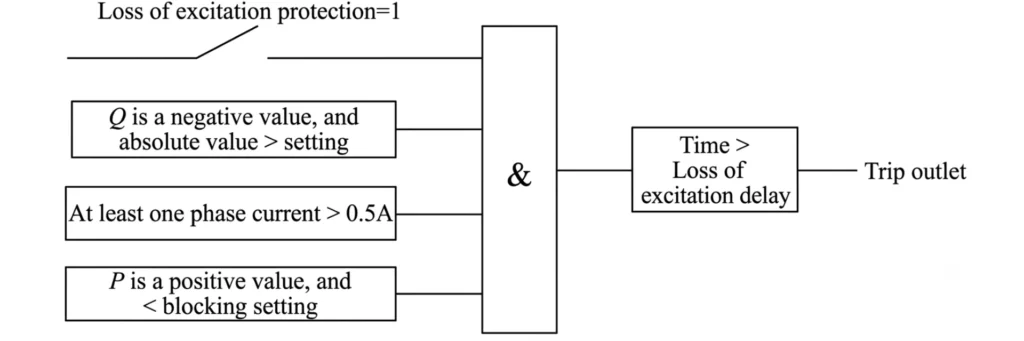
Applicable Units: Brushless synchronous diesel generators
Risks Without Protection: Rotor overheating, reactive power absorption, system voltage collapse, generator out-of-step
Overload Thermal Protection (ANSI 49)
Built-in thermal accumulation model to protect against long-term continuous overload and generator ventilation system failure, preventing insulation thermal aging.
Generator pole slipping protection relay (ANSI 78)
Required for: Large grid-connected diesel power plants and island microgrid systems
Function:Identify system power swing and generator out-of-step faults to prevent grid oscillation collapse with reliable generator out of step protection relays.
Matching Protection Functions by Generator Capacity (Standard Table)
Protection configurations vary according to different diesel generator power ratings. The table below lists industry-standard mandatory protection schemes for engineering project selection, specially designed for this relay family.
| Generator Size | Mandatory ANSI Protection Functions | Application Features |
|---|---|---|
| Small <500kW | 50/51, 50N/51N, 27, 59, 81U/O, 32 | Standby power, simple load, independent operation |
| Medium 500kW–5MW | All small functions + 46 (Negative Sequence), 49 (Thermal Overload), 40 (Loss of Excitation) | Industrial prime power, partial grid connection, unbalanced load |
| Large >5MW | All medium functions + 87G (Differential), 64G (Stator Earth Fault), 78 (Out-of-Step), Advanced Event Recording | Grid-connected power station, microgrid main unit, high reliability requirement |
Diesel Generator Protection Relay Selection Guide
Proper relay selection directly determines power system safety and project compliance. Engineers and buyers must evaluate the following key criteria when specifying Diesel Generator Protection Relays, because an industrial generator protection relay is judged on the same ANSI function list with tighter checks on voltage rating, loading duty and trip response.
Voltage Level
400V / 690V low-voltage generators; 3.3kV / 6.6kV / 11kV medium-voltage generators
Generator Operating Mode
- Standby power (emergency backup)
- Prime power (continuous main power)
- Grid-connected operation
- Island off-grid operation
Communication Protocol Requirements
Match SCADA and remote monitoring system:
- Modbus RTU (basic local monitoring)
- Modbus TCP (Ethernet network monitoring)
- IEC 61850 (substation intelligent standard)
Diesel Generator Protection Relays: Practical Protection Setting Calculation & Standard Values
Mastering generator protection philosophy and relay settings calculations is what keeps a unit stable through a fault. Accurate parameter calibration for Diesel Generator Protection Relays prevents reverse power, overload and earth faults, avoiding costly generator damage caused by improper protection logic.
Overcurrent Setting Calculation (1500kVA Generator Example)
Step 1: Confirm CT ratio. Read the CT ratio off the generator nameplate and the stator rating.
Step 2: Pickup current setting. The pickup has to clear starting inrush current, so hold a margin of 1.2 to 1.5 times the rated current.
Step 3: Time coordination. Match the upstream and downstream time delays so the nearest breaker clears first.
Standard Frequency Protection Settings
- Underfrequency (81U): 47.5Hz ~ 49Hz (adjustable stage delay)
- Overfrequency (81O): 51Hz ~ 52.5Hz (fast trip for severe over-speed)
Reverse Power Standard Setting
Industry unified practice: 2%–5% Pn for large grid-connected units; 5%–10% Pn for small standby diesel units
Common Protection Faults, Causes and Professional Solutions
| Fault Phenomenon | Root Causes | Solutions |
|---|---|---|
| Trip during motor starting | High starting inrush current triggers overcurrent protection | Adjust inverse time curve, increase short-time delay, set inrush restraint |
| False earth fault alarms | CT polarity error, wrong wiring, system grounding resistance abnormality | Recheck secondary wiring, calibrate CT/PT polarity, test grounding system |
| Unexpected reverse power action | Fuel system fluctuation, governor instability, grid reverse surge | Optimize governor PID parameters, increase reverse power delay, adjust threshold |
| Frequent under-frequency tripping | Overloaded operation, fuel supply insufficient, governor aging | Reduce invalid load, maintain fuel system, recalibrate governor speed loop |
Relay Testing & Commissioning Standards
FAT (Factory Acceptance Test)
Complete factory functional verification, logic simulation, and communication testing before delivery.
SAT (Site Acceptance Test)
On-site items: CT/PT polarity verification, trip circuit inspection, secondary injection test, interlock logic check.
Recommended Test Tools
- Secondary Injection Test Set
- Universal Relay Test Kit
- Power Quality Analyzer
Industry Compliance Standards
All diesel generator protection systems must comply with international authoritative standards:
- IEEE C37 Series (Relay Protection Standard)
- IEC 60255 (Measuring Relays and Protection Equipment)
- IEC 60034 (Rotating Electrical Machines)
- IEEE 1547 (Grid Interconnection Standard)
- NFPA 110 (Emergency and Standby Power Systems)
Standard compliance ensures project acceptance, grid connection approval, and long-term safe operation.
How to Choose a Qualified Relay Manufacturer
Core Evaluation Indicators for Buyers
- Complete ANSI protection function coverage
- Professional global technical support
- Complete engineering documents and setting manuals
- On-site commissioning guidance capability
- Overseas EPC project experience
- Global spare parts supply system
Chinese vs European Protection Relays
Chinese brand relays provide full functions, stable performance, lower cost, shorter delivery time, and flexible customized technical support, which is the most cost-effective solution for global EPC, generator integrators and overseas power projects.
FAQ – Frequently Asked Engineering Questions
1. What protections does a 1MW diesel generator need?
A: 50/51 overcurrent, 50N/51N earth fault, 27/59 voltage protection, 81U/O frequency protection, 32 reverse power, and optional 46 negative sequence protection.
2. Is differential protection necessary for diesel generators?
Differential protection (87G) is mandatory for generators above 1MW and all grid-connected units; small standby generators can omit it according to project budget.
3. What is the standard reverse power setting?
A: 2%–10% of rated active power, adjusted according to unit size and operating mode.
4. How often should protection relays be tested?
A: Annual routine calibration; full secondary injection test after generator overhaul or grid reconstruction.
5. Which protocol is best for SCADA?
A: Modbus TCP for general projects; IEC 61850 for intelligent substation and high-end grid projects.
Conclusion
Diesel generator protection relays are the final safety barrier for power generation equipment. Correct relay selection, accurate parameter setting, standardized commissioning and regular maintenance can effectively extend generator service life, reduce failure rates, and ensure compliant and stable operation of standby and prime power systems.
Relay configuration must match generator capacity, voltage level, and grid-connected/island operating conditions. Reasonable fault solution experience can help engineers avoid common nuisance tripping and protection failure risks in actual projects.
Free Engineering Support & Custom Solution
If you need help with relay selection, setting calculation or protection scheme design, please send the generator parameters:
- Generator rated capacity
- Voltage level
- CT/PT ratio
- Operating mode (standby / prime / grid-connected / island)
Our professional power engineering team will provide a full set of protection scheme + standard relay setting values for your project.
Related reading
Three places to read next follow: the generator protection relay hub that carries the full ANSI function list, the emergency generator panel where the relay, breaker and CTs are built up on one board, and the generator backup protection relay usually specified for standby service.
Technical References and Data Sources
Each standard below is listed for the clause or scope named, not as general background.
| Source | What it covers | Type | Edition |
|---|---|---|---|
| ANSI/IEEE C37.102 | Guide for AC generator protection, including differential, reverse power, loss of excitation and setting philosophy | Guide | 2023 |
| ANSI/IEEE C37.2 | Device function numbers and suffixes used on generator schemes | Standard | 2022 |
| IEEE 1547 | Interconnection and interoperability of distributed energy resources, including standby units that stay on the network | Standard | 2018 |
| IEC 60255-1 | Common requirements for measuring relays and protection equipment | Standard | 2022 |



About Author

Hello, I'm Leno Zhang. I have 15 years of experience in the power relay protection industry with extensive pre-sales and after-sales project experience. Our company specializes in various complete sets of relay protection and automation equipment. I can assist customers in solving all practical on-site project challenges and provide optimal integrated solutions.
Tell Us Your Requirement
High Quality
Stable performance, reliable design, ensuring safe operation for power system protection and grid stability.
Fast Delivery
Timely delivery to support your urgent orders and project schedules efficiently and professionally at any time.
Best Warranty
Professional Warranty: Reliable after-sales support for stable relay protection and long-term customer satisfaction.