
-
Leon Zhang Sales Manager
-
Email: sale@relayprotect.com
-
Phone/WhatsApp: +86 13655813266
Relay Troubleshooting Guide: 8 Common Protection Relay Problems and How to Fix Them
What are the most common protection relay problems and where do they originate?
Protection relay troubleshooting starts by separating the device from everything around it: eight recurring problems account for most site call-outs, and only two of them are inside the relay. The rest sit in the settings, the CT and VT wiring, the trip circuit or the communication link. That ordering matters, because a relay that measures correctly and trips on a bad setting looks like a failed relay until you read the event record. Common problems fall into four groups: electrical, configuration, environmental and ageing; only ageing is unavoidable. Nuisance tripping shows up as a breaker opening with no fault, unwanted pickup during motor start or random shutdown, generally from a low pickup setting, CT saturation, harmonics or transformer inrush. Failure to trip comes from wrong settings, reversed CT polarity, an open CT secondary or bad logic. Device numbers follow ANSI/IEEE C37.2-2022; relay requirements IEC 60255-1:2022. Setting review and quotation within 12 hours, MOQ 1, 7-15 working days.
Protection relay troubleshooting starts by separating the device from everything around it: eight recurring problems account for most site call-outs, and only two of them are inside the relay. The rest sit in the settings, the CT and VT wiring, the trip circuit or the communication link.
That ordering matters. A relay that measures correctly and trips on a bad setting looks exactly like a failed relay until you read the event record. The record, not the front panel, is what tells you which of the eight you have.
Read the record first. Change nothing yet.
At a Glance
- Two of eight are device faults: HMI or power supply failure, and internal self-test alarms. The other six start in the settings, the wiring, the CT circuit or the communication link.
- Nuisance tripping (ANSI 50/51, 87): pickup set below load, CT saturation, inrush current, harmonics.
- Failure to trip (ANSI 50/51, 87): reversed CT polarity, open CT secondary circuit, wrong logic configuration.
- Overcurrent not operating (ANSI 50/51): wrong pickup, wrong time curve, CT ratio mismatch.
- Earth fault not operating (ANSI 51N/51G, 64): residual wiring, sensitive setting, zero-sequence CT installation.
- Communication loss (no device number): address, baud rate, IP, cable and port.
- Wrong measurements (no device number): CT/PT ratio, primary or secondary wiring, phase sequence.
- First check, every time: the event record and the disturbance waveform, before any setting is touched.
Device numbers on this page follow ANSI/IEEE C37.2-2022. Requirements for the relay itself, including performance and testing, are in IEC 60255-1:2022. Function numbers shift between revisions, so confirm the issue in force before you write a test sheet against them.
Why Protection Relay Problems Occur
Common protection relay problems fall into four groups: electrical, configuration, environmental and ageing. Only the last one is unavoidable, and every one of them starts outside the relay more often than inside it. That split is what protection relay troubleshooting rests on, so the group you are in decides where the work starts.
| Electrical Issues | Configuration Errors | Environmental Factors | Hardware Aging |
|---|---|---|---|
| Incorrect CT/PT wiring | Incorrect parameter settings | High ambient temperature | Electronic component aging |
| Abnormal current input | Incorrect setting value calculation | High humidity | Power supply module failure |
| Loss of voltage | Wrong communication configuration | Electromagnetic interference (EMI) | Poor contact |
Selecting a relay for a live project?
Send the system voltage, CT ratio and tripping scheme. Our engineers confirm the model and reply within 12 hours.
Common Protection Relay Problems Summary
Problem #1 – Nuisance Tripping (Unexpected Relay Trips)
Problem 1: Symptoms
Relay nuisance tripping (false relay operation / relay trips without fault) manifests as breaker tripping with no actual fault, unwanted relay pickup during motor startup and unplanned random equipment shutdown.
Problem 1: Root Causes
This issue generally arises from four key factors: overly low pickup setting, CT saturation, harmonic interference and transformer inrush current.
Problem 1: Solutions
To resolve it, technicians shall verify protection parameters, properly set operating time delay, check CT transformation ratio and analyze disturbance event records.
Problem #2 – Relay Fails to Trip During Fault Conditions
Problem 2: Symptoms
Relay failure to trip occurs when protection remains inactive during real faults, eventually resulting in equipment damage.
Problem 2: Root Causes
The fault is mainly caused by incorrect protection settings, reversed CT polarity, open CT secondary circuit and wrong logic configuration.
Problem 2: Solutions
Carry out secondary injection testing, cross-check with wiring diagrams, and test trip circuit continuity.
Problem #3 – Overcurrent Relay Not Working Properly
Such failures are usually caused by wrong pickup current, incorrect time curve and CT ratio mismatch, and troubleshooters can resolve these issues by recalculating settings, verifying load current and performing relay testing.
Device quality is another contributing factor.
Some relays sold on price alone do not meet industrial requirements for workmanship or specification. Sampling accuracy is where the gap usually shows: the readings drift away from the reference within weeks, and no setting change will bring them back.
Some units develop abnormal sampling within less than one month of commissioning: readings from the relay deviate drastically from actual CT values or show abnormally low measurements, resulting in either nuisance tripping or failure to trip of circuit breakers.
Problem #4 – Earth Fault Protection Not Operating
Problem 4: Symptoms
The relay fails to operate when an actual ground fault happens.
Problem 4: Root Causes
- Wrong residual current wiring
- Neutral grounding system faults
- Improper sensitive setting for earth fault protection
Problem 4: Solutions
- Recheck and adjust earth fault protection settings
- Inspect the whole grounding system
- Check zero-sequence CT installation
Such failures occur frequently. It is recommended to analyze the problem combined with the fault indication from the small-current earth fault feeder selection device.
Problem #5 – Communication Failure Between Relay and SCADA
Problem 5: Symptoms
SCADA data cannot be read normally and remote monitoring drops out, which are typical signs of relay communication faults.
Problem 5: Root Causes
- Incorrect communication address and station number settings
- Mismatched baud rate, data bit, stop bit and parity check parameters
- Wrong IP address, subnet mask and gateway configuration
- Poor network cable contact, damaged line or switch port failure
- Communication module abnormality or program operation exception
Problem 5: Solutions
- Verify and correct the device Modbus address and communication station number to ensure consistency with the SCADA host settings.
- Unify communication parameters including baud rate, parity check and frame format between the protection device and the background system.
- Recheck IP address, subnet mask and gateway configuration to eliminate network parameter conflicts.
- Inspect and replace network cables, test network channel connectivity, and troubleshoot switch and network port faults.
- Restart the protection device, upgrade or restore the firmware, and replace faulty communication modules if necessary.
Apart from the above common faults, electromagnetic interference is another critical root cause requiring close attention.
Improper routing of field communication cables is highly susceptible to strong power interference, which triggers abnormal communication and may even burn out the device’s communication ports. Such faults have been encountered during on-site commissioning: intermittent communication dropout and garbled communication messages.
Problem #6 – Incorrect Relay Measurements
Problem 6: Symptoms
Abnormal measured values: incorrect current reading, wrong voltage indication and inaccurate power calculation.
Problem 6: Root Causes
- Mismatched CT / PT transformation ratio
- Incorrect primary or secondary wiring
- Out-of-calibration device parameters
Problem 6: Solutions
- Perform equipment calibration
- Confirm CT and PT rated ratios
- Inspect wiring and phase sequence
The elimination method is the practical way through these faults: check potential fault points one by one. After confirming the protection device itself works properly, proceed to inspect external faults. For projects that have been in normal operation for a period of time, most such measurement failures stem from quality defects of the relay protection equipment.
Problem #7 – Frequent Relay Alarm Messages
Problem 7: Symptoms
Common customer inquiries focus on protection relay alarms and self-diagnostic alerts, including device fault alarm, CT circuit supervision alarm, VT fuse failure alarm and communication failure alarm.
Problem 7: Root Causes
Internal hardware abnormality, secondary circuit faults and communication parameter errors.
Problem 7: Solutions
- Inspect related external secondary circuits
- Check historical event logs
- Review built-in self-diagnostic records
To sum up, relay alarms fall into two categories. The first is self-test abnormality alarms caused by internal device faults, which shall be reported to the manufacturer for repair. The second is fault-related alarms; troubles shall be located step by step by referring to the product manual, alarm logs and on-site construction drawings, and the elimination method is preferred for troubleshooting.
Problem #8 – Relay Display or HMI Not Responding
Problem 8: Symptoms
Common hardware faults: blank screen, frozen screen interface and unresponsive buttons.
Problem 8: Root Causes
- Unstable or faulty power supply
- Corrupted or abnormal firmware
- Internal hardware breakdown
Problem 8: Solutions
- Reach out to professional technical support
- Restart the device by power cycling
- Carry out official firmware upgrading
A simple method is available for fault judgment: If background SCADA data is normal, the fault lies with the display screen, and replacement of the display and associated accessories can resolve the issue. In case of a blank screen accompanied by missing background monitoring data, the CPU module or power supply module is likely damaged, and manufacturer on-site service is the next step.
Protection Relay Problems by ANSI Function
The eight problems map onto a short list of protection functions, from overcurrent to earth fault protection. This is where relay faults and fixes meet: the fix depends on which function misbehaved, not on the symptom you noticed first.
| Problem | ANSI function | What has failed | First check |
|---|---|---|---|
| 1. Nuisance tripping | 50/51, 87 | Pickup below load, CT saturation, inrush, harmonics | Event record and disturbance waveform |
| 2. Fails to trip | 50/51, 87 | Reversed CT polarity, open CT secondary, wrong logic | Secondary injection and trip circuit continuity |
| 3. Overcurrent not operating | 50/51 | Wrong pickup, wrong time curve, CT ratio mismatch | Recalculate against measured load current |
| 4. Earth fault not operating | 51N/51G, 64 | Residual wiring, sensitive setting, zero-sequence CT | Residual current wiring and CT orientation |
| 5. Communication failure | no device number | Address, baud rate, IP, cable or port | Link status and parameter match with the host |
| 6. Incorrect measurements | no device number | CT/PT ratio, primary or secondary wiring, phase sequence | Compare against a reference meter |
| 7. Frequent alarms | no device number (self-supervision) | Internal hardware, secondary circuit, communication parameters | Alarm log and built-in self-diagnostic record |
| 8. HMI not responding | no device number | Auxiliary supply, firmware, CPU or display module | Whether SCADA data is still updating |
Protection Relay Troubleshooting: A Six-Step Sequence
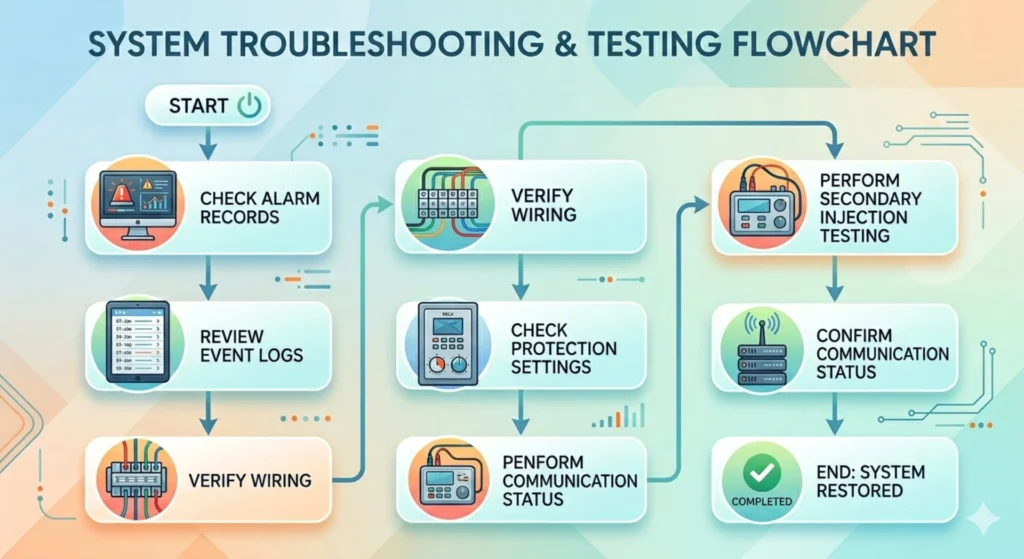
Relay failure diagnosis is a sequence, not a search. Work from the record outward: confirm what the relay saw, confirm what actually flowed on the primary circuit, then decide whether the device, the setting or the input is wrong.
- Pull the event record and the disturbance record before touching anything.
- Compare the recorded current and voltage against what the primary circuit was doing at that moment.
- Check the setting file against the coordination study: pickup, curve and delay.
- Verify CT ratio, polarity and burden against what the relay is configured for.
- Test trip circuit continuity from the relay output through to the breaker coil.
- Check the auxiliary supply and the communication link last. Both are quick to test and rarely the cause.
The order is cheapest first. Steps one to four cost nothing but time, and that is what keeps protection relay troubleshooting cheap: only after they come back clean does it make sense to suspect the device.
Preventive Maintenance Tips for Protection Relays
Prevention is the cheap end of protection relay troubleshooting, and it is mostly schedule. Regular relay maintenance covers multiple key items including routine testing and annual relay testing for full functional verification, timely firmware updates to keep software current, environmental control over working temperature and humidity, as well as regular event log analysis to realize early fault detection.
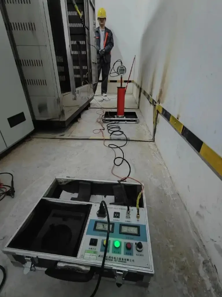
It should be noted that all abnormal phenomena occurring during regular equipment operation shall be sorted out and filed in advance. During power-outage maintenance, targeted tests shall be performed on relevant equipment to completely eliminate faults and hidden dangers.
When Should You Replace a Protection Relay?
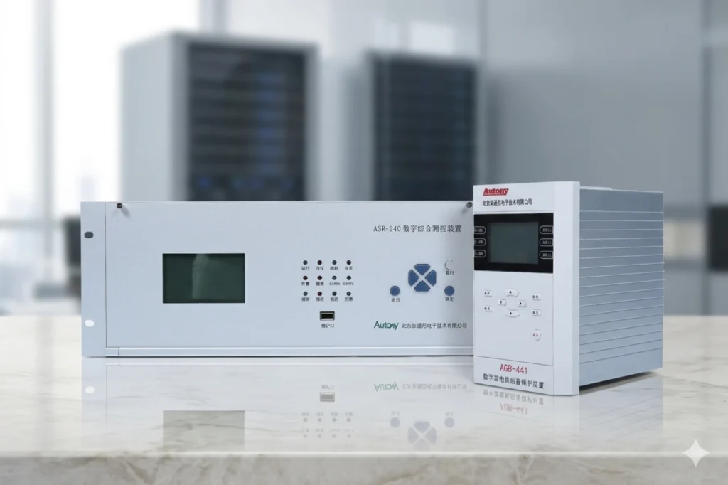
Frequent equipment failures, unsupported firmware, obsolete communication protocols and excessive maintenance costs are typical drawbacks of outdated relay devices, while modern digital protection relays come with outstanding advantages including IEC 61850, Modbus TCP, built-in self-diagnostics and advanced fault recording functions.
Higher specifications do not always mean better suitability.
Product compatibility with actual project requirements should be prioritized. Brand-new products with the latest specification lack field hours, and that is when unexpected faults show up. Mature and field-proven products that have stood market tests shall be preferred.
Frequently Asked Questions (FAQ)
Why does my relay trip without a fault?
Nuisance tripping is mainly caused by a pickup set below normal load, CT saturation under fault current, transformer inrush and harmonic interference. Start with the event record: it shows whether the relay measured a real current or a distorted one. Then check the pickup against the coordination study and the CT ratio and burden against what the relay is configured for. Changing the setting without reading the record usually moves the problem elsewhere.
Why is my overcurrent relay not operating?
It usually results from a CT ratio that does not match the relay configuration, a pickup set above the fault current, or a time-current curve that is too slow for the coordination interval. Recalculate the settings from the study, then confirm them with a secondary injection test at the pickup and at one point on the curve. If the relay still does not operate, the cause is downstream: the trip circuit, the breaker coil or the DC supply.
How often should protection relays be tested?
Routine inspection every year and full secondary injection testing every 2 to 3 years is the common pattern, but the interval should follow the local power industry standard and the duty the relay sees. A unit that has tripped twice without explanation should be tested now rather than at the next scheduled date. Keep the test record: it is the baseline the next engineer compares against.
Can incorrect CT wiring affect relay performance?
Yes. Wrong polarity, an open-circuited CT secondary or reversed wiring leads to measurement deviation, refusal to operate on a real fault, or tripping when nothing is wrong. Polarity errors are the ones that survive commissioning: they only show up on differential and directional elements, and only under load or fault. An open CT secondary is also a safety hazard, because it drives the secondary voltage to dangerous levels.
What causes relay communication failures?
Wrong Modbus address or station number, mismatched baud rate, parity or frame format, a wrong IP address or gateway, and poor network cabling are the common reasons. Electromagnetic interference on communication cables routed alongside power conductors causes intermittent dropouts that look like parameter errors. Check link status and physical cabling before you start changing protocol settings.
How do I tell whether the relay or the CT is at fault?
Inject a known current into the relay secondary with the CT disconnected. If the relay measures it correctly, the relay and its setting are sound and the problem is in the CT, the burden or the wiring. If the reading is still wrong, the fault is in the relay. This one test splits the measurement chain in half, which is why it comes before any setting change.
Should a faulty protection relay be repaired or replaced?
Replace when the failure is in the power supply, the CPU module or the display, when the firmware is no longer supported, or when the communication protocol the station uses has been dropped. Repair only makes sense for a single failed module on a current product with support. Age, not the fault itself, is usually what decides it: once spares and firmware support are gone, every future call-out costs more than the replacement.
Need Help Solving Relay Protection Problems?
Send the event record, the CT ratio and accuracy class, and the setting file. That is usually enough to say whether protection relay troubleshooting should start at the settings, the measurement chain or the device.
For a quotation on a replacement or a retrofit, include the single-line diagram, the I/O list and the protocol you need. Those three set the scope faster than a written enquiry.
Conclusion
Protection relay troubleshooting ends in one of three places: a setting that no longer matches the study, an input that no longer matches the primary circuit, or a device that has reached the end of its life. The eight problems above cover all three, and six of the eight cost nothing to check.
Before you order a replacement, pull the event record and run the six-step sequence. Most call-outs that look like a failed relay turn out to be a setting, a CT circuit or a cable.
Related Reading
- Protection relay nuisance tripping – the eight field causes behind a trip with no fault, and the check for each.
- Protective relay maintenance – test intervals, scope and what to record each visit.
- Protection relay testing and commissioning – secondary injection, primary injection and the test report.
- Relay protection training and testing – what a test campaign covers on site.
- Setting an overcurrent relay correctly – where pickup, curve and delay values come from.
- Protection relay setting calculation – the study behind the numbers in the setting file.
- Frequency relay protection – ANSI 81 and the under- and over-frequency elements.
- Temperature protection – ANSI 49 and the thermal elements that age with the plant.
- Small-current grounding line selection – the feeder selection device behind earth fault indication.
- Power SCADA monitoring cabinet – where the relay data lands once the link is up.
Relay installed, never trips: check the units first
When a relay is installed, powered, communicating, and still does not trip on a real fault, the wiring gets blamed first and the setting units last. They should be the other way round. A pickup of 100 A on a 600/5 CT equals 12,000 A of primary current, so the element is waiting for a fault the network cannot produce – the relay is not faulty, it is being asked the wrong question. We have seen exactly this on a live setting sheet. Before changing hardware, read the sheet back and ask one question of every row: is this number in secondary amps? If the figure happens to look like a sensible primary current, that is the tell. Country by country: project record.
Technical References
| Standard | What it covers here | Edition |
|---|---|---|
| ANSI/IEEE C37.2 | Device function numbers: 50/51, 87, 51N/51G, 64 | 2022 |
| IEC 60255-1 | Measuring relays and protection equipment: common requirements, performance and testing | 2022 |
| IEC 60255-26 | Electromagnetic compatibility requirements for protection equipment | check current edition |
| IEC 61869-2 | Current transformers: ratio, accuracy class and rated burden | 2012 |
| IEC 61869-3 | Voltage transformers: ratio and accuracy | 2011 |
| IEC 61000-4-30 | Power quality measurement methods; class A and class S are defined in Clause 4 | 2025 |
| IEC 61850-8-1 | Station bus communication mapping for protection IEDs | 2011+AMD1:2020 |
Editions change. Confirm the current version against the publisher catalogue before you write a test sheet or a specification against any of them.
Questions on the settings in this guide go to the engineering team, normally answered the same working day.
About Author

Hello, I'm Leon Zhang. I have 15 years of experience in the power relay protection industry with extensive pre-sales and after-sales project experience. Our company specializes in various complete sets of relay protection and automation equipment. I can assist customers in solving all practical on-site project challenges and provide optimal integrated solutions.
Tell Us Your Requirement



High Quality
Stable performance, reliable design, ensuring safe operation for power system protection and grid stability.
Fast Delivery
Timely delivery to support your urgent orders and project schedules efficiently and professionally at any time.
Best Warranty
Professional Warranty: Reliable after-sales support for stable relay protection and long-term customer satisfaction.