

-
Leon Zhang sales consultant
-
Email: zxl635973785@gmail.com
-
Phone/WhatsApp: +86 13655813266
What Are Protective Relays? Definition, Types and How They Work
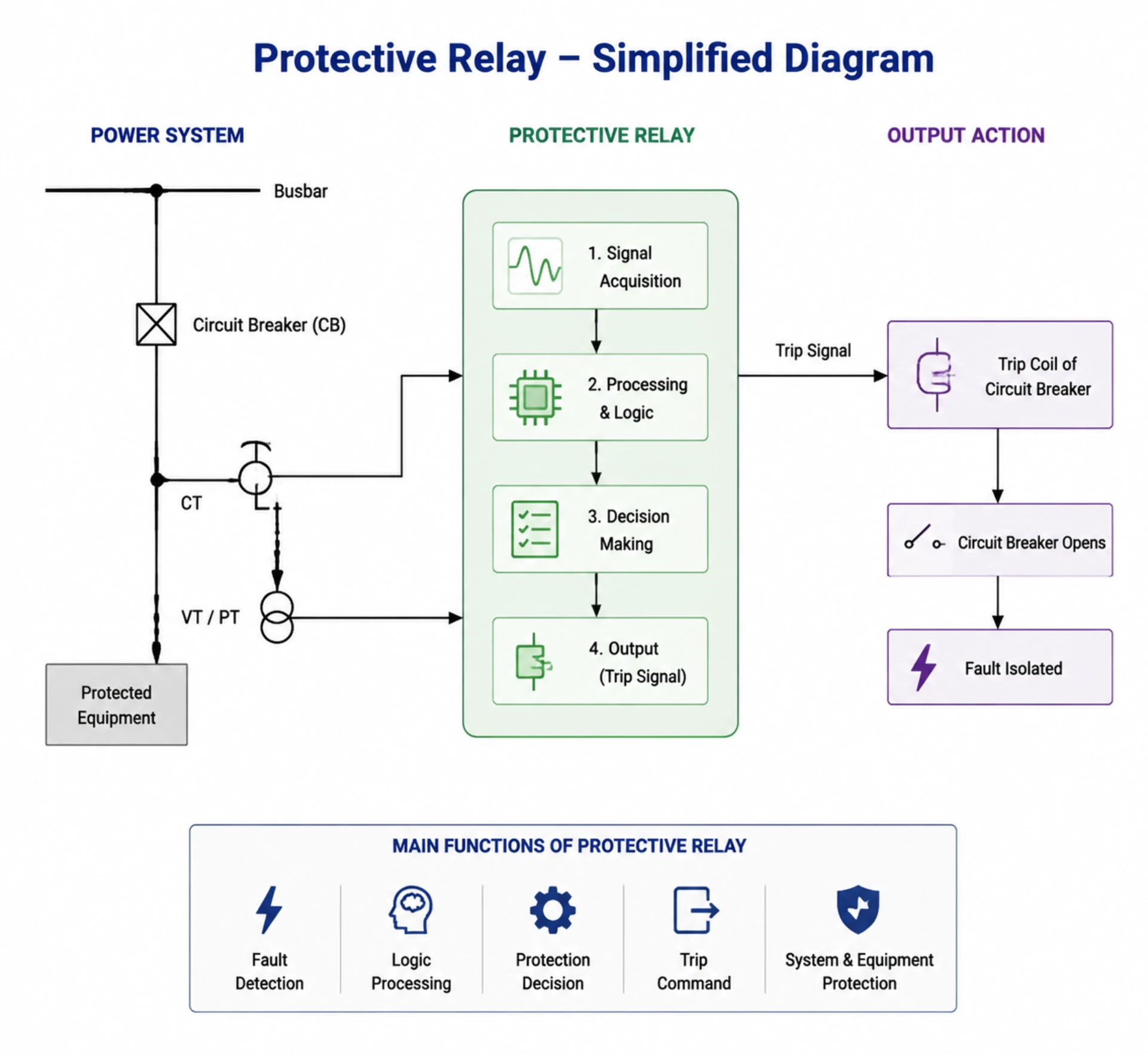
What are protective relays? They are the devices that read current, voltage and frequency on a circuit and tell a breaker to open when those values leave the safe band. A relay never clears a fault on its own. It decides that the fault is real, then hands a trip command to the breaker that does the clearing. This page covers the definition written into IEC standards, the seven families sold, the four-step operating sequence, and what to check before one goes into a specification.
At a glance: a numerical relay reaches a trip decision in 15 to 30 ms on a 50 Hz system, keeps the last hundred or more events in non-volatile memory, and writes a disturbance record in COMTRADE format that can be replayed off site. Accuracy, burden and response are type tested under IEC 60255-1:2022. Immunity to electromagnetic disturbance falls under IEC 60255-26:2023 and product safety under IEC 60255-27:2023. Device numbers come from ANSI/IEEE C37.2-2022.
Eleven device numbers carry most of the protection on an industrial or utility board:
- ANSI 50 and 51, instantaneous and time overcurrent: feeders, cables and motor starters.
- ANSI 50N and 51N, earth fault: residual current on MV networks and generator stators.
- ANSI 87, differential: transformers, generators, busbars and long cable circuits.
- ANSI 21, distance: impedance to the fault on transmission lines.
- ANSI 46, negative sequence: unbalance and lost phase on motors.
- ANSI 49, thermal replica: overload, locked rotor and repeated starting duty.
- ANSI 27 and 59, under and overvoltage: bus transfer, load shedding and islanding.
- ANSI 32 and 40, reverse power and loss of excitation: generators and prime movers.
- ANSI 50BF, breaker failure: backs up a breaker that did not open on command.
- ANSI 79, reclosing: restores a line after a transient fault.
- ANSI 81, frequency: load shedding and generator set protection.
Four standards decide what the hardware has to meet before it can be specified. IEC 60255-1:2022 sets the common requirements for measuring relays and protection equipment, IEC 60255-26:2023 sets electromagnetic immunity and IEC 60255-27:2023 sets product safety for equipment up to 1 000 V AC. Communication with a substation bus follows IEC 61850-8-1:2011+AMD1:2020, with IEC 60870-5-103:1997 still common on serial retrofits. Motor duty is judged against IEC 60034-1:2026 and NEMA MG-1-2021.
Below, the protective relay definition is unpacked first, then the types, then the operating sequence in four steps, then the testing and selection checks that follow. Each section stands on its own if you already know the rest.
Short version: choose on protected object, input quantities and required records.
The protective relay definition written into IEC 60255-1:2022 is deliberately narrow: a measuring relay or protection equipment that detects an electrical fault or an abnormal operating condition and then initiates a trip, an alarm or both. That one sentence covers the electromechanical disc relay still working on 1970s boards and the numerical unit on a smart substation built this year. What separates the two is operating speed, how many functions fit in one case, and whether the device can report what it saw.
Why Are Protective Relays Critical for Power Systems?
Modern power grids, renewable energy stations, and industrial power distribution systems cannot operate safely without qualified protective relays. Their core values cover equipment protection, system reliability, and personnel safety.
Prevent Costly Electrical Equipment Damage
Electrical faults such as short circuits and overcurrent can generate instantaneous high temperature and high current, burning out transformers, generators, motors and switchgear. Protective relays cut off faulty circuits within milliseconds to avoid permanent equipment failure and huge replacement and maintenance costs.
Improve Power System Reliability & Reduce Outage Losses
Relays accurately locate and isolate local faults, preventing fault diffusion from affecting the entire grid. This drastically reduces unplanned outage time, guarantees continuous power supply for industrial production, commercial facilities and residential areas, and lowers economic losses caused by power failures.
Ensure On-Site Personnel Operational Safety
Ground faults, arc faults and abnormal overvoltage easily trigger electric shock and arc explosion accidents. Professional protective relays match multiple safety protection logics to eliminate potential safety hazards and protect construction and operation personnel.
How Do Protective Relays Work? (Complete Working Process)
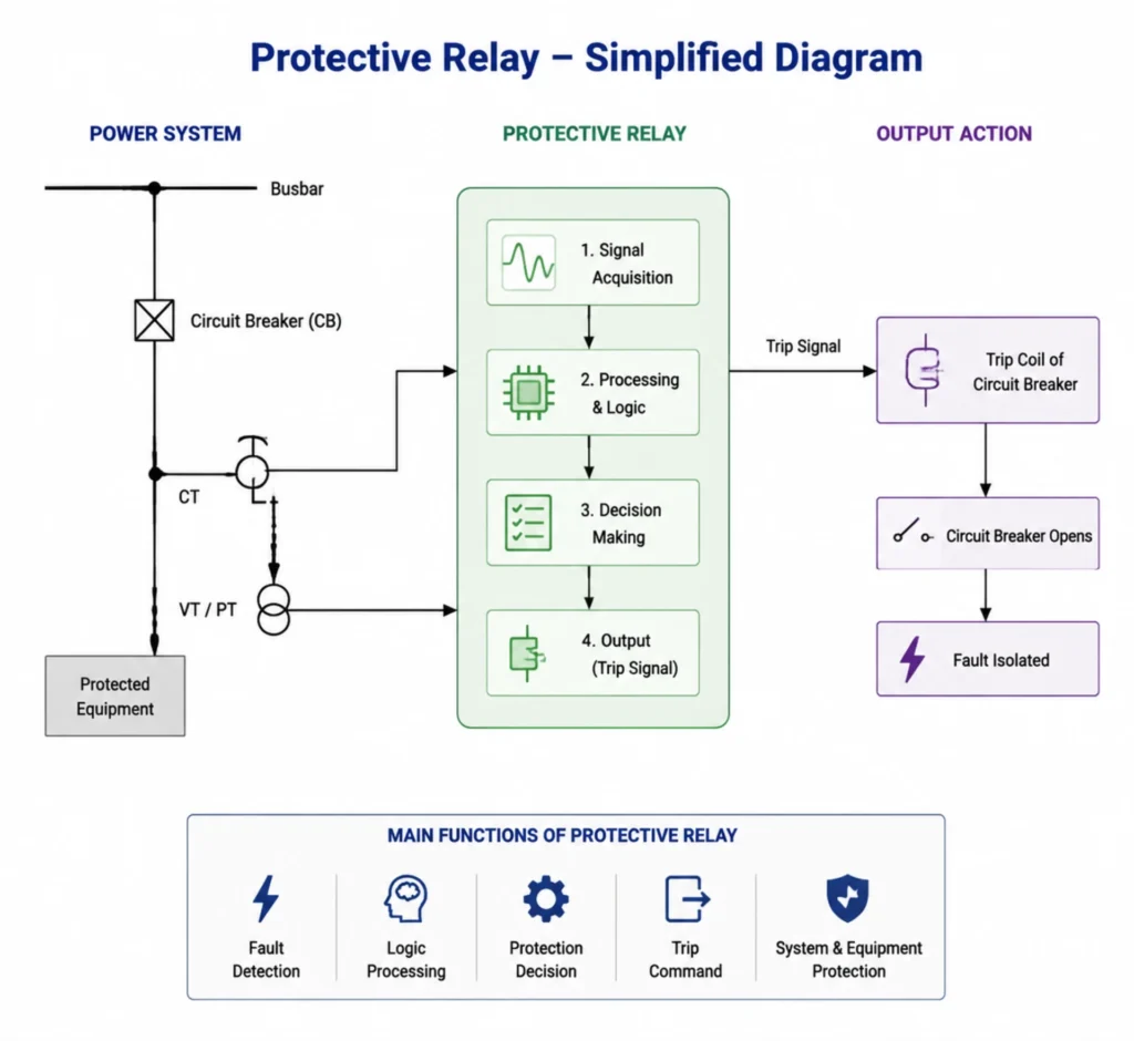
The four steps below set out how protective relays work, from the analogue input to the trip contact. Every static and numerical relay on the market runs the same sequence. Standards bodies describe the same loop as sensing, measurement, comparison and output, which is the shape used in protective relay operating principle guides and in the functional requirements of protective relay functions.
Real-Time Parameter Monitoring
Relays collect real-time operating data of the power system through matched CT and PT, including current, voltage, frequency, phase angle and active/reactive power, to grasp the operating status of electrical equipment in real time.
Abnormal Fault Identification
The built-in program automatically compares real-time monitored data with preset threshold values to identify common faults: overcurrent, short circuit, earth fault, overvoltage, undervoltage and frequency deviation.
Intelligent Protection Decision-Making
According to pre-set pickup values, time delay parameters and protection curves, the relay judges the fault type and severity, and confirms whether to trigger protection actions to avoid misoperation and refusal operation.
Execute Trip & Isolation Commands
Once a valid fault is confirmed, the relay instantly outputs a trip signal to the circuit breaker. The breaker opens the faulty circuit to isolate the fault area, ensuring the normal operation of the rest of the power system.
Fault Response Flow
Fault Occurs → Relay Captures Abnormal Data → Compare with Setting Parameters → Output Trip Command → Circuit Breaker Opens → Fault Isolated
That is the whole loop.
Protective Relay Types by ANSI Device Number
What are protective relays sold as? Seven protective relay types cover nearly every project. Each is named by the quantity it compares and carries an ANSI device number. Select by the object being protected, then check which input quantities the device needs, because that is where mismatches happen.
| Type | ANSI | What it compares | Typical object |
|---|---|---|---|
| Overcurrent and earth fault | 50, 51, 50N, 51N | Measured current against a pickup and a time curve | Feeders, cables, motor starters |
| Differential | 87, 87T, 87G, 87M | Current entering against current leaving | Transformers, generators, busbars |
| Distance | 21 | Line impedance to the fault location | Transmission and sub-transmission lines |
| Motor protection | 49, 46, 37, 48 | Thermal replica, negative sequence, starting time | HV and MV motors, pumps, compressors |
| Generator and transformer | 32, 40, 87G, 87T | Reverse power, field loss, winding differential | Power plant units and station transformers |
| Voltage and frequency | 27, 59, 81 | Bus voltage and system frequency against limits | Bus transfer, load shedding, islanding |
| Breaker failure | 50BF | Trip issued against current that never stopped | HV and MV boards with backup tripping |
Protection Relay 50 51
Divided into instantaneous overcurrent (ANSI 50) and time-delay overcurrent (ANSI 51). It is the most basic and widely used protection type, mainly used for distribution network feeders, low and medium voltage motors, and terminal power distribution circuits to cope with overload and short-circuit faults.
Differential Protection Relay (ANSI 87)
Judge faults by detecting the current difference between the two ends of equipment. It features high sensitivity and strong anti-interference ability, and is dedicated to key core equipment: power transformers, generators and busbars, serving as primary protection for main station equipment.
Distance Protection Relay (ANSI 21)
Distance protection relays locate fault points by measuring line impedance. They serve as the standard protection for high-voltage transmission lines, which can rapidly calculate fault distances and implement sectionalized protection so as to guarantee the stable operation of long-distance power transmission.
Earth Fault Protection Relay
Specialized in monitoring system grounding faults and leakage current anomalies. It is widely used in medium-voltage power systems and industrial power grids to prevent equipment aging and safety accidents caused by long-term ungrounded faults.
Dedicated Motor Protection Relay
Integrate multiple protection functions including overload, locked rotor, phase loss, phase imbalance and short circuit. It is tailored for industrial motors such as pumps, compressors and production line drive motors, adapting to complex industrial operating conditions.
Generator & Transformer Dedicated Relays
It supports exclusive protection logics including generator reverse power protection, loss of excitation protection, as well as transformer temperature protection and buchholz relay for transformer protection. Built for main power plant equipment and for the transformers in large substations.
Circuit Breaker Failure Protection Relay
Circuit Breaker Failure Protection Relay monitors the closing and tripping status of circuit breakers continuously. If a breaker fails to open upon receiving a trip command during system faults, this relay will quickly initiate backup tripping of adjacent circuit breakers to cut off fault currents thoroughly. It effectively prevents fault expansion caused by breaker malfunction, greatly improving the safety and reliability of substations and high-voltage power grids.
Three Generations of Protective Relays: Technology Evolution
What are protective relays built from? Three generations of hardware have answered that question differently, and the answer decides what you can specify today. The job never changed. The sensing element did, and each change brought a step in speed and a jump in what one device could do.
| Generation | Sensing element | Typical operating time | Functions per device | Records |
|---|---|---|---|---|
| Electromechanical | Induction disc, plunger, attracted armature | 30 to 100 ms | One | None |
| Static | Analogue electronic circuits | 10 to 30 ms | One to two | None |
| Numerical | Sampled values on a microprocessor | 15 to 30 ms including logic | Eight to twenty | Event log and COMTRADE disturbance file |
Electromechanical Relays
Early traditional equipment with mechanical moving parts, single protection function, slow response speed and poor anti-interference ability. It is basically phased out in new global projects and only retained in old equipment maintenance scenarios.
Few of these are still made.
Static Relays
Based on semiconductor electronic components, without mechanical wear, faster response than electromechanical products. However, it has single function and no data communication and recording capability, which cannot meet the needs of intelligent power grids.
Few survive outside old panels.
Numerical Protective Relays (Mainstream Modern Type)
The standard configuration of current global EPC projects, smart substations and new energy power stations. It integrates multiple protection functions, supports IEC 61850, Modbus and other communication protocols, and has fault recording, event logging and remote monitoring functions, meeting the intelligent operation and maintenance requirements of modern power systems.
Protective Relay Diagram
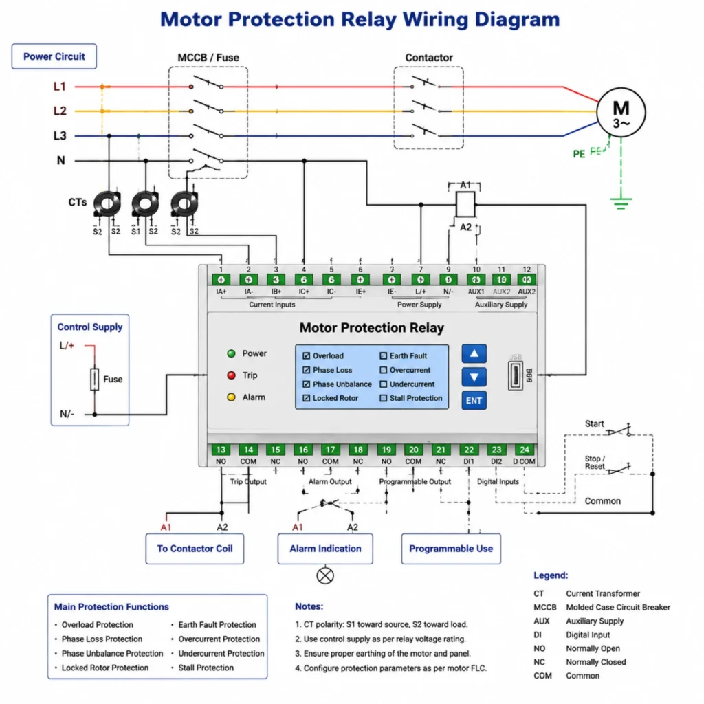
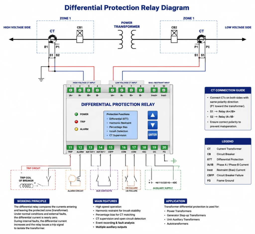
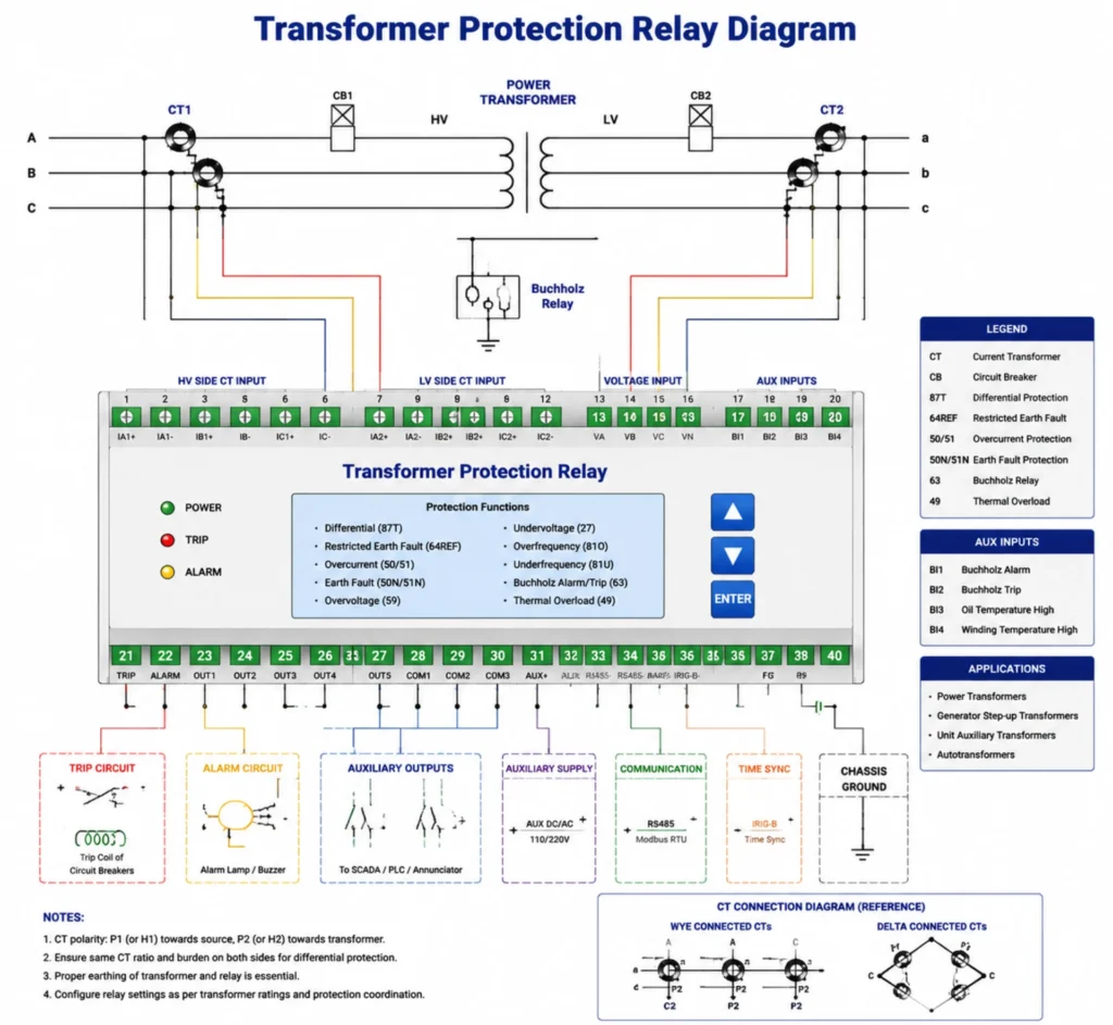
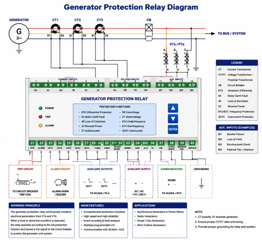
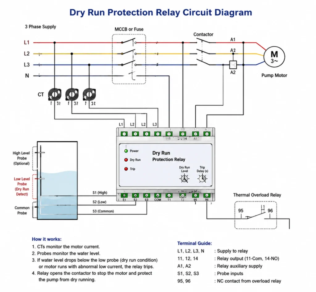
The wiring diagram is the contract between the design office and the panel builder. It shows every secondary connection: CT secondaries into the relay current inputs, VT secondaries into the voltage inputs, the trip output wiring to the breaker coil, the auxiliary supply and the alarm contacts. Read it before commissioning and again before any modification, because most site faults traced to a relay turn out to be a wiring error, not a setting error.
Five diagrams come up repeatedly in project work. Each one differs mainly in how many current inputs the relay takes and where the trip output lands.
Motor Protection Relay wiring diagram
Differential Protection Relay diagram
Transformer Protection Relay diagram
Generator Protection Relay diagram
Dry Run Protection Relay circuit diagram
Common ANSI Electrical Protection Relay Codes
Device numbers are the shorthand that lets a single-line diagram, a setting sheet and a relay menu all mean the same thing. ANSI/IEEE C37.2-2022 assigns one number per function, which is why a specification can say ANSI 51 and be understood in any country. The number describes the function, never the hardware, so a single numerical relay commonly carries ten of them at once.
Fifteen numbers appear in most industrial and utility specifications. On a setting sheet they are written as the number plus the setting, so 51 at 1.2 times rated current with a 0.4 s delay at 10 times means time overcurrent with those two values. Reading a sheet this way is faster than reading a relay menu, which is why the numbers survive every change of hardware. Where a vendor uses an IEC symbol instead, the IEC 60617 and ANSI/IEEE C37.2 notations map onto the same function, and the setting sheet should say which one it is using before anyone starts entering values.
| ANSI Code | Protection Function | Where it is applied |
|---|---|---|
| 21 | Distance Protection | Transmission and sub-transmission lines |
| 27 | Undervoltage Protection | Bus bars, motor starters, load shedding |
| 32 | Reverse Power Protection | Generator and prime mover protection |
| 40 | Loss of Excitation | Synchronous generators |
| 46 | Negative Sequence Current | Motor unbalance and lost phase |
| 49 | Thermal Overload | Motor and transformer thermal replica |
| 50 | Instantaneous Overcurrent Protection | Feeders, cables, bus sections |
| 50N | Instantaneous Earth Fault | MV networks with low impedance earthing |
| 51 | Time Overcurrent Protection | Feeders and incomers with grading |
| 50BF | Breaker Failure | Backup tripping on HV and MV boards |
| 59 | Overvoltage Protection | Generators, capacitor banks, bus bars |
| 67 | Directional Overcurrent Protection | Parallel feeders and ring mains |
| 79 | Automatic Reclosing | Overhead lines with transient faults |
| 81 | Frequency Protection | Load shedding and islanding detection |
| 87 | Differential Protection | Transformers, generators, busbars, motors |
What Are Protective Relays Used For? Four Duty Classes
Substation Protection
What are protective relays used for in a substation? Four duty classes cover it. Transformer protection uses differential and restricted earth fault on the main windings, plus Buchholz and winding temperature devices on the tank. Feeder protection uses overcurrent and earth fault, with reclosing on overhead circuits. Busbar protection compares all currents entering a bus section. Bus section and incomer protection handles the transfer logic when one source is lost.
Traditional Power Plant Protection
Provide full protection for generators, auxiliary power systems and power transmission equipment of thermal power and hydropower plants, avoiding unit shutdown accidents caused by electrical faults.
New Energy Power Station Protection
Adapt to the grid-connected protection requirements of solar power plants, wind farms and battery energy storage systems, solve the problem of fluctuating output of new energy power generation, and meet grid-connected access standards of various countries. The renewable energy relay protection range is built around that duty.
Industrial Field Protection
Widely used in oil & gas, mining, chemical industry and manufacturing plants, providing reliable power protection for high-power industrial equipment and ensuring continuous and stable industrial production.
How to Select Qualified Protective Relays for EPC & Industrial Projects?
Reasonable relay selection directly determines project safety, operation stability and later maintenance cost.
Five criteria do the work.For EPC contractors, power station owners and industrial project purchasers, follow the 5 core selection criteria:
Match System Voltage Level
Select low/medium/high voltage dedicated relays according to project voltage parameters to ensure device withstand voltage and protection accuracy meet system requirements.
Confirm Target Protection Objects
Select dedicated relays according to protection objects: transformer differential relay for transformers, motor protection relay for industrial motors, and distance relay for transmission lines to avoid mismatched protection functions.
Support Standard Communication Protocols
Priority to products supporting IEC 61850, Modbus and IEC 60870-5-103 protocols, which is convenient for system networking, remote monitoring and intelligent operation and maintenance of smart substations.
Comply with International Industry Standards
The product must pass IEC 60255 general standard certification and meet IEEE power protection specifications, with qualified EMC electromagnetic compatibility performance to adapt to complex on-site electrical environments.
Verify Supplier Engineering Service Capability
Priority to manufacturers with complete technical support capabilities, including pre-sales scheme customization, relay setting guidance, on-site commissioning and after-sales technical support, to solve on-site engineering problems efficiently.
Protective Relay Testing and Commissioning Standards
No relay goes live on trust. Commissioning proves how protective relays work against the CT and VT ratios actually wired to it, not against the settings sheet alone, and it is the step where relay protection training pays for itself. Two test levels are used, and both leave a signed record.
Common Testing Methods
Secondary injection is the routine method: the test set feeds current and voltage straight into the relay inputs and checks pickup, time delay and output contacts against the setting sheet. Primary injection pushes current through the CT primary instead, which is the only way to prove the CT ratio, the polarity and the wiring in one pass.
- Secondary injection test (mainstream routine test)
- Primary injection test
- Protection function full test
- Communication protocol compatibility test
Standard Commissioning Process
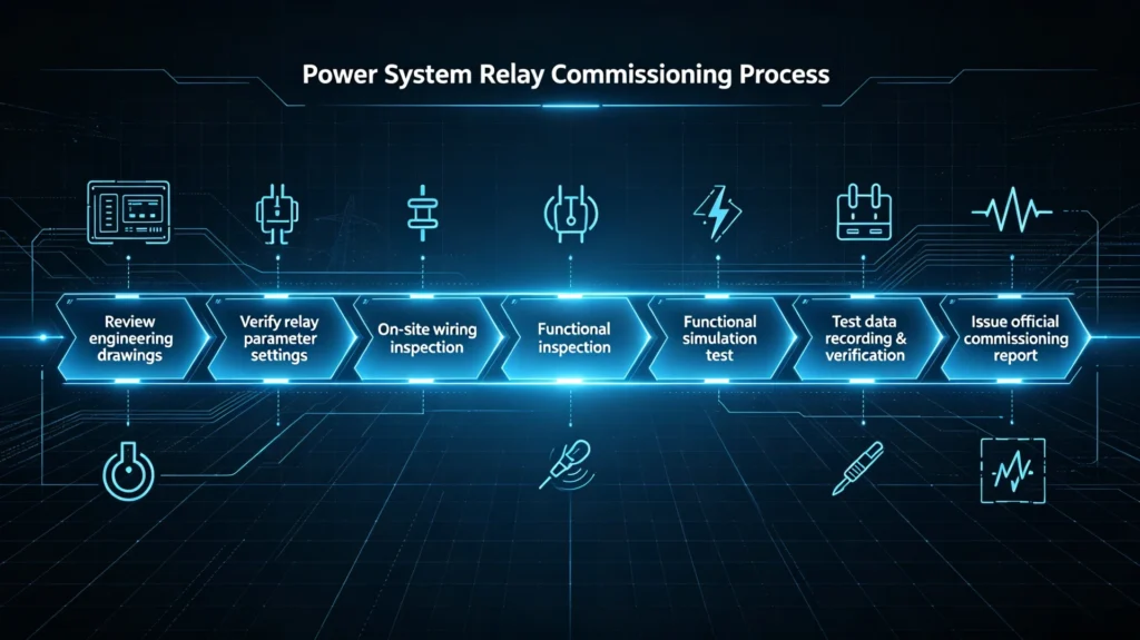
Review engineering drawings → Verify relay parameter settings → On-site wiring inspection → Functional simulation test → Test data recording & verification → Issue official commissioning report
Keep the record.
FAQ About Protective Relays
What is the main purpose of a protective relay?
Its core purpose is to detect power system electrical faults in real time, quickly isolate faulty equipment and circuits, protect power assets, keep people away from the arc, and hold the rest of the grid stable while the faulted part is switched out.
How does a protective relay detect faults?
It collects system current and voltage data through CT/PT, compares real-time operating values with preset standard thresholds, and identifies abnormal faults through built-in protection logic programs.
How often should protective relays be tested?
According to IEC and power industry operation specifications, routine calibration and testing are required every 1-2 years; full performance testing is mandatory after equipment overhaul, fault occurrence and project reconstruction. Numerical relays with continuous self monitoring can stretch that interval, but only where the utility has a written maintenance policy that says so.
What are protective relays, in plain terms?
A measuring device with a trip contact. It reads the circuit through a CT or a VT, compares the reading against a setting, and closes an output contact when the reading stays out of band for the time delay that was set. Records, communications and self monitoring all hang off that one job.
What is the protective relay definition in IEC 60255?
IEC 60255-1:2022 defines a measuring relay or protection equipment as a device that detects a fault or abnormal condition and initiates a trip or alarm. The definition is functional, not technological, so it applies equally to a 1970s induction disc and a current numerical unit.
How protective relays work with CT and VT inputs
The CT secondary feeds a current input scaled to 1 A or 5 A nominal, and the VT secondary feeds a voltage input at 100 V to 120 V nominal. The relay samples both, converts them to phasors, and compares each phasor against the setting. If the CT ratio entered in the menu does not match the ratio on the nameplate, every current based function reads wrong, which is the single most common commissioning finding.
Which protective relay types go on one feeder panel?
A typical MV feeder panel carries overcurrent and earth fault in one device, often ANSI 50, 51, 50N and 51N together. Motors add a thermal replica and negative sequence element. Incomers add directional and bus transfer logic. One numerical case usually covers the whole set.
What are protective relays on a single-line diagram?
A circle with the device number inside, drawn next to the breaker it trips. ANSI/IEEE C37.2-2022 assigns the number, so 51 on a diagram means time overcurrent to any engineer reading it, regardless of which relay was bought.
How to Check a Protective Relay Manufacturer and Supplier
Specifying the device is half the job; the other half is who stands behind it. On cross-border EPC work the supplier carries the settings, the drawings and the commissioning, so check these five points before the order goes in rather than after the container lands.
- Complete product portfolio: Cover full-series numerical protective relays for substation, power plant and industrial scenarios, supporting one-stop procurement
- Strict standard compliance: All products comply with IEC 60255, IEEE and IEC 61850 international standards, with complete certification documents
- Professional engineering team: Provide pre-sales scheme customization, parameter setting guidance, on-site commissioning and after-sales full-cycle technical support
- Flexible customization capability: Support OEM/ODM personalized development to meet the differentiated needs of different national grid standards and project scenarios
- Rich overseas project experience: Familiar with global EPC project processes and overseas grid access specifications, able to solve various on-site technical problems efficiently
Conclusion
What are protective relays worth to a project? They are the only devices on a board that turn a measurement into a decision, and they decide whether a fault costs a fuse or a transformer. From electromechanical discs to numerical units that store disturbance records, the hardware moved a long way. The job did not move at all.
For EPC contractors, power utility owners and industrial enterprise purchasers, three things decide whether the protection actually works: type selection matched to the protected object, commissioning done against the CT and VT ratios wired to the device, and settings written down where the next engineer can find them. What are protective relays worth when one of those is missing? A unit that trips correctly on a bench and stays silent on a real fault.
Everything else is detail.
Related reading
Seven pages on this site go deeper into the parts summarised above. Three of them belong to the same fundamentals cluster as this one, two cover the ANSI numbering and the numerical generation, and two explain how grading and backup protection are arranged around the main scheme. Each is written to stand on its own.
- protective relay operating principle: the sensing, measurement and comparison loop in detail
- protective relay functions: what each ANSI function does and where it is applied
- ANSI protection relay codes: the full device number list
- microprocessor based relay: the numerical generation in detail
- protective relaying principles and applications: grading, selectivity and backup
- backup protection relay: what covers the main protection when it fails
- protective relays in the utility market: how utility practice differs from industrial
Reference and Technical Sources
Every standard named on this page is listed below with the edition in force and the part of the job it governs. Where an EN version differs in year from the IEC original, both are given.
| Source | Edition | What it fixes | Where it applies |
|---|---|---|---|
| IEC 60255-1 | 2022 | Common requirements: accuracy, burden, response, type and routine tests | Every relay specification |
| IEC 60255-26 | 2023 (EN IEC 60255-26:2025) | Electromagnetic immunity for measuring relays | Substation and switchgear environments |
| IEC 60255-27 | 2023 | Product safety up to 1 000 V AC and 1 500 V DC | Enclosure, insulation and clearances |
| IEC 60255-151 | 2009 | Functional requirements for overcurrent | ANSI 50 and 51 elements |
| IEC 60255-187-1 | 2021 | Functional requirements for differential | ANSI 87T, 87G and 87M |
| IEC 60255-149 | 2013 | Thermal replica function | ANSI 49 motor overload |
| ANSI/IEEE C37.2 | 2022 | Device numbers and function names | Single-line diagrams and setting sheets |
| IEEE C37.90.1 | 2024 | Surge withstand and electrical fast transient | Relay inputs in HV yards |
| IEEE C37.90.2 | 2024 | Radiated RF immunity, 80 MHz to 6 GHz | Relay cases near radio sources |
| IEC 61850-8-1 | 2011+AMD1:2020 | Station bus mapping and GOOSE messaging | Substation automation |
| IEC 60870-5-103 | 1997 | Serial interface to protection equipment | Retrofit and legacy bays |
| IEC 61869-2 | 2012 | Current transformer accuracy class and rating | CT selection for the relay input |
| IEC 61508 | 2010 | Functional safety lifecycle and SIL | Safety related interlocks |
Older editions still appear in project specifications from time to time. IEC 60255-1 was last revised in 2022 and IEC 60255-26 in 2023, so a specification citing the 2013 EMC edition is citing a withdrawn document.



About Author

Hello, I'm Leno Zhang. I have 15 years of experience in the power relay protection industry with extensive pre-sales and after-sales project experience. Our company specializes in various complete sets of relay protection and automation equipment. I can assist customers in solving all practical on-site project challenges and provide optimal integrated solutions.
Tell Us Your Requirement
High Quality
Stable performance, reliable design, ensuring safe operation for power system protection and grid stability.
Fast Delivery
Timely delivery to support your urgent orders and project schedules efficiently and professionally at any time.
Best Warranty
Professional Warranty: Reliable after-sales support for stable relay protection and long-term customer satisfaction.