

-
Leon Zhang sales consultant
-
Email: zxl635973785@gmail.com
-
Phone/WhatsApp: +86 13655813266
How to Select a Motor Protection Relay? A Practical Selection Guide
Introduction: Why Motor Protection Relay Selection Matters
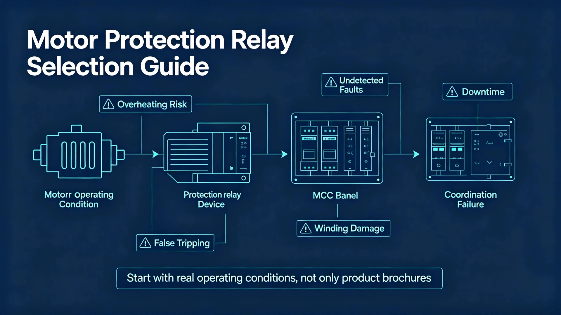
Improper motor protection relay selection creates avoidable risks for industrial facilities, EPC projects, and motor control centers. Common consequences include motor overheating, nuisance tripping, undetected phase‑to‑phase faults, permanent winding damage, unplanned downtime, and poor time‑current coordination with upstream protective devices.
For EPC contractors and plant owners, mis‑specified relays lead to site rework, warranty claims, and extended project commissioning. The motor protection relay selection process should start with real‑world motor operating conditions rather than product brochures. This practical guide walks you through each decision point for reliable motor relay selection.
What Is a Motor Protection Relay?
A motor protection relay is a dedicated protective device monitoring motor current, voltage, and auxiliary signals to detect abnormal operating conditions and trip the motor circuit before permanent damage occurs.
What Does a Motor Protection Relay Protect Against?
Modern digital motor protection relays cover the following typical fault and abnormal operating conditions:
- Overload
- Short‑circuit
- Phase loss
- Phase unbalance / negative‑sequence current
- Locked rotor
- Motor stall
- Earth / ground fault
- Underload (dry‑run detection for pumps)
- Overvoltage & undervoltage
- Overtemperature (PT100/PTC winding sensor input)
Motor Protection Relay vs. Thermal Overload Relay
Many projects still use thermal overload relays for basic motor protection. The table below compares core capabilities:
| Feature | Motor Protection Relay | Thermal Overload Relay |
|---|---|---|
| Overload protection | ✓ | ✓ |
| Phase‑loss detection | ✓ | Limited performance |
| Current unbalance protection | ✓ | Limited |
| Earth fault protection | ✓ | Usually not available |
| Underload monitoring | ✓ | No |
| Motor condition monitoring | Advanced diagnostics | Basic only |
| Communication interface | Available on most digital units | Rare / very limited |
How to Select a Motor Protection Relay: 8‑Step Selection Process
This 8‑step workflow is the core for motor protection relay selection. Follow these steps sequentially for your motor relay selection.
Start With the Motor Nameplate Data
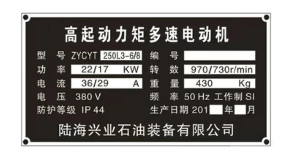
Always extract key parameters directly from the motor nameplate, not only power rating:
- Rated power (kW / HP)
- Rated operating voltage
- Full‑Load‑Amperes (FLA, rated motor current)
- Nominal frequency
- Power factor
- Motor efficiency
- Locked‑rotor / starting current
- Service factor
- Stator winding connection (Delta / Wye)
Critical note: Relay sizing shall be based on motor FLA, not kW or HP only. Two motors with identical power rating can have very different full‑load current depending on voltage, efficiency and pole count.
Check the Motor Voltage and Current Range
Match hardware specifications against your system:
- Relay auxiliary supply voltage
- Measuring current input range (direct input or CT‑connected)
- CT rated ratio (for high‑current motors)
- System operating frequency (50 Hz / 60 Hz)
Logical sequence for sizing:
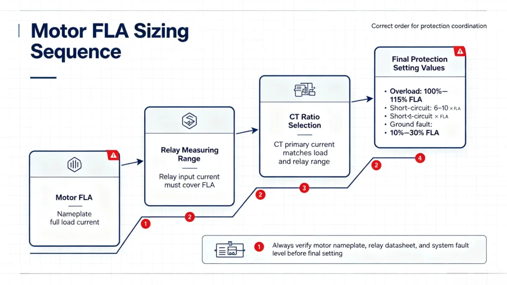
Motor FLA → Relay measuring range → CT ratio selection → Final protection setting values
Example: For a 320 A full‑load current motor, select CT ratio and relay measuring input to provide adequate measurement range while preserving fault‑detection sensitivity.
Determine Which Motor Protection Functions You Need
Match protection functions to application requirements. ANSI device numbers are widely used in international EPC projects.
| Protection Function (ANSI) | Typical Application Requirement |
|---|---|
| Overload (49) | Almost all induction motors |
| Short‑circuit (50 / 51) | General motor feeder protection |
| Phase loss | Three‑phase industrial motors |
| Phase unbalance / Negative‑sequence (46) | Sensitive, high‑value motors |
| Locked rotor | High‑inertia driven loads |
| Stall protection | Long acceleration‑time motors |
| Earth fault (50N / 51N) | Ground‑fault risk environments |
| Under‑current | Pumps, fans for dry‑run detection |
| Overtemperature (49T) | Critical process motors with winding temperature sensors |
Explore more motor protection functions
Consider the Motor Starting Method
Motor starting behaviour directly affects relay setting logic. The relay must ride through valid starting inrush current while still detecting genuine locked‑rotor or stall faults.
Direct‑On‑Line (DOL) Starting
High inrush (5‑7 × FLA). Relay acceleration timer must cover full motor ramp‑up duration.
Star‑Delta Starting
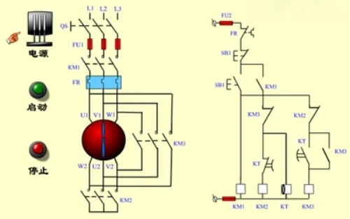
Lower initial starting current; pay attention to unbalance risk during transition phase.
Soft Starter
Smooth ramp‑up; monitor for stall conditions during soft‑start sequence.
Variable Frequency Drive (VFD)
VFD‑fed motors generate harmonic components. Confirm relay hardware suitability for distorted current waveforms.
Key rule: A motor protection relay should NOT nuisance‑trip during normal motor starting, but must reliably detect locked‑rotor and stall events.
Consider the Motor Load and Application
Different load types create distinct fault patterns. Below table maps typical applications and priority protection features:
| Motor Application | Key Required Protection |
|---|---|
| Pump | Overload, under‑current (dry‑run), phase loss |
| Fan | Overload, phase loss, phase unbalance |
| Compressor | Overload, locked‑rotor, winding overtemperature |
| Conveyor | Overload, stall protection, phase loss |
| Crusher | Locked‑rotor, stall, heavy overload |
| HVAC motor | Overload, phase loss, unbalance |
| Critical industrial process motor | Full protection suite + data communication |
Check CT Ratio and Current Transformer Compatibility
For motors above approximately 100 A, current transformers are required to step‑down primary current to relay secondary measuring inputs (typically 1 A or 5 A). This topic is frequently overlooked in tender specification work by EPC teams.
When Do You Need CTs?
When motor FLA exceeds the relay’s built‑in direct‑input maximum current.
How to Select the CT Ratio
CT primary rating should cover maximum continuous motor operating current plus service‑factor margin. Avoid oversized CT ratios that reduce low‑magnitude fault sensitivity.
CT Accuracy and Burden
Confirm CT accuracy class and burden rating match relay input burden requirements, otherwise measurement error will degrade protection performance.
Relay CT‑Input Compatibility
Verify relay supports your selected secondary rating: 1 A or 5 A CT secondary.
Practical example: 320 A motor FLA → select 400/5 A CT; ensure relay 5 A CT‑input hardware variant is ordered.
Check Protection Relay Setting Requirements
Hardware nominal current range is not equal to usable setting range. Verify adjustable parameter coverage before purchase:
- Overload setting range & trip class
- Instantaneous / time‑delayed overcurrent setting
- Earth‑fault threshold range
- Phase‑unbalance threshold
- Undervoltage / overvoltage thresholds
- Motor acceleration time timer
- Trip delay timers
- Manual / automatic reset mode
Important concept: Motor FLA ≠ protection setting value. Settings must include margin for service factor, operating fluctuations and starting conditions.
Consider Communication and Monitoring Requirements
Define monitoring and system integration needs during motor relay selection phase.
Local‑Only Protection
Suitable for small motors, simple MCC panels, basic industrial workshops. No remote data required.
Motor Protection + Communication
Mandatory for large plants, automated MCC, pump stations, water‑treatment, oil‑gas and power‑plant auxiliaries. Common supported protocols:
- Modbus‑RTU
- Modbus‑TCP
- IEC 61850
- Ethernet
- Profibus
If SCADA or PLC integration is required, confirm protocol support at specification stage. Adding communication after commissioning is costly and often impossible with existing hardware.
Digital vs. Electromechanical Motor Protection Relays
| Feature | Digital Motor Protection Relay | Electromechanical Relay |
|---|---|---|
| Protection functions | Multiple configurable functions | Very limited function set |
| Measurement | High‑resolution digital measurement | Basic electromagnetic measurement |
| Event records / fault logs | Yes, timestamped fault history | Usually none |
| Communication interface | Available | Rare |
| Parameter settings | Flexible software configuration | Limited mechanical adjustment |
| Built‑in diagnostics | Advanced motor health diagnostics | Minimal diagnostics |
For new‑build industrial projects and automated MCCs, digital motor protection relays are generally preferred. Electromechanical devices remain acceptable for low‑cost simple retrofit tasks.
Motor Protection Relay Selection by Application
How to Select a Relay for a Pump Motor
Prioritise under‑current / dry‑run protection besides standard overload and phase‑loss. Specify earth‑fault if pump is submerged.
How to Select a Relay for a Compressor Motor
Locked‑rotor and thermal overload are high‑priority. Consider winding temperature input for heavy‑duty cyclic compressors.
How to Select a Relay for a Fan Motor
Phase unbalance and phase loss are critical. Some large fans feature long acceleration times; configure stall and extended acceleration timer.
How to Select a Relay for a Conveyor Motor
Stall protection and locked‑rotor functions are essential for jam conditions.
How to Select a Relay for a Large Industrial Motor
Deploy full‑featured digital relay, CT‑input, communication for SCADA integration, full fault event logging, and full protection suite including negative‑sequence and earth‑fault protection.
Common Motor Protection Relay Selection Mistakes
These mistakes regularly appear in tender specifications and site commissioning reports. Avoid them during your motor relay selection:
- Select relay only by motor kW / HP rating: Always reference FLA nameplate value.
- Ignoring motor starting current: Nuisance tripping occurs if acceleration timer is insufficient.
- Choosing incorrect CT ratio: Oversized CT reduces ground‑fault sensitivity.
- Skipping verification of setting range: Hardware nominal current may not cover your required setting window.
- Ignoring phase‑unbalance risk: Damages motor windings under single‑phase supply degradation.
- Applying identical settings across different motor loads: Pumps, crushers and conveyors require different parameter sets.
- Neglecting communication requirements: Cannot integrate with SCADA after hardware delivery.
- Ignoring system protection coordination: Relay must coordinate with MCCB, ACB, upstream feeder protection and contactor characteristics.
Motor Protection Relay Coordination
Motor protection relays do not operate in isolation. Proper selective coordination ensures only the faulted motor circuit trips, without cascading upstream outages across MCC or plant distribution systems.
Devices involved in coordination study:
- Motor protection relay
- MCCB / ACB
- Power fuses
- Upstream feeder protective relay
- Contactor
- Backup thermal overload devices
What is selective coordination? Selective coordination means that for a given fault, the closest protective device to the fault operates first, upstream devices remain intact. Time‑current curves and time‑grade margins (typically ≥0.3 s time difference) are applied to achieve selectivity.
Why coordination matters: Poor coordination creates widespread plant shutdown triggered by a single motor fault. This is a major pain‑point for EPC contractors and end‑users.
Motor Protection Relay Selection Checklist
Copy‑paste this checklist for your tender specification or internal engineering review.
Motor Data
- Motor rated power
- Rated operating voltage
- Full‑Load‑Amperes (FLA)
- Operating frequency
- Starting method
- Starting / locked‑rotor current
- Load application type
Protection Requirements
- Overload (49)
- Short‑circuit (50/51)
- Phase loss
- Phase unbalance / negative‑sequence (46)
- Earth‑fault (50N/51N)
- Locked‑rotor protection
- Stall protection
- Under‑current / dry‑run
- Winding overtemperature (49T)
Relay Hardware Requirements
- Current‑input type: direct input or CT‑input (1 A / 5 A secondary)
- CT ratio selected
- Required setting‑range coverage
- Trip‑class requirements
- Communication protocol
- Digital input / output quantity
- Event‑recording capability
- Installation form (DIN‑rail / panel mount)
Frequently Asked Questions
Q1: What is the best motor protection relay?
There is no universal “best” model. The best unit matches your motor nameplate data, required protection functions, starting method, load characteristics, CT parameters and communication needs.
Q2: How do I select a motor protection relay?
Follow the 8‑step workflow in this guide: collect motor nameplate data → define required protection → evaluate starting mode → load type → CT compatibility → setting range → communication → protection coordination.
Q3: What protection does a motor protection relay provide?
Typical functions include overload, short‑circuit, phase loss, phase unbalance, locked rotor, stall, earth‑fault, underload and winding temperature monitoring.
Q4: What size motor protection relay do I need?
Size based on motor FLA, not kW. Choose relay measuring range covering FLA plus service‑factor margin. For higher‑current motors select matching CT ratio.
Q5: Do I need a CT for a motor protection relay?
CTs are required when motor full‑load current exceeds relay direct‑input maximum rating, common for motors >100 A.
Q6: What is the difference between a motor relay and an overload relay?
Thermal overload relays offer mainly basic overload and limited phase‑loss protection. Digital motor protection relays deliver comprehensive fault detection, flexible settings, diagnostics and communication capability.
Final Recommendation: How to Choose the Right Motor Protection Relay
Stick to this decision workflow for every project: Motor Nameplate Data → Starting Method → Load Application → Required Protection Functions → CT / Input Hardware → Adjustable Setting Ranges → Communication Requirements → System‑level Protection Coordination → Final Relay Selection
If you are specifying a motor protection relay for an EPC or industrial project, prepare and share these key parameters with your supplier: motor rated power, operating voltage, full‑load‑current, starting method, CT ratio and required protection functions. With this information, suppliers can deliver precise and technically compliant recommendations rather than generic product suggestions.
Call‑to‑action: Our engineering team supports EPC contractors and system integrators with motor protection relay specification review, parameter validation and application consultation. Send your motor datasheets for technical evaluation.
References & Technical Sources (for EEAT compliance)
- IEC 60947‑4‑1: Low‑voltage switchgear and controlgear – Contactors and motor‑starters
- IEEE Std C37.112: Standard Inverse‑Time Characteristic Curves for Overcurrent Relays
- IEEE Std C57.13.1: Application guide for instrument transformers
- ANSI / IEEE device‑number standard for protective relay functions
- IEC 61850: Communication networks and systems for power utility automation



About Author

Hello, I'm Leno Zhang. I have 15 years of experience in the power relay protection industry with extensive pre-sales and after-sales project experience. Our company specializes in various complete sets of relay protection and automation equipment. I can assist customers in solving all practical on-site project challenges and provide optimal integrated solutions.
Tell Us Your Requirement
High Quality
Stable performance, reliable design, ensuring safe operation for power system protection and grid stability.
Fast Delivery
Timely delivery to support your urgent orders and project schedules efficiently and professionally at any time.
Best Warranty
Professional Warranty: Reliable after-sales support for stable relay protection and long-term customer satisfaction.