
-
Leon Zhang Sales Manager
-
Email: sale@relayprotect.com
-
Phone/WhatsApp: +86 13655813266
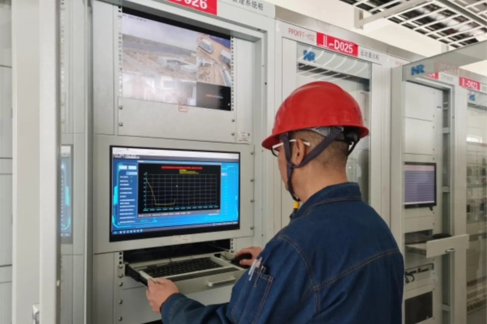
Substation: Classes, Equipment and Busbar Schemes
What classes of substation are there and what do they contain?
A substation is a fenced compound where voltage is stepped up or down, power flows are switched, and relays watch every feeder. Transmission yards work at 220, 400 and 765 kV, distribution networks at 132, 110, 66, 35 and 11 kV, and a factory may need only one 20 kV intake. The equipment classes repeat at every size, which is why one guide can cover them all. The job reduces to three verbs: transform, switch, protect. A 30 MVA flow at 110 kV draws about 157 A, while the same flow at 11 kV would draw 1,574 A and cook the conductors. Land is the other currency: a 110 kV air-insulated yard needs 8 to 10 m bay spacing, while SF6 gas-insulated enclosures collapse clearances to centimetres at roughly twice the cost per bay. Fault clearing belongs to relays per IEC 60255-1:2022 and ANSI/IEEE C37.2-2022. Setting review and quotation within 12 hours, MOQ 1, 7-15 working days.
Substation is the general name for a fenced compound where voltage is stepped up or down, power flows are switched, and relays watch every feeder: transmission yards work at 220, 400 and 765 kV, distribution networks run at 132, 110, 66, 35 and 11 kV, and a factory often needs only one 20 kV intake. The equipment classes repeat at every size, which is why one guide can cover all of them.
Two boundaries hold the page honest. Fault clearing belongs to the protection relays per IEC 60255-1:2022, labelled by the device numbers of ANSI/IEEE C37.2-2022; the yard is their habitat, not their replacement. Supervision and telecontrol belong to the layer described in the SCADA systems; this page stops at the station boundary.
Everything below is the map view. Depth lives in the dedicated pages: digital fault recorders, 22 kV feeder protection, substation communication protocols and the ATN-400 automation system each get a full article. Here the aim is the whole elephant: what the classes are, what the six primary devices do, why busbar arrangement decides reliability, and what belongs in a specification.
Written by Leon Zhang, Protection Application Engineer · Technical review by the relayprotect.com engineering team · Last reviewed October 2026

At a Glance: Numbers That Decide a Design
- An air-insulated 132 kV yard needs 1 to 2 hectares; gas-insulated switchgear squeezes the same circuits into roughly 10% of that footprint.
- Breakers rated 31.5 kA or 40 kA symmetrical cover most 110 kV fault levels, but the calculated duty, not habit, must set the rating.
- Transformer impedances of 8 to 14% limit fault current; the exact value trades protection margin against voltage sag, and it is a design choice.
- An on-load tap changer adds ±8 steps of 1.25%, enough to hold a 33 kV busbar inside ±1% through the daily load swing.
- Protection CTs carry a 5P20 label; metering CTs carry 0.2S. Fitting the wrong class is the classic commissioning error.
- GOOSE messages cross a bay in about 4 ms on IEC 61850-8-1:2011+AMD1:2020, far inside any breaker operating time.
- 110 V or 220 V DC batteries carry trip power for hours; a capacity test every two years keeps them honest.
- IEC 61936-1:2021 collects the design rules for installations above 1 kV, so the RFQ can cite one document for the civil and electrical envelope.
What Is a Substation and What Does It Change?
The job reduces to three verbs: transform, switch, protect. Transformers move power between voltage levels because losses fall as voltage rises; a 30 MVA flow at 110 kV draws about 157 A, while the same flow at 11 kV would draw 1,574 A and cook the conductors. Switchgear routes that power, isolates equipment for maintenance, and clears faults. Protection measures everything and trips when the arithmetic goes wrong.
Voltage is the currency of distance. Generation steps up to 220 to 765 kV because a 500 km line at 400 kV loses a few percent of its energy, while the same power pushed at 35 kV would lose most of it as heat.
Selecting a relay for a live project?
Send the system voltage, CT ratio and tripping scheme. Our engineers confirm the model and reply within 12 hours.
The wire is the same copper; what changes is the electric stress it is allowed to carry.
Land is the other currency. A yard at 110 kV built with open-air equipment needs bay spacing of 8 to 10 m for insulation clearances, which is where the hectare figure comes from. Put the same busbars inside SF6-filled metal enclosures and the clearances collapse to centimetres.
Neither option is free: gas-insulated gear costs roughly twice as much per bay and needs gas handling discipline for the next forty years.

Classes of Electric Substation: From Switchyard to Package Unit
Where a site sits in the power chain decides its class, and the class predicts everything: equipment ratings, land take, staffing, budget. A 500/220 kV transmission hub is a different universe from a two-transformer distribution site behind a shopping centre, yet both appear in the same tender inboxes.
| Class | Typical voltages | Job in the chain | What dominates the cost |
|---|---|---|---|
| Step-up (power plant) | 13.8 to 765 kV | Raise generator voltage for transmission | Generator step-up transformers, bus ducts |
| Transmission hub | 220 to 765 kV | Interconnect lines, route bulk power | Breakers, land, civil works |
| Primary distribution | 110/132 kV to 33 kV | Feed a city district or industrial park | Two or three power transformers |
| Secondary distribution | 33/35 kV to 11/20 kV | Distribute inside a plant or town | Switchgear bays, RMUs |
| Switching station | Any HV | Route and sectionalize, no transformation | Breakers and disconnectors only |
| Package / unit | 20 kV to 0.4 kV | Serve one load point, wind or solar farm | Transformer plus ring main unit in one skid |
The last row explains most cost surprises. When a load needs 1 MVA and one feeder, a package unit with a ring main unit does the whole job on a concrete pad. Building a fenced bay instead buys land, roads, a control room and a fencing contract for the same electrons.
What Is the Substation Doing Between Faults?
Faults are rare. The yard earns its keep on ordinary days, and four duties repeat hourly. Voltage regulation: the on-load tap changer steps up or down to hold the LV busbar inside its band as load climbs through the afternoon. Reactive support: capacitor banks and reactor banks are switched in and out to hold power factor near unity and keep voltage stable at the far end of the feeders.
Load transfer: operators (or the automation, on good days) reconfigure busbars so that maintenance takes one circuit out without dropping a single customer. That is what the bus coupler and the bypass disconnector in Figure 2 are for. Measurement and billing: the 0.2S metering CTs and their voltage transformers feed revenue meters whose readings settle contracts worth more than the entire yard.
Condition watching rounds out the list. Oil and winding temperatures, SF6 gas density, battery voltage, trip-circuit supervision, door and flood alarms: all of it lands in the monitoring screens described in the SCADA guide. A quiet day is the success condition, and the design question is whether the quiet day is being watched honestly.
Primary Equipment: The Devices That Do the Work
Six device classes cover the yard, and every specification is a list of six with quantities. The transformer converts voltage. The circuit breaker interrupts current, including the worst fault current the network can deliver. The disconnector isolates for maintenance, with a visible break but no breaking ability. The current and voltage transformers scale kiloamps and hundreds of kilovolts down to signals a relay can read. The surge arrester clamps lightning and switching surges.
The busbar and its insulators connect it all.
Two of the six deserve closer numbers. Breakers per IEC 62271-100:2021 carry ratings that read like a sentence: 40 kA symmetrical breaking current, 63 kA peak making current, 2,000 A continuous, operating time of two to three power-frequency cycles, which is 40 to 60 ms from trip coil energized to current zero.
That speed is what limits equipment damage; every additional cycle lets fault energy cook the busbar a little longer.
Disconnectors have no such talent. They change position only when no current flows, which is why the interlock scheme (the “five preventions” familiar from Chinese practice: no trip without authority, no close onto earth, no open under load, no enter while live, no wrong bay) is wired into the mechanism rather than written into a procedure.
A disconnector operated against the interlock is how busbars die.
Transformers: The Largest Line Item
A power transformer is 30 to 45% of a distribution yard’s budget, and its nameplate tells the whole story of the site. The unit in Figure 3 reads: 30 MVA, 20/6.3 kV, impedance near 10%, Dyn1 vector group, ONAN cooling, on-load tapping across 17 steps. Each entry is a decision that the design made and the wallet paid for.
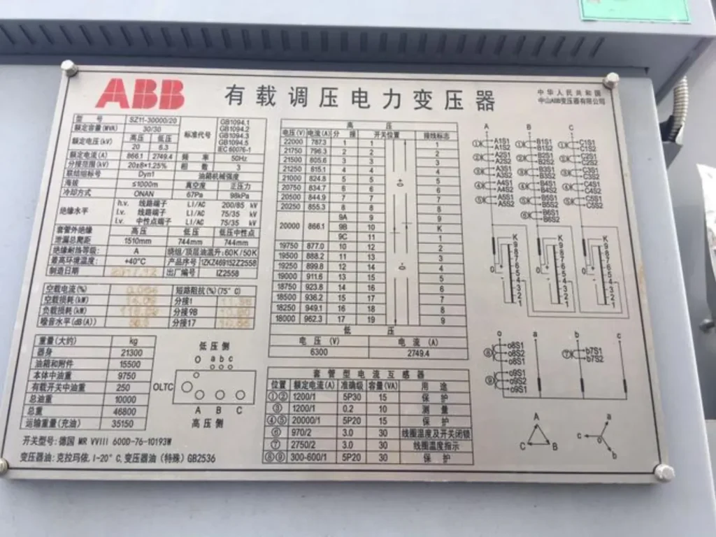
Impedance is the least understood entry. Raise it and fault currents fall, protecting downstream gear; raise it too far and voltage sag under motor starting becomes a complaint generator. Ten percent is a defensible default at 30 MVA, and IEC 60076-1:2011 defines the tolerances within which the factory may deliver it.
Cooling class predicts the maintenance bill. ONAN (oil natural, air natural) runs silent and has almost nothing to service. ONAF adds fans, which add a fan maintenance contract.
ODAF adds oil pumps as well, and a transformer that trips on low oil flow stops being a transformer until the pump is fixed. Choose the cooling class from the load profile, not from a catalogue habit.
Failures cluster in three places, and each has a leading indicator. Winding insulation ages with moisture and heat, which dissolved-gas analysis of the oil tracks months ahead. Tap changer contacts erode, which drive-current signatures show. Bushings crack, which power-factor tests catch at annual inspection. The transformer protection schemes page turns each of these into relay settings.
Busbar Arrangements: Where Reliability Is Bought
Busbar layout is the closest thing the trade has to an honesty test, because it prices reliability directly. Every arrangement below is a bet on how often things fail and what a lost busbar costs.
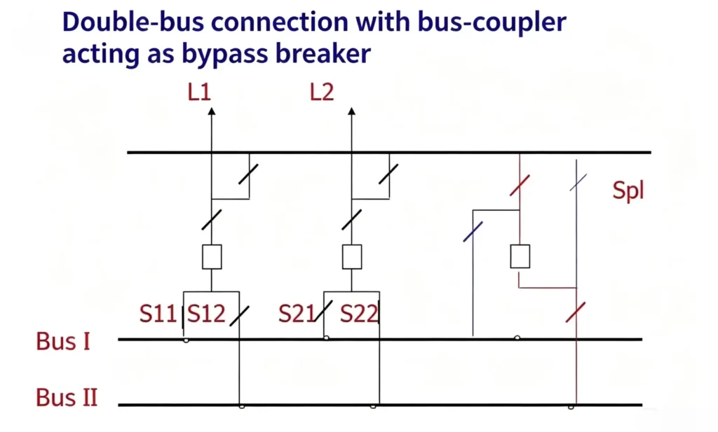
| Arrangement | Breakers per circuit | What one bus fault costs | Where it fits |
|---|---|---|---|
| Single bus | 1 | Everything on the bus trips | Small industrial sites, package units |
| Sectionalized single bus | 1 + tie | Half the bus trips | Plants that can shed one half |
| Double bus, single breaker | 1 | Feeder stays up via bus transfer | Primary distribution, 110/132 kV |
| Ring bus | 1 | Loops around the lost section | Two to six circuits, high reliability per yuan |
| Breaker-and-a-half | 1.5 | Nothing trips; both buses stay live | Transmission hubs, 220 kV and up |
The breaker-and-a-half arrangement is the reliability ceiling: two buses, three breakers per two circuits, and no single failure that drops a circuit.
The price is the ceiling too, which is why 500 kV hubs buy it and 20 kV feeders sensibly do not. Ring buses sit in the middle and are the most argued-about layout in the trade, because adding the seventh circuit to a six-position ring is exactly the moment someone should have chosen a different topology.
Instrument Transformers: Why CT Class and Polarity Decide Everything
Every protection decision is only as good as the current and voltage signals behind it, and the instrument transformers are where most silent mistakes live. A CT rated 5P20 keeps its ratio error under 5% up to 20 times rated current; that headroom is what survives the first cycle of a fault, when the CT core is asked to reproduce a waveform that is trying to saturate it.
A 0.2S metering core is accurate to a fraction of a percent at load current and saturates almost immediately in a fault. The two look identical from outside and are not interchangeable.
Polarity is the second trap. Differential protection, directional elements and busbar zones all assume the P1 terminal faces the bus and the S1 terminal feeds the relay with a defined sign. Reverse one CT pair and the 87T element reads through-faults as internal ones. Hundreds of commissioning hours have been spent hunting a “relay problem” that was a CT wired backwards behind a terminal block.
The third trap is the open secondary. A CT with its secondary open develops hundreds of volts across the terminals, enough to injure and enough to destroy the core’s magnetization.
Shorting blocks exist for a reason, and the rule about never opening a CT circuit under load belongs in the operating procedures, not in folklore.
Protection and Control Inside the Control Building
The control building holds the second half of the design. Protection panels carry the numerical relays, one per bay at minimum, each combining the ANSI function numbers (50/51 overcurrent, 87 differential, 21 distance, 25 synchronization) described on the ANSI device number chart. Duplication is standard above 110 kV: main-one and main-two relays from different principles or manufacturers, each with its own CT core and trip coil, so that one relay’s failure cannot strand a fault.
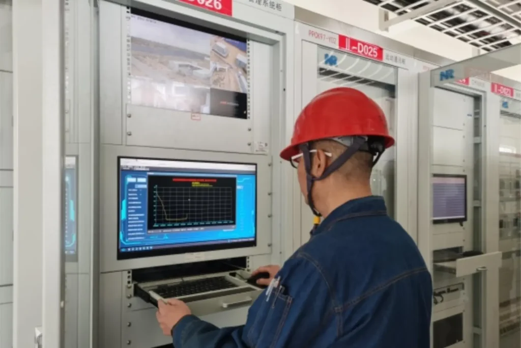
DC power is the part visitors overlook. Tripping must work when AC is gone, so 110 V or 220 V battery banks feed the trip coils and the relays directly. Battery health is a maintenance discipline: float voltage daily, capacity test every two years, and treat the charger’s alarm contacts as protection equipment, because a silent charger failure has a way of announcing itself during the first fault after it happens.
Station-level wiring has largely moved onto fibre. IEC 61850-8-1:2011+AMD1:2020 defines the MMS reporting between bay and station levels, and GOOSE peer-to-peer messages move interlock and blocking signals between bays in about 4 ms, without waiting for a master. The communication architecture, gateways and the RTU uplink are covered in the protocol comparison and in the ATN-400 system introduction.
Testing discipline closes the design. A structured commissioning program proves every trip path with secondary injection, then primary injection where the ratings justify it, and leaves signed records per point. The cheapest failure to fix is the one caught at FAT.
Earthing and Step Voltage: The Design Nobody Sees
Below grade sits the grounding grid, typically a lattice of flat steel or copper buried 0.6 to 0.8 m deep, and its job is to keep touch and step voltages survivable when a fault dumps thousands of amperes into the soil.
Soil resistivity surveys drive the design; a 110 kV site on low-resistivity soil may reach below 1 ohm, while a rocky site fights for 5 ohms and buys the difference with more conductor, a deeper grid or a surface layer of high-resistivity gravel.
The two numbers that matter are touch voltage (hand to feet) and step voltage (foot to foot), and they are calculated, not guessed. Grid corrosion is the silent failure: a grid installed in aggressive soil without cathodic protection may have lost half its conductor cross-section after twenty years, and the first hint arrives as an unexpectedly high rise-of-earth-potential during a fault test.
Lightning protection completes the envelope. Shield wires and mast height are set so that the protected equipment sits inside the rolling-sphere radius for its insulation class, and surge arresters at each transformer terminal clamp what slips through. Arrester counters are read at every inspection because a rising count is the yard telling you something about its neighbourhood.
Air-Insulated, Gas-Insulated or Prefabricated: Choosing the Layout
Three build styles cover nearly every project, and the choice is usually settled by land and by climate rather than by electricity.
| Style | Land take | Unit cost | Wins when |
|---|---|---|---|
| AIS (air-insulated, open air) | 1.0 (reference) | 1.0 | Land is cheap, climate is mild, space for maintenance access exists |
| GIS (gas-insulated, metal-enclosed) | 0.1 to 0.3 | 1.8 to 2.5 | Urban land, harsh or salty air, seismic zones, height limits |
| Hybrid (HIS/HGIS) | 0.3 to 0.5 | 1.3 to 1.6 | Breakers and CTs sealed, buses open air |
| Prefabricated package | Pad only | 0.5 to 0.8 per MVA served | Single load points, wind and solar collector sites, fast delivery |
GIS deserves one caution beyond price: every gas compartment is a pressure vessel with an SF6 inventory, and density monitors are safety devices, not conveniences. A site that accepts GIS is also accepting a gas-handling procedure, Leak detection at annual inspection, and end-of-life gas recovery. Budget the procedure on day one, because retrofitting discipline costs more than specifying it.
Prefabricated package units invert the logic: the factory wires and tests the transformer, RMU, LV board and protection as one skid, so site work reduces to foundations, cable termination and one acceptance test. For a 1 to 2.5 MVA load point this is nearly always the fastest and cheapest route, and the panel supply case studies show the same factory-tested logic scaled up to full 110 kV projects.
What Belongs in the Specification
A specification that names the envelope, the devices and the acceptance tests collects comparable bids. The items that decide the outcome:
- Rated voltages, highest system voltage and insulation levels (BIL) per voltage class, plus the site altitude, because clearances above 1,000 m need correction.
- Short-circuit duty: calculated symmetrical breaking current and peak making current at each busbar, with the network study attached.
- Transformer ratings: MVA pairs (ONAN/ONAF), impedance with tolerance, vector group, tap range and step size, cooling class.
- Busbar arrangement with the single-line diagram, and the bus transfer philosophy in writing.
- Instrument transformer classes per function: 5P20 or better for protection cores, 0.2S for revenue metering, with ratios and burdens listed per bay.
- DC system: battery voltage, autonomy time (commonly 2 to 5 hours), charger configuration and capacity test interval.
- Protection philosophy: main-one and main-two sets, tripping logic, interlock scheme, and the records each relay must keep.
- Communication: protocol per interface (IEC 61850, IEC 60870-5-104, DNP3), point counts and the gateway buffering requirement.
- Acceptance: FAT on real hardware with point-to-point sheets, then SAT on site, with the relay setting files delivered as run-ready versions.
- Spares: which breaker poles, relay modules and battery cells are stocked, for how long, at what response time.
The last item is the one that ages best. A yard is a thirty-year asset wearing out at different rates, and the spares list is where the operator decides whether year twelve is a phone call or a procurement project.
When a Substation Is the Wrong Answer
Not every load point deserves a fenced site. Five situations regularly produce over-built designs:
- One feeder, one load. A ring main unit plus package transformer serves 1 to 2.5 MVA on a concrete pad; a gated yard for that load is municipal vanity.
- The load already sits behind an intake. Adding a panel inside the existing installation is a retrofit; building a new site to avoid a cable is a career-limiting decision.
- Temporary or seasonal loads. Skid-mounted units move, fenced sites do not, and a three-year load does not amortize civil works.
- Pure switching duty. When no voltage change is needed, a switching station with breakers and disconnectors is the correct, cheaper scope; bolting a transformer onto it adds losses and alarms nobody asked for.
- Generation that consumes its own output. A PV plant whose load sits behind the same meter has no network connection to defend, and the grid-connected cases are the ones that need the yard at all.
The pattern behind all five: build the site when the network connection requires it, not because the load is large. Bigness is not a boundary condition; topology is.
Frequently Asked Questions
What does a substation do?
Three jobs: it transforms power between voltage levels, switches circuits and busbars to route that power, and houses the protection that detects and clears faults on every feeder leaving the site.
What is the difference between a substation and a switchyard?
A switchyard is the open-air part with busbars, breakers and transformers; the full site adds the control building, DC system, protection panels and earthing. Colloquially the words overlap, and many sites use both structures.
Why is voltage stepped up for transmission?
Because line losses fall with the square of current. The same 30 MVA flow draws about 157 A at 110 kV but 1,574 A at 11 kV, and the heat loss in the conductors is nine times higher at the lower voltage even before the voltage drop is counted.
What does an electrical substation do when no fault is present?
It regulates voltage through tap changers, supports reactive power with switched capacitor and reactor banks, transfers load between busbars during maintenance, and meters energy through 0.2S instrument transformers for billing.
How long does it take to build one?
A package unit arrives in 8 to 12 weeks. A green-field 110/33 kV distribution site typically takes 12 to 18 months including permits and civil works. A 500 kV hub runs into years, with the network study and land acquisition setting the pace more than the equipment does.
What fails first in a transformer?
Insulation ages from moisture and heat, tap changer contacts erode with each operation, and bushings deteriorate slowly. Dissolved-gas analysis, drive-current tests and annual power-factor measurements catch each mode months before failure.
Why can a CT secondary never be opened under load?
An open secondary forces the entire primary current into magnetizing the core, which drives the terminal voltage to hundreds of volts and permanently shifts the core’s magnetization. Shorting blocks exist so the circuit is closed before it is opened.
Conclusion
Substation design is the art of spending on the right failure: impedance that tames fault current, busbar topology that matches the cost of a lost circuit, CT classes that keep the relays honest, and earthing that makes the worst day survivable. Specify the six device classes against the calculated duty, prove the trip paths before energization, and the yard will spend most of its life doing the quiet work between faults, which is exactly what it was bought for.
Related Reading
- SCADA systems, the supervisory layer that watches everything described here from above.
- ANSI device function numbers explained, the labels on every relay and breaker in the single-line diagram.
- Digital fault recorders, the waveform memory that reconstructs what the relays saw.
- Testing and commissioning procedures, how a design is proven before the first energization.
- Substation protection relay product range, the device classes referenced throughout this guide.
Field record
The substations in our record span 11 kV to 220 kV: 11-15 kV port distribution in Lebanon, 22-35 kV water treatment and coal mine substations in Laos, 33 kV in Nigeria and Iraq, 35-110 kV in Myanmar and Russia, 66 kV in Qatar, and a 220 kV generation plant auxiliary system in Pakistan. Busbar arrangement follows the switchgear type far more than the country does. The project record lists every country and its voltage band.
Technical References
| Standard | Covers | Edition used |
|---|---|---|
| IEC 61936-1 | Design and erection of AC installations above 1 kV, including station earthing envelope | 2021 |
| IEC 62271-100 | High-voltage AC circuit-breakers: ratings, test duties and endurance classes | 2021 |
| IEC 60076-1 | Power transformers: general requirements, ratings and tolerances | 2011 |
| IEC 60255-1 | Common requirements for measuring relays and protection equipment | 2022 |
| ANSI/IEEE C37.2 | Electrical power system device function numbers and acronyms | 2022 |
| IEC 61850-8-1 | MMS and GOOSE mapping for station and bay communication | 2011+AMD1:2020 |
Written by Leon Zhang, Protection Application Engineer · Technical review by the relayprotect.com engineering team · Last reviewed 2026-10-19
Questions on the settings in this guide go to the engineering team, normally answered the same working day.
Related product: Shunt Reactor Differential Protection Relay | 87R Relay
About Author

Hello, I'm Leon Zhang. I have 15 years of experience in the power relay protection industry with extensive pre-sales and after-sales project experience. Our company specializes in various complete sets of relay protection and automation equipment. I can assist customers in solving all practical on-site project challenges and provide optimal integrated solutions.
Tell Us Your Requirement



High Quality
Stable performance, reliable design, ensuring safe operation for power system protection and grid stability.
Fast Delivery
Timely delivery to support your urgent orders and project schedules efficiently and professionally at any time.
Best Warranty
Professional Warranty: Reliable after-sales support for stable relay protection and long-term customer satisfaction.