

-
Leon Zhang sales consultant
-
Email: zxl635973785@gmail.com
-
Phone/WhatsApp: +86 13655813266
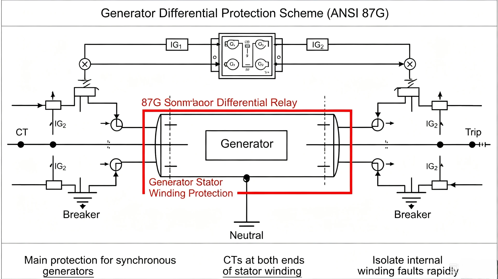
Generator Differential Protection Scheme: Configuration, CT Arrangement and Operation
A generator differential protection scheme is the core zoning and wiring configuration that uses dual-boundary current transformers (CTs) and an 87G differential relay to monitor current balance within a defined generator protection zone. Unlike general protection principles, this engineering-focused scheme defines where protection covers, how CTs are arranged, and when internal or external faults trigger trips. It delivers fast, selective isolation for stator winding faults while maintaining stability during external system disturbances, serving as the primary main protection for all medium and large synchronous generators in power plants.
This article systematically elaborates on practical generator differential protection scheme design, CT installation standards, protection zone division, fault judgment logic, and generator-transformer unit matching schemes. It addresses the core engineering questions searched by EPC contractors, power plant O&M teams, and system protection engineers: how to configure a standard generator differential scheme, where to install zone boundary CTs, how to distinguish internal and external faults, and the key differences between 87G vs 87GT protection configurations.
What Is a Generator Differential Protection Scheme?
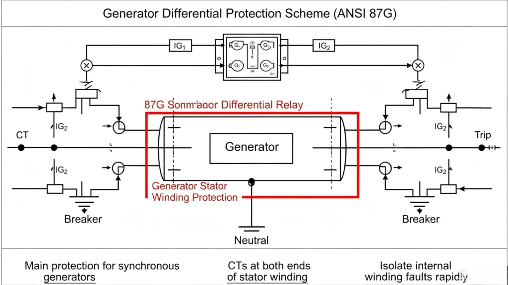
A generator differential protection scheme refers to the complete engineering configuration including CT layout, secondary wiring, relay logic settings, and protection zone partitioning for generator stator differential protection. It is a standardized site implementation solution for 87G generator differential protection, rather than a theoretical working principle.
The core design logic is simple and rigorous: install matched CTs at the two physical boundaries of the generator stator winding. The 87G relay continuously compares the incoming and outgoing current vectors of the protected zone. Balanced current indicates normal operation or external through-faults; unbalanced differential current confirms internal generator faults and triggers trip commands.
Purpose of the Generator Differential Protection Scheme
The scheme is designed for targeted generator safety and power system stability, with four irreplaceable engineering purposes:
- Precise internal fault detection: Accurately identify stator winding phase-to-phase, multi-phase, and partial phase-to-ground faults inside the defined zone
- Ultra-fast fault clearing: Trip within milliseconds to limit stator winding insulation burnout and core overheating damage
- Selective protection restraint: Avoid mal-operation during external bus, transformer, or grid faults to ensure power system continuous operation
- Independent fault isolation: Precisely isolate faulty generators without affecting the operation of other units in the power station
Crucially, the scheme does not respond to overcurrent alone. It judges fault attributes by current imbalance source, which is the fundamental difference between differential protection and conventional overcurrent protection.
What Is 87G Protection?
Defined by ANSI standard protection numbering, 87G stands for Generator Differential Protection. The digit 87 represents the universal differential protection function, while the suffix G specifically denotes generator application scenarios.
The 87G relay is the core control device of the entire differential scheme. It relies on paired zone boundary CT signals to calculate differential current and restraining current, adopting percentage biased logic to balance protection sensitivity and anti-saturation stability. It only executes tripping for faults inside the generator protection zone and restrains action for all external through-faults.
Basic Generator Differential Protection Scheme Diagram & Core Components
A standard generator-only differential protection scheme consists of two sets of boundary CTs, secondary wiring loops, and an 87G protection relay. The closed protection zone covers the entire generator stator winding, which is the most mainstream configuration for independent generator units.
Main Components of 87G Differential Scheme
| Component | Core Engineering Function |
|---|---|
| Generator Terminal CTs | Measure three-phase output current at the generator outlet, forming the external boundary of the protection zone |
| Generator Neutral-Side CTs | Measure three-phase current at the generator neutral end, forming the internal boundary of the protection zone |
| 87G Differential Relay | Collect dual-side CT signals, calculate differential/restraining current, judge fault attributes, and output trip/alarm signals |
| Generator Breaker | Execute physical disconnection commands to isolate faulty generator units |
| Trip Circuit | Transmit relay logic signals to the breaker operating mechanism to complete fault isolation |
How Is the Generator Differential Protection Zone Defined?
In generator differential protection engineering,the CT physical installation position directly determines the protection zone boundary. This is the primary principle for all scheme design and cannot be changed by relay settings.
CT Location Boundary Logic
The standard 87G protection zone is enclosed between neutral-side CTs and terminal-side CTs. All electrical equipment and conductors between the two groups of CTs belong to the protected range, while equipment outside the CT boundaries is excluded from 87G protection.
Equipment Inside the 87G Protection Zone
- Full-range generator stator three-phase windings
- Internal connecting conductors inside the generator casing
- Short-distance busbars between stator winding outlets and terminal CTs
Equipment Outside the 87G Protection Zone
- Generator outlet breaker and external station busbars
- Step-up transformer body and transformer high-voltage side equipment
- Grid transmission lines and external power system equipment
Engineering key point: All faults outside the 87G zone must be restrained by the differential scheme. Tripping for external faults indicates abnormal scheme configuration, CT mismatch, or saturation failure.
Generator Differential Protection CT Arrangement Engineering Standards
CT configuration is the foundation of reliable 87G scheme operation. Unmatched CT parameters, wrong polarity, or unreasonable installation positions are the main causes of differential protection mal-operation and refusal to operate in actual projects.
Generator Terminal CTs Configuration
Terminal CTs are installed at the generator outlet, close to the generator terminal busbar. They are responsible for collecting the total output current of the unit. The CT rated current ratio is matched according to the generator rated stator current, with a reserved 10%–20% overload margin to adapt to long-term light overload operation of the generator.
Terminal CTs require high saturation resistance to ensure accurate current sampling under external short-circuit high current conditions.
Generator Neutral-Side CTs Configuration
Neutral-side CTs are installed on the three-phase branch of the generator neutral point, collecting the reflux current of the stator winding. The model, ratio, and accuracy level must be completely consistent with terminal CTs to ensure current balance under normal operating conditions.
CT Polarity Requirements
CT polarity must strictly match the 87G relay differential logic. Standard engineering wiring ensures that the current vectors input to the relay from terminal and neutral CTs are opposite under normal operation, with zero theoretical differential current.
Reverse polarity will produce persistent false differential current, leading to protection frequent mal-operation; inconsistent polarity of three-phase CTs will cause unbalanced current and failure of normal scheme operation.
CT Ratio and Matching Rules
Dual-side CTs of the 87G scheme must adopt equal ratio and equal accuracy level configuration. The relay performs fine current compensation through internal algorithms to eliminate tiny current errors caused by manufacturing differences of CTs.
Mismatched CT ratios will cause continuous residual differential current, forcing the protection threshold to be increased and reducing the sensitivity of internal fault detection.
How Does the Generator Differential Protection Scheme Operate?
The 87G scheme forms three stable operating states according to different operating conditions, realizing accurate distinction between normal operation, internal faults, and external faults.
Normal Generator Operation State
The current entering the protection zone is equal to the current leaving the zone. The differential current calculated by the 87G relay is close to zero, lower than the protection pickup threshold. The relay keeps restrained state, and no trip signal is output.
Internal Generator Fault State
When a stator winding short-circuit fault occurs inside the CT boundary zone, part of the fault current does not pass through the dual-side CTs, breaking the current balance. The differential current rises sharply and exceeds the setting threshold. After short-time delay confirmation, the 87G relay outputs a trip signal to cut off the generator breaker.
External System Fault State
External busbar or grid short-circuit will generate high through-fault current passing through the generator zone. The current values of dual-side CTs remain basically balanced. The 87G relay relies on restraining current to suppress false differential current and keeps stable restrained state without mal-operation.
Applicable Faults of Generator Differential Protection Scheme
The 87G differential scheme is the primary protection for generator stator faults, with clear applicable fault types and detection limitations, which is critical for engineering protection configuration.
Phase-to-Phase Faults
All stator winding phase-to-phase short-circuit faults inside the zone can generate obvious differential current, with high detection sensitivity and reliable trip action. This is the most typical applicable fault of 87G protection.
Phase-to-Ground Faults
The detection capability of single-phase ground faults depends on the generator neutral grounding mode. For low-current grounding systems with small fault current, the 87G scheme has limited sensitivity for slight ground faults and needs to cooperate with 64G stator ground fault protection.
Multi-Phase Stator Faults
Two-phase and three-phase short-circuit faults have large fault current and significant current imbalance. The 87G scheme can reliably detect and trip, effectively avoiding severe burnout of stator windings and iron cores.
Inter-Turn Faults
Traditional terminal-neutral differential schemes have limited detection ability for minor inter-turn faults of stator windings. Because the current imbalance caused by partial turn-to-turn short circuit is small, it may not reach the differential pickup threshold. For units with high winding safety requirements, auxiliary inter-turn fault protection needs to be configured additionally.
Scheme Performance During External Faults & CT Saturation Handling
External through-faults and CT saturation are the main challenges affecting the stability of 87G differential schemes, and percentage biased differential logic is the core solution in engineering.
Through-Fault Current Characteristics
External short-circuit faults will produce several times of rated current passing through the generator, but this high current is a balanced through-current inside the protection zone. High current value alone is not a fault criterion for differential protection.
CT Saturation Risk
Under ultra-large external fault current, CTs are prone to saturation, resulting in distorted secondary current. If the saturation degree of terminal and neutral CTs is inconsistent, false differential current will be generated, which may cause protection mal-operation.
Percentage-Biased Differential Protection Logic
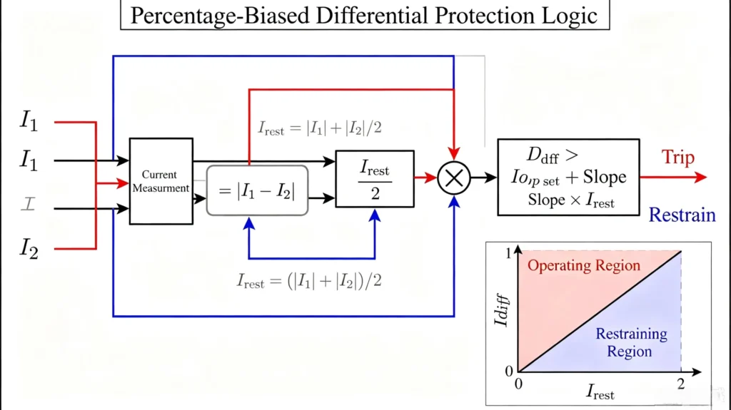
The 87G relay adopts the industry-standard biased differential algorithm:
Idiff = |I1 – I2|, Irest = (|I1| + |I2|) / 2
The relay dynamically improves the differential threshold according to the increase of restraining current. It maintains high sensitivity for small internal fault current and improves anti-interference ability for large external through-current, realizing the dual goals of internal fault sensitivity and external fault stability.
Generator Differential Scheme for Generator-Transformer Units
For grid-connected units with generator-step-up transformer integrated configuration, the protection scheme needs to be adjusted according to CT boundary positions, forming two typical configuration modes, and clarifying the application difference between 87G vs 87GT.
Generator-Only Differential Scheme (Pure 87G)
CTs are arranged on the generator neutral side and terminal side. The protection zone only covers the generator stator, excluding transformers and external equipment. It is applicable to independent generator units with separate outlet breakers.
Generator-Transformer Unit Differential Scheme (87GT)
For unit-connected generators without intermediate breakers, the differential protection zone is expanded to the transformer side. The 87GT relay adopts matched CTs at the generator neutral end and transformer high-voltage end, covering the generator and step-up transformer as a whole.
87G vs 87GT Core Engineering Comparison
| Comparison Item | 87G Generator Differential | 87GT Generator-Transformer Differential |
|---|---|---|
| Protected Equipment | Independent generator stator winding | Generator + step-up transformer integrated zone |
| CT Boundary Range | Generator neutral & terminal CTs | Generator neutral CT & transformer high-side CT |
| Transformer Fault Coverage | Not included | Fully included in the protection zone |
| Compensation Requirements | Only generator CT ratio matching | Need transformer ratio & phase shift compensation |
| Applicable Scenario | Generator with independent outlet breaker | Integrated generator-transformer unit connection |
Note: The definition of 87GT protection varies slightly by relay manufacturer. The final protection zone must be verified according to project single-line diagrams and relay official manuals.
Field Wiring & Connection Specifications
Secondary wiring is the key link to ensure the effective operation of the 87G scheme. Standardized construction avoids most on-site protection faults.
CT Secondary Connection Rules
All CT secondary circuits adopt closed wiring, no open circuit operation. The secondary wiring is directly connected to the 87G relay current input terminal, with short transmission distance and minimal loop impedance to reduce signal attenuation.
Phase Sequence Matching
The three-phase A/B/C sequence of terminal and neutral CTs must correspond one-to-one. Cross-phase wiring will cause complete disorder of differential current calculation and failure of protection logic.
Secondary Grounding & Polarity Verification
CT secondary circuits implement single-point grounding specifications to prevent induced overvoltage damage to the relay. Polarity tests must be completed before commissioning to confirm the consistency of dual-side current vectors.
Relay Input Configuration
Set CT ratio, phase sequence, differential logic parameters, and compensation coefficients according to actual field parameters to match the on-site protection scheme.
Key Design Considerations for 87G Protection Scheme
The following checklist covers all core factors of scheme design, applicable to new power plant construction and old unit protection renovation projects:
- Generator rated parameters: Match CT ratio and protection threshold according to generator MVA rating, rated voltage, and stator current
- Neutral grounding mode: Determine ground fault detection capability and matching auxiliary protection schemes
- CT technical parameters: Select accurate level and high saturation-resistant CTs, verify load capacity and ratio matching
- CT installation position: Confirm boundary range to avoid unreasonable protection zone deviation
- Grid connection configuration: Select 87G independent scheme or 87GT unit scheme according to breaker and transformer layout
- Coordinated protection functions: Match with 50/51 overcurrent, 64G ground fault, 46 unbalanced current, and 40 loss-of-excitation protection
87G Scheme vs Other Generator Protection Functions
| ANSI Code | Protection Function | Core Purpose |
|---|---|---|
| 87G | Generator Differential Protection | Primary protection for internal stator short-circuit faults |
| 50/51 | Overcurrent Protection | Backup protection for internal and external faults |
| 64G | Stator Ground Fault Protection | Detect generator single-phase ground faults |
| 46 | Negative Sequence Protection | Protect against unbalanced load and asymmetric faults |
| 40 | Loss of Excitation Protection | Prevent generator out-of-step operation |
| 32 | Reverse Power Protection | Prevent motor operation of generator |
Key conclusion: 87G differential protection is the fastest and most reliable primary protection for generator internal faults, but it cannot replace other protection functions. A complete generator protection system requires coordinated configuration of multiple protection schemes.
Practical Engineering Application Case
Project Background: 10MW synchronous generator unit, equipped with independent outlet breaker, neutral ungrounded system, matched with standalone 87G differential protection scheme.
Scheme Implementation Steps:
- Confirm protection zone: Define zone boundary via generator neutral and terminal dual-side CTs, covering all stator windings
- Select CT parameters: Match CT ratio according to generator rated stator current, select 0.2S high-precision saturation-resistant CTs
- Relay configuration: Complete CT ratio input, phase sequence calibration, and biased differential parameter setting on 87G relay
- Internal fault verification: Stator phase-to-phase short-circuit test generates obvious differential current, relay trips accurately
- External fault verification: Busbar short-circuit through-fault occurs, CT current remains balanced, protection keeps stable without mal-operation
Common On-Site Faults & Troubleshooting
- Incorrect CT polarity: Cause residual differential current, frequent false alarm; solution: re-calibrate secondary wiring polarity
- CT ratio mismatch: Lead to persistent current imbalance; solution: replace matched CTs or enable relay ratio compensation
- Wrong phase sequence: Destroy differential current balance logic; solution: adjust three-phase wiring correspondence
- External fault CT saturation: Generate false differential current; solution: optimize biased threshold and adopt high-saturation CTs
- Incorrect zone definition: Cause missing protection or over-protection; solution: reconfirm CT installation position and single-line diagram
Scheme Commissioning Testing Scope
On-site commissioning of generator differential protection scheme focuses on functional verification rather than principle testing. The core test items include CT polarity check, ratio verification, phase sequence calibration, secondary loop integrity test, differential current simulation, external through-fault stability test, and trip loop action verification. All test data provides reliable basis for formal grid-connected operation of the unit.
Key Takeaways
A standard generator differential protection scheme relies on dual-boundary CT configuration and an 87G relay to form a fixed generator protection zone. CT physical positions determine the protection coverage range, which is the core of scheme design. Internal stator faults create unbalanced differential current to trigger tripping, while external through-faults maintain current balance to ensure protection stability.
CT ratio matching, polarity correctness, phase sequence standardization, and reasonable relay parameter configuration are the four key factors to ensure long-term reliable operation of the scheme. For generator-transformer integrated units, engineers need to select 87G or 87GT schemes according to actual equipment layout to avoid protection zone mismatch.
FAQs
1. What is a generator differential protection scheme?
It is a complete engineering protection configuration composed of boundary CTs, secondary wiring, and 87G relay, used to monitor current balance in the generator zone and realize selective trip for internal stator faults.
2. How does a generator differential protection scheme work?
The 87G relay compares the inlet and outlet current of the generator protection zone. Internal faults produce differential current to trigger tripping; normal operation and external faults keep current balance to restrain protection action.
3. Where are CTs installed in generator differential protection?
CTs are installed at the generator neutral side and terminal side respectively, forming the physical boundary of the differential protection zone.
4. What is the protection zone of 87G?
The 87G protection zone covers all generator stator windings and internal conductors between neutral-side and terminal-side CTs, excluding external breakers, busbars and transformers.
5. What faults can generator differential protection detect?
It reliably detects stator phase-to-phase, multi-phase short-circuit faults and most severe ground faults, with limited sensitivity for minor inter-turn and high-resistance ground faults.
6. Why does 87G not trip for external faults?
External faults only generate balanced through-fault current, with no effective differential current in the protection zone. The biased differential logic further ensures protection stability.
7. What is the difference between 87G and 87GT?
87G is dedicated to independent generator protection, while 87GT is applied to generator-transformer integrated units with a wider protection zone covering transformers.
8. What CT parameters are required for 87G relay configuration?
It requires CT ratio, accuracy class, saturation performance, phase sequence, and polarity parameters to complete relay matching configuration.
Relay Selection Guidance for Engineering Projects
The selection of generator differential protection relay must be matched with actual project conditions, including generator rated capacity, CT configuration parameters, neutral grounding mode, grid connection scheme, and coordinated protection requirements. For new construction and renovation projects, providing generator single-line diagrams and CT parameter sheets can realize accurate scheme matching and relay configuration optimization, ensuring the safety and stability of generator long-term operation.
Reference Technical Documents & Data Sources
- IEEE C37.102-2019: Guide for AC Generator Protection
- ANSI/IEEE C37.2-2008: Standard Electrical Power System Device Function Numbers
- IEC 60034-1: Rotating electrical machines – Rating and performance
- IEC 61850-7-4: Communication networks and systems for power utility automation
- Manufacturer official technical manuals for 87G/87GT differential protection relays
- Power Plant Relay Protection Engineering Design Specification (Industry Standard)



About Author

Hello, I'm Leno Zhang. I have 15 years of experience in the power relay protection industry with extensive pre-sales and after-sales project experience. Our company specializes in various complete sets of relay protection and automation equipment. I can assist customers in solving all practical on-site project challenges and provide optimal integrated solutions.
Tell Us Your Requirement
High Quality
Stable performance, reliable design, ensuring safe operation for power system protection and grid stability.
Fast Delivery
Timely delivery to support your urgent orders and project schedules efficiently and professionally at any time.
Best Warranty
Professional Warranty: Reliable after-sales support for stable relay protection and long-term customer satisfaction.