

-
Leon Zhang sales consultant
-
Email: zxl635973785@gmail.com
-
Phone/WhatsApp: +86 13655813266
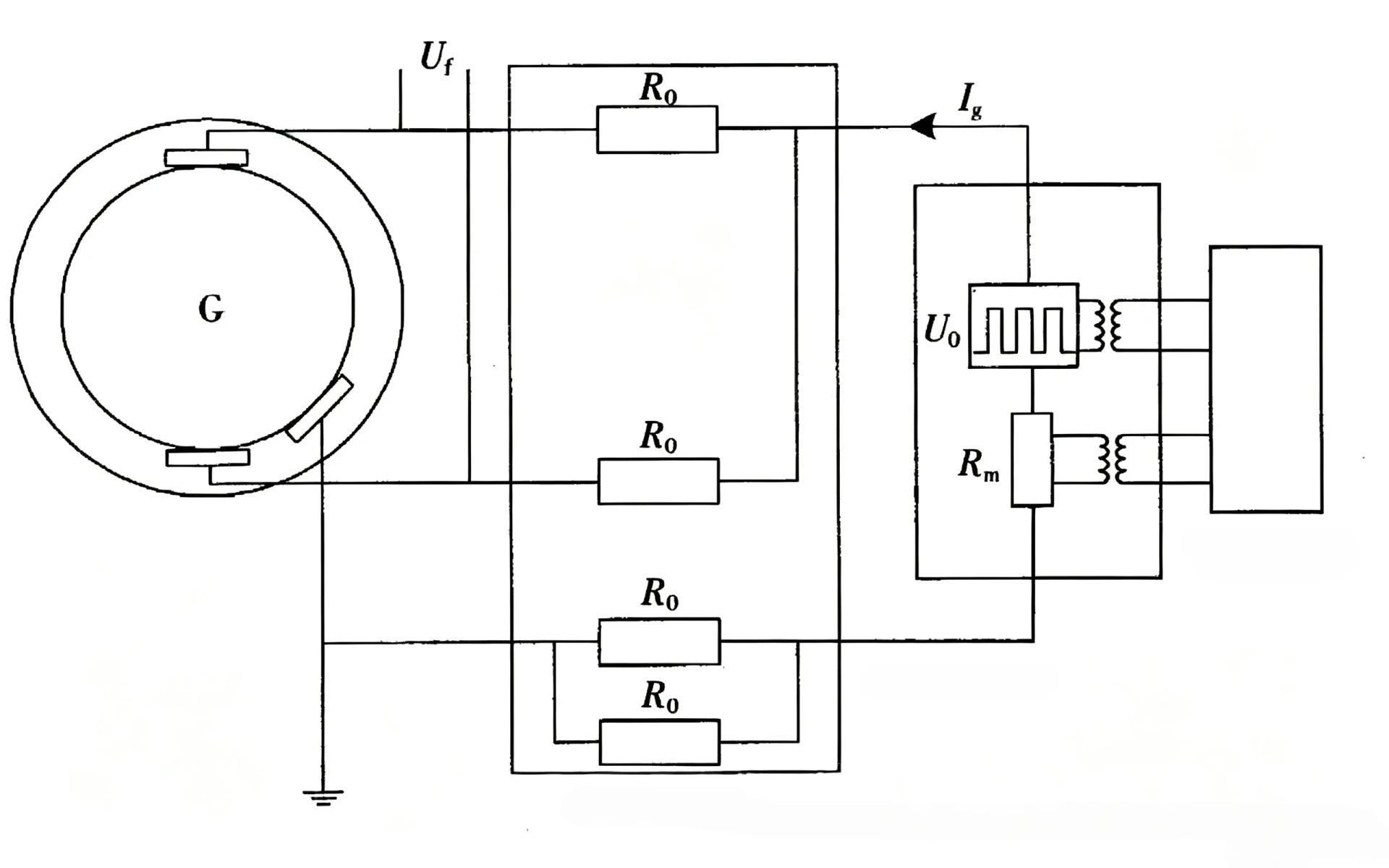
Voltage Injection Rotor Earth Fault Protection: Working Principle and Applications
Quick Answer
Voltage injection rotor earth fault protection detects insulation faults between a synchronous generator’s rotor field winding and ground by applying a controlled test voltage to the rotor circuit and measuring the resulting electrical response. When the measured rotor-to-ground insulation condition falls below the configured protection threshold, the 64R relay can issue an alarm or trip signal. The method enables continuous online monitoring and is commonly applied to large synchronous generators, including hydroelectric and turbo-generators.
Introduction
Large synchronous generators rely on electrically isolated rotor field windings to maintain stable excitation and magnetic field balance during operation. Under normal operating conditions, the rotor circuit is fully ungrounded, with no conductive path between the field winding and the generator ground reference.
Single‑point rotor earth faults seldom produce large fault currents, making conventional overcurrent protection ineffective. Yet such insulation failure permanently degrades rotor insulation margin, significantly raising risks of a second earth fault elsewhere in the rotor winding.
Two‑point rotor earth faults short‑circuit part of the field winding, causing distorted magnetic fields, excessive rotor vibration, local winding overheating, rotor‑shaft mechanical stress, forced generator tripping or permanent equipment damage. Hence, continuous on‑line rotor insulation monitoring is standard for medium‑to‑large synchronous generators globally.
As a mature and reliable 64R protection implementation, voltage injection rotor earth fault protection provides real-time insulation condition monitoring by injecting a controllable test signal into the rotor circuit.
By reading this guide, professionals will fully understand: what voltage injection rotor earth fault protection is, how it detects single and double rotor ground faults, its differences from Ping-Pong detection schemes, and key points for field deployment and relay selection.
What Is Voltage Injection Rotor Earth Fault Protection?
Definition: Voltage injection rotor earth fault protection is a standardized generator 64R protection method that applies low-level controllable AC, low-frequency AC, or customized test voltage to the generator rotor field circuit. The protection relay analyzes leakage current, phase deviation, and rotor-to-ground impedance changes to identify insulation degradation and rotor earth faults, and triggers alarm or trip actions based on preset thresholds.
Unlike passive protection schemes that rely on fault-generated electrical signals, this active injection method realizes continuous online monitoring regardless of generator load status, which solves the blind spot of traditional rotor protection in light-load or no-load operating conditions.
Core Objects of Voltage Injection Protection
To clarify the working boundary of the protection scheme, it is necessary to define the core monitored circuit components:
- Rotor field winding: The excitation winding mounted on the generator rotor, responsible for generating the main magnetic field; the core monitoring object of 64R protection.
- Rotor circuit: A closed circuit composed of field winding, excitation output loop, rotor shaft, and insulation medium, operating in an ungrounded state during normal operation.
- Insulation medium: Insulating materials between rotor winding, shaft, and stator core, which determines the rotor-to-ground insulation resistance value.
- Ground reference point: The generator’s unified system ground, serving as the return path for the injection test signal.
What Does “Voltage Injection” Mean?
Voltage injection refers to the active injection of a stable, low-amplitude test voltage signal into the floating rotor ungrounded circuit. The complete signal transmission path is fixed and standardized:
Injection Unit → Rotor Field Winding → Insulation Medium → Ground Reference Point → Detection Circuit → Protection Relay Measurement Unit
The injected test signal builds a stable measurable electrical loop. When the rotor insulation is intact, the loop only generates tiny leakage current; when insulation aging, damage, or ground faults occur, the loop impedance drops sharply, and the leakage current increases significantly, providing quantifiable fault data for the relay.
Core Monitored Parameters and Purposes
The protection system judges the rotor insulation status through multi-dimensional parameter fusion, avoiding misjudgment caused by single data deviation:
| Monitored Parameter | Core Purpose |
|---|---|
| Injected test voltage | Provides stable standardized detection signal, ensures measurement consistency |
| Injection return current | Reflects leakage path changes, directly indicates insulation abnormality |
| Rotor-to-ground impedance | Quantifies insulation aging degree and fault severity |
| Fault resistance value | Distinguishes slight insulation degradation and hard ground faults |
| Alarm/trip status | Outputs protection actions to avoid secondary generator damage |
Why Is Rotor Earth Fault Protection Necessary?
Most generator mechanical and electrical failures caused by rotor grounding are progressive. Timely 64R protection monitoring is the key to eliminating hidden dangers in advance and avoiding major shutdown losses.
Rotor Circuit Is Naturally Ungrounded
The generator rotor excitation circuit adopts a floating ungrounded design to prevent grounding circulation and ensure stable excitation output. This structural feature makes the rotor circuit lack a fixed ground reference, so traditional current-based protection cannot capture weak fault signals.
Single Ground Fault Produces No Obvious Fault Current
A single-point rotor earth fault only forms a single conductive connection between the winding and the ground, with no closed short-circuit loop. The fault current is extremely small, which cannot trigger conventional overcurrent or overvoltage protection. The generator can still operate normally on the surface, resulting in long-term hidden faults.
Secondary Ground Fault Causes Irreversible Damage
After the first ground fault occurs, the local insulation performance of the rotor is completely destroyed, and the overall insulation margin is greatly reduced. Under the impact of unit vibration, temperature rise, and electromagnetic force during long-term operation, a second ground fault is highly likely to occur at another position of the winding.
Two-point grounding will short-circuit part of the rotor field winding, causing asymmetric magnetic field distribution. The direct consequences include rotor unbalanced vibration, local overheating of the winding, insulation burnout, excitation system instability, and even rotor shaft magnetization, which will force the unit to shut down and bring huge economic losses to the power plant.
Working Principle of Voltage Injection Rotor Earth Fault Protection
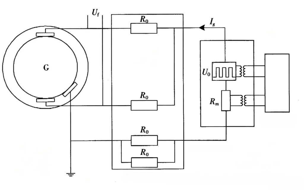
The core logic of voltage injection protection is active signal injection → loop response acquisition → insulation parameter calculation → threshold comparison and action. The complete working process is divided into five standardized steps, applicable to all mainstream digital 64R relays.
Step 1: Generate Standardized Injection Signal
The relay’s internal injection module generates a stable low-amplitude test signal. According to different product designs and excitation system matching requirements, the signal types include conventional AC, low-frequency AC, and optimized DC composite signals. The injection voltage amplitude and frequency are fixed and controllable, avoiding interference with the generator’s normal excitation signal. The specific parameters are determined by the relay model and unit operating conditions.
Step 2: Couple Signal into Rotor Circuit
The test signal is coupled to the generator rotor excitation loop through an isolation coupling circuit. The signal covers the entire field winding, insulation medium, and rotor shaft system, forming a complete detection loop with the system ground.
Step 3: Monitor Return Leakage Response
In healthy operating conditions, the rotor insulation resistance is high, and only microampere-level tiny leakage current exists in the loop, with stable phase and amplitude. When insulation aging or grounding occurs, the loop impedance decreases, and the leakage current increases significantly, with obvious phase deviation.
Step 4: Calculate Rotor-to-Ground Insulation Status
The relay calculates the real-time insulation resistance based on the basic formula R≈V/I. Different from simple manual calculation, industrial digital relays adopt multi-algorithm fusion processing, combining signal filtering, amplitude calibration, phase compensation, and interference suppression algorithms to eliminate the influence of generator operating noise and ensure measurement accuracy.
Step 5: Compare with Protection Thresholds and Execute Actions
The system compares the calculated insulation resistance and fault parameters with factory and user-set thresholds:
- Normal status: Insulation resistance is higher than the warning threshold, the system continues real-time monitoring without outputting any signal.
- Early insulation deterioration: Parameters reach the warning threshold, the relay outputs an alarm signal to remind maintenance personnel of inspection.
- Serious fault: Parameters reach the trip threshold, the relay executes trip logic to protect the generator equipment.
How Does a 64R Relay Detect Rotor Earth Faults?
Definition of ANSI 64R Protection
In accordance with ANSI/IEEE standard device numbering rules, 64R refers exclusively to Rotor Earth Fault Protection, which is dedicated to monitoring insulation faults of generator rotor field windings. It is one of the mandatory protection configurations for large and medium-sized synchronous generators, independent of stator grounding protection (64S).
64R Protection Core Logic Flow
The complete working logic of the voltage injection-based 64R relay is standardized and repeatable:
Rotor circuit normal operation → Inject fixed test signal → Collect loop leakage response → Calculate real-time insulation resistance → Compare with preset thresholds → Output alarm/trip/continue monitoring
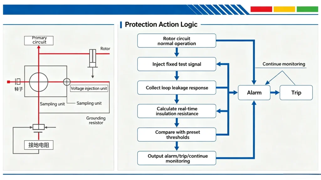
Classification of Voltage Injection Detection Methods
According to different injection signal types and technical principles, mainstream voltage injection rotor earth fault protection is divided into three categories, with different application scenarios and technical advantages.
Conventional AC Voltage Injection
This scheme injects standard power-frequency AC signals, with simple circuit design and stable operation. It supports full-cycle online continuous monitoring, suitable for most conventional turbo-generators and hydro-generators. It is the most widely used 64R protection scheme in traditional power plants.
Low-Frequency AC Injection
Low-frequency signals are adopted to avoid frequency superposition and electromagnetic interference with the generator’s excitation frequency and power frequency signals. This scheme features higher measurement stability and lower false alarm rate, suitable for units with complex excitation systems and high electromagnetic interference on site.
DC Composite Injection
DC-based composite test signals are used for insulation measurement, which can effectively filter AC interference signals. It has high accuracy for low-resistance fault detection and is mostly used for high-precision insulation monitoring of large-capacity hydro-generators.
Essential Concept Distinction
Voltage injection is a general measurement technical method, while rotor earth fault protection (64R) is a specific protection function. All mainstream online 64R protection relays are developed based on voltage injection principles in essence.
Protection Status Under Different Rotor Fault Conditions
The voltage injection scheme can accurately identify healthy status, insulation aging, single-point grounding, and two-point grounding faults. The corresponding measurement responses and protection actions are standardized as follows:
| Rotor Operating Condition | Insulation Characteristic | Measurement Response | Protection Status |
|---|---|---|---|
| Healthy rotor | High and stable rotor-to-ground resistance | Tiny stable leakage current, no abnormal fluctuation | Normal continuous monitoring |
| Early insulation degradation | Gradually reduced insulation resistance | Slowly increased leakage current | Early warning prompt |
| Single-point rotor earth fault | Low-resistance fixed grounding path formed | Significant increase in leakage current, obvious impedance drop | Alarm output, risk reminder |
| Two-point rotor earth fault | Multiple grounding paths, partial winding short circuit | Severe abnormal electrical parameters, drastic data fluctuation | Trip protection action |
Hazards of Single and Double Ground Faults
A single ground fault is a latent fault without immediate hazards but completely destroys the insulation safety margin. Two-point grounding is a destructive fault that directly endangers the safe operation of the unit. Therefore, the core purpose of online monitoring is to capture single-point faults in advance and avoid secondary fault escalation.
Voltage Injection vs Ping-Pong Rotor Earth Fault Protection
Ping-Pong protection is another mainstream rotor earth fault detection scheme in the industry. There is no absolute advantage or disadvantage between the two; they differ greatly in technical positioning and application focus, and can even be compatible in some high-end protection systems.
Overview of Ping-Pong Protection
Ping-Pong rotor earth fault protection realizes fault detection and positioning by periodically switching the circuit measurement configuration. Its core advantage is accurate fault point location, which is convenient for on-site maintenance personnel to quickly find damaged winding positions.
Core Technical Differences
| Comparison Aspect | Voltage Injection Protection | Ping-Pong Protection |
|---|---|---|
| Core Principle | Inject fixed test voltage to monitor insulation parameters | Alternate circuit switching to collect different state responses |
| Main Purpose | Continuous online insulation monitoring and fault early warning | Fault detection and accurate fault location |
| Measurement Basis | Voltage, current, impedance steady-state data | Parameter difference under different circuit states |
| Application Focus | Long-term real-time monitoring of operating units | Post-fault location and maintenance auxiliary |
It is worth noting that the two schemes are not mutually exclusive. Ping-Pong positioning technology can be used as an extended function of voltage injection protection, forming a complete set of “monitoring + positioning” rotor earth fault protection solutions.
Core Components of Voltage Injection Protection System
A complete 64R voltage injection protection system consists of five core modules, with coordinated functions to ensure stable and reliable long-term operation:
1. Injection Module
Generates stable test signals of specified frequency and amplitude, and completes signal isolation and coupling to avoid interference with the excitation system.
2. Measuring Circuit
Collects return voltage, current and phase signals, filters out on-site electromagnetic interference, and transmits effective data to the main control unit.
3. 64R Protection Relay
The core control unit, responsible for data calculation, threshold judgment, alarm/trip output, fault recording and data storage.
4. Isolation and Filtering Components
Including isolation transformers and filter circuits, which improve system anti-interference ability and ensure measurement accuracy in complex power plant environments.
5. Communication and HMI Interface
Supports local parameter display, and remote data transmission through Modbus, IEC standard protocols, realizing remote monitoring and system integration.
Typical Application Scenarios
Voltage injection 64R protection is suitable for all large and medium-sized synchronous generator sets, covering new projects and old equipment renovation scenarios:
- Hydroelectric generators: Long-term continuous operation, high requirements for insulation stability, suitable for 24-hour online monitoring.
- Turbo-generators: Conventional thermal power units, matching with most excitation systems, widely used in traditional power plants.
- New energy supporting generators: Peak-shaving and frequent start-stop units, prone to insulation fatigue, requiring real-time fault monitoring.
- Old power plant renovation projects: Replace obsolete analog relays and discontinued protection equipment, upgrade to digital online monitoring schemes.
Online Protection vs Offline Insulation Testing
On-site operation and maintenance requires a clear distinction between the two detection methods, which are complementary rather than substitutable:
| Comparison Item | Online Voltage Injection Protection | Offline Insulation Test |
|---|---|---|
| Generator Status | Normal grid-connected operation | Shutdown and power-off state |
| Monitoring Mode | 24-hour continuous real-time monitoring | Regular periodic sampling detection |
| Core Purpose | Fault early warning and real-time protection | Maintenance diagnosis and insulation performance evaluation |
| Response Speed | Millisecond-level real-time response | Static test after shutdown, no real-time response |
Offline tests can only detect static insulation status, while online voltage injection protection can capture dynamic insulation changes during unit operation, which is the core guarantee for unit operational safety.
Key Relay Selection Parameters
For EPC engineers and project owners, relay selection should focus on practical matching parameters rather than brand publicity, to avoid on-site incompatibility and detection failure:
- Excitation system compatibility: Match the generator excitation type, field voltage and current range to ensure signal coupling adaptation.
- Injection signal parameters: Select AC/low-frequency/DC injection mode according to on-site electromagnetic interference intensity.
- Measurement range and accuracy: Cover the full range of rotor insulation resistance changes, with high precision for low-resistance fault identification.
- Protection response time: Meet power plant protection standard response speed, avoid fault delay and expansion.
- Communication compatibility: Support mainstream industrial protocols, convenient for docking with DCS and SCADA systems.
- Anti-interference performance: Adapt to high-temperature, high-vibration and strong electromagnetic interference environment of power plants.
Field Installation and Commissioning Specifications
Standardized commissioning is the key to ensure the reliable operation of 64R protection. The recommended on-site commissioning sequence is universal and applicable to all voltage injection relays:
Technical document review → Rotor field circuit inspection → Wiring polarity verification → Pre-energization insulation test → Relay parameter setting → Injection signal verification → Artificial earth fault simulation → Alarm function test → Trip output test → Final acceptance and commissioning
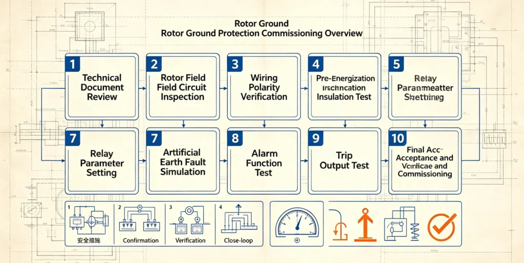
Key commissioning points: Strictly verify the integrity of the injection loop, avoid wrong wiring leading to false alarms or missing detection; simulate multiple fault resistance values to calibrate threshold accuracy; confirm that communication and remote transmission functions are normal.
Common On-Site Faults and Troubleshooting
1. False earth fault alarm
Main causes: On-site electromagnetic interference, unstable wiring contact, abnormal coupling circuit, and parameter threshold setting unreasonably. Solutions: Optimize wiring shielding, check loop connectivity, recalibrate signal parameters, and adjust filtering coefficients.
2. Failed to detect actual ground fault
Main causes: Blocked injection loop, incorrect threshold setting, mismatched excitation system, and damaged measuring components. Solutions: Inspect the full link of the detection loop, reset protection parameters, and verify system compatibility.
3. Unstable insulation resistance data
Main causes: Excessive on-site interference, poor grounding, and unreasonable signal filtering. Solutions: Optimize system grounding and enhance signal filtering processing.
Advantages and Limitations
Core Advantages
- Realize 24-hour online continuous monitoring without shutting down the unit.
- Effectively capture early insulation degradation and single-point latent faults.
- Stable measurement, low false alarm rate, strong on-site adaptability.
- Support alarm and trip dual protection functions to avoid equipment damage.
- Easy to integrate with digital power plant systems, suitable for new construction and renovation projects.
Technical Limitations
- Need to match the generator excitation system, poor compatibility with individual special excitation modes.
- Installation and commissioning require standardized operation, irregular wiring will affect measurement accuracy.
- Long-term operation requires regular parameter calibration to ensure detection stability.
Engineering Application Case
Project Background
A 50MW hydroelectric generator in Southeast Asia has been in operation for 12 years. The original old analog rotor protection device has aging functions, no online monitoring capability, and can only rely on regular offline maintenance tests, with major operational safety hazards. The owner needs to upgrade to a digital 64R voltage injection protection scheme to realize real-time insulation monitoring.
Protection Requirements
Realize continuous online monitoring of rotor insulation, support single-point fault alarm and serious fault trip, compatible with the original excitation system, and dock with the existing power plant SCADA system.
Implementation Scheme
Adopt low-frequency AC voltage injection 64R relay, complete loop transformation and signal coupling, set reasonable alarm and trip thresholds, and configure remote communication functions.
Operation Effect
After the transformation, the system operates stably, realizes real-time perception of rotor insulation status, successfully captures multiple times of slight insulation degradation, and reminds the maintenance team to handle it in advance. No rotor grounding fault escalation accident has occurred since the operation, effectively ensuring the safe and stable operation of the unit.
FAQ
1. What is voltage injection rotor earth fault protection?
It is a mainstream 64R generator protection method that injects controllable test voltage into the rotor circuit, judges insulation status through leakage current and impedance changes, and realizes online monitoring and fault protection of rotor earth faults.
2. How does a voltage injection rotor earth fault relay work?
The relay actively injects test signals, collects loop electrical response data, calculates rotor-to-ground insulation parameters, and outputs alarm or trip actions by comparing with preset thresholds.
3. What is ANSI 64R protection?
ANSI 64R is the standard device number for generator rotor earth fault protection, specially used for monitoring rotor winding insulation faults, which is an essential protection for large synchronous generators.
4. Why do synchronous generators need rotor earth fault protection?
Single rotor ground faults are latent and undetectable by conventional protection, while secondary grounding will cause serious mechanical and thermal damage to the unit. Continuous 64R monitoring can effectively avoid major equipment accidents.
5. Can voltage injection scheme detect single-point rotor earth fault?
Yes, it can accurately identify single-point grounding and early insulation degradation, and issue alarm prompts to prevent fault escalation.
6. What is the difference between voltage injection and Ping-Pong protection?
Voltage injection focuses on long-term continuous online monitoring and early warning, while Ping-Pong technology is more inclined to post-fault accurate positioning. The two can be compatible and complementary.
7. Can the protection operate during generator grid-connected operation?
Yes, it supports full-load, light-load and no-load online monitoring, without affecting the normal operation of the generator and excitation system.
8. What are the core parameters for 64R relay selection?
Excitation system compatibility, injection signal mode, measurement accuracy, response time, communication protocol and on-site environmental adaptability.
Conclusion
Voltage injection rotor earth fault protection is a mature, reliable and widely applicable 64R protection implementation scheme for synchronous generators. Different from traditional passive protection and offline detection, its active injection and continuous online monitoring capability make up for the blind spot of rotor latent fault detection, and can effectively prevent equipment damage caused by two-point rotor grounding.
The core value of the Voltage Injection Rotor Earth Fault Protection Relay scheme is insulation monitoring, early fault alarming and safe‑operation protection. Proper relay selection, standard installation and rational parameter setting are critical to optimal protection performance. It is a cost‑effective, high‑reliability technical option for new power‑plant projects and legacy‑equipment retrofits.
Reference Technical Documents & Data Sources
- IEEE C37.102-2018, Guide for Generator Protection
- ANSI/IEEE Standard Device Numbers for Power System Protection Relays
- GB/T 14285-2020, Technical Code for Relay Protection of Power Equipment
- IEC 60034-1:2017, Rotating electrical machines – Part 1: Rating and performance
- Power Plant Generator Excitation System Operation and Maintenance Technical Manual
- Industrial Digital Protection Relay General Technical Specification



About Author

Hello, I'm Leno Zhang. I have 15 years of experience in the power relay protection industry with extensive pre-sales and after-sales project experience. Our company specializes in various complete sets of relay protection and automation equipment. I can assist customers in solving all practical on-site project challenges and provide optimal integrated solutions.
Tell Us Your Requirement
High Quality
Stable performance, reliable design, ensuring safe operation for power system protection and grid stability.
Fast Delivery
Timely delivery to support your urgent orders and project schedules efficiently and professionally at any time.
Best Warranty
Professional Warranty: Reliable after-sales support for stable relay protection and long-term customer satisfaction.