

-
Leon Zhang sales consultant
-
Email: zxl635973785@gmail.com
-
Phone/WhatsApp: +86 13655813266
Motor Protection Relay Manufacturer for Industrial and Power Applications
Motor Protection Relay Manufacturing Capabilities
As a professional Motor Protection Relay Manufacturer, we maintain complete vertical integration from R&D to factory acceptance. Our core manufacturing capabilities include:
Product Development & System Architecture
We define product specifications in-house and develop modular hardware platforms supporting flexible I/O configurations, multiple communication protocols (Modbus, Profibus, IEC 61850), and scalable protection functions for both LV and MV motor applications.
Hardware Design & PCB Engineering
In-house design covers precision analog sensing circuits, high-speed digital signal processing, isolated power supplies, output drivers, and EMC-compliant PCB layout. Rated for -40°C to +85°C industrial environments, verified against surge, burst, and ESD immunity.
Protection Algorithm Development
Proprietary algorithms include thermal overload, phase loss/reversal/unbalance, earth fault, short-circuit/locked rotor, over/under voltage, over/under frequency, and starting supervision. Validated against actual motor waveforms and field data for reliable operation with minimum nuisance tripping.
Embedded Software & Firmware
Deterministic real-time control code delivers <20ms fault response, non-volatile parameter storage, multi-protocol communication, local HMI interaction, time-stamped event logging, and remote firmware upgrade capability.
Assembly & Manufacturing
ESD-safe workstations covering SMT placement, through-hole soldering, CT/PT termination, IP54/IP65 enclosure sealing, and torque-controlled terminal connections. Full barcode traceability with standardized operating procedures.
Functional Testing
100% automated testing simulating motor start, running, and fault conditions. Verifies protection accuracy (±2%), time delay curves, I/O response, communication, and contact performance. All test results electronically stored.
Calibration & Precision Adjustment
Two-stage calibration using traceable 0.05-grade reference sources: gain/offset trimming, system calibration, and temperature compensation. Each unit ships with its own calibration certificate.
Quality Inspection
Covers incoming, in-process, and outgoing inspections, plus batch environmental sampling (thermal cycling/humidity). ISO 9001-compliant with layered process audits conducted regularly.
Factory Acceptance Testing (FAT)
Witnessed testing per customer requirements, including protection function demonstration, communication handshake, trip circuit verification, and visual inspection. Signed FAT report issued to ensure plug-and-play readiness upon delivery.
Traceability & Continuous Improvement
Each relay is assigned a unique serial number linking to batch codes, assembly records, test/calibration data, and firmware version. Field feedback and production metrics (yield rate, defect analysis) drive ongoing improvements.
Types of Motor Protection Relay
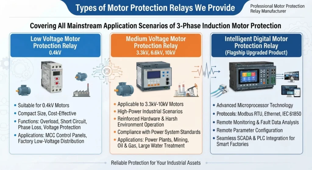
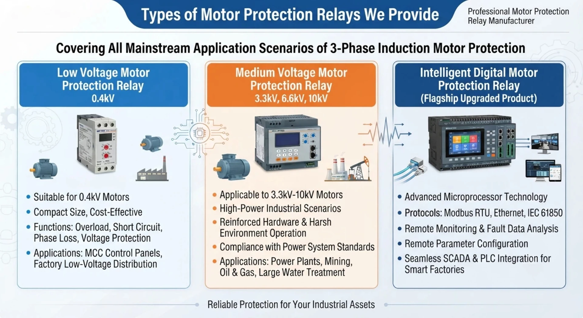
Our product portfolio covers four major series: Motor Differential Protection, Motor Comprehensive Protection, Self-Balancing Differential Protection , and Low Voltage Motor Protection — providing complete solutions for motor protection across low voltage to medium/high voltage applications, from simple to complex requirements.
Motor Differential Protection Relay
Employing percentage biased differential protection principle, designed specifically as the primary protection for winding internal faults in large and medium-sized high-voltage motors, delivering fast and sensitive operation.
| Attribute | Details |
|---|---|
| Product Model | ASD-442H |
| Voltage Level | Medium to high voltage systems (3kV ~ 35kV) |
| Protection Principle | Percentage biased differential protection + instantaneous differential protection |
| Key Functions | Phase-to-phase short circuit protection, turn-to-turn short circuit protection, CT saturation suppression (prevents maloperation for external faults), automatic CT ratio matching, adjustable differential pick-up value |
| Core Features | Dual-slope restraint curve (S1/S2分段), harmonic restraint stabilization, fault recording |
| Applications | Primary protection for large and medium-sized induction motors and synchronous motors; differential protection for generators and transformers |
| Applicable Standards | IEC 60255-187-1 |
Motor Comprehensive Protection Relay
An integrated protection device combining protection, control, measurement, and monitoring functions, offering complete primary and backup protection solutions for various medium to high-voltage motors.
| Attribute | Details |
|---|---|
| Product Model | ASD-441H |
| Voltage Level | Medium to high voltage systems (3kV ~ 35kV) |
| Key Functions | Thermal overload protection, instantaneous short-circuit protection, locked rotor protection, starting timeout protection, phase loss/unbalance protection, earth fault protection, underload protection, negative sequence protection, over/under voltage protection, frequency protection |
| Integrated Capabilities | Protection + Control + Measurement + Energy Metering + Circuit Breaker Wear Monitoring + Event Recording |
| Communication Protocols | IEC 61850, Modbus RTU/TCP, DNP 3.0 |
| Advanced Features | Programmable logic (CFC graphical editing), 8 sets of fault recording, local/remote control switching |
| Applications | Primary and backup protection for medium to high-voltage motors in power plants, petrochemical, metallurgical, water treatment, and other industries |
Self-Balancing Differential Protection Relay
Utilizes the magnetic balance principle (based on the vector sum of three sets of CT secondary currents) to achieve differential protection without external braking quantity — simple structure with reliable operation.
| Attribute | Details |
|---|---|
| Product Model | ASD-443H |
| Voltage Level | Medium to high voltage systems (3kV ~ 35kV) |
| Protection Principle | Magnetic balance differential protection (Kirchhoff’s current law vector sum) |
| Key Functions | Winding phase-to-phase short circuit protection, turn-to-turn short circuit protection, CT secondary open circuit detection, CT saturation suppression |
| Core Features | No external braking voltage/current required; automatic vector comparison of three CT groups; strong anti-CT-saturation capability; simple setting |
| Differentiation | More compact and reliable than traditional percentage biased differential relays; ideal for applications with limited installation space or wiring complexity |
| Applications | Differential protection for large and medium-sized high-voltage motors, synchronous motors, and generators; particularly suitable for retrofit projects |
Low Voltage Motor Protection Relay
Designed specifically for low-voltage distribution systems, providing comprehensive motor protection and monitoring — the ideal replacement for traditional thermal overload relays.
| Attribute | Details |
|---|---|
| Product Model | ASD-521M3K |
| Voltage Range | Up to AC 690V (50/60Hz) |
| Current Range | 0.4A ~ 800A (expandable with external CTs) |
| Key Functions | Thermal overload protection (Class 5~30 adjustable), phase loss/reversal/unbalance protection, locked rotor/stall protection, earth fault protection, short circuit protection, PTC/NTC temperature monitoring |
| Core Features | Digital three-phase current display, fault cause and value recording, motor load rate graphic display, inverse-time/definite-time selectable, separate mounting of main unit and display module |
| Communication Protocols | Modbus RTU, CANopen, Profibus, EtherNet/IP (depending on model) |
| Applications | Direct-on-line and variable frequency drive circuits for low-voltage motors; pumps, fans, compressors, conveyors, and general industrial loads |
| Certifications | CE, UL, CCC |
For detailed specifications or selection support for each series, please contact our technical sales team.
Motor Protection Functions
| ANSI | Protection Function | Application |
|---|
| 49 | Thermal Overload | Motor overload |
| 50/51 | Overcurrent | Short circuit |
| 50N/51N | Earth Fault | Ground fault |
| 46 | Negative Sequence | Phase unbalance |
| 47 | Phase Sequence | Phase reversal |
| 27 | Undervoltage | Low voltage |
| 59 | Overvoltage | High voltage |
| 48 | Incomplete Sequence | Motor starting |
| 66 | Starts per Hour | Frequent starting |
| 37 | Undercurrent | Loss of load |
| 86 | Lockout | Trip logic |
Motor Protection Relay for Different Motor Applications
Different motor types and application scenarios face distinct operational characteristics, starting profiles, and fault risks. We provide targeted protection relay solutions tailored to each application’s unique demands — ensuring optimal protection, maximum uptime, and minimized nuisance tripping.
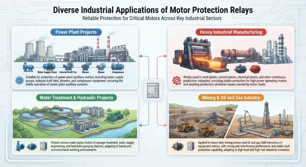
LV Industrial Motors
Low-voltage industrial motors are the workhorses of manufacturing facilities, running pumps, fans, conveyors, and processing equipment across countless production lines.
| Aspect | Details |
|---|---|
| Typical Power Range | 0.55kW ~ 500kW |
| Common Fault Risks | Overload, phase loss, voltage unbalance, stall, frequent starting |
| Recommended Products | GMP Series / NJBK2 Series / TeSys T (LTMR) |
| Key Protection Functions | Thermal overload (Class 5-30), phase loss/unbalance protection, locked rotor protection, short circuit protection, PTC temperature monitoring |
| Application Characteristics | Frequent start-stop cycles, variable load conditions, integration with PLC/MCC systems |
| Value Proposition | Replace thermal relays with digital accuracy; reduce downtime with fault diagnostics; compact DIN-rail or panel mounting |
MV Motors
Medium-voltage motors (3kV ~ 35kV) power critical assets in heavy industries — with higher replacement costs and longer lead times, making reliable protection essential.
| Aspect | Details |
|---|---|
| Typical Power Range | 200kW ~ 10MW |
| Common Fault Risks | Winding insulation failure, stator phase-to-phase/turn-to-turn faults, bearing overheating, unbalanced supply voltage, starting current surge |
| Recommended Products | MPC3000 Series / 7SJ66 Series / 87M Differential Series |
| Key Protection Functions | Thermal overload, differential protection, negative sequence/unbalance, earth fault, locked rotor, start supervision, under/over voltage, frequency protection |
| Application Characteristics | High inrush current (6-8x FLA), long starting time (5-30 seconds), critical process continuity requirements |
| Value Proposition | Prevent catastrophic winding failures with fast fault clearing; support IEC 61850 for substation integration; comprehensive fault recording for root cause analysis |
Pump Motors
Pump motors operate continuously or intermittently across water supply, irrigation, drainage, and industrial fluid transfer applications — often running in remote or unattended locations.
| Aspect | Details |
|---|---|
| Typical Power Range | 1kW ~ 2MW |
| Common Fault Risks | Dry running, cavitation, impeller jamming, phase loss, overload due to viscosity changes |
| Recommended Products | GMP Series (LV) / MPC3000 Series (MV) |
| Key Protection Functions | Underload protection (dry run detection), thermal overload, phase loss/unbalance, locked rotor, earth fault |
| Application Characteristics | Continuous duty, variable flow conditions, outdoor or submerged installation, remote monitoring needs |
| Value Proposition | Prevent pump damage from dry running with sensitive underload detection; remote alarm and auto-restart capabilities reduce site visits |
Fan Motors
Fan and blower motors are found in HVAC systems, cooling towers, ventilation shafts, and industrial exhaust — typically running for extended periods with quadratic torque load characteristics.
| Aspect | Details |
|---|---|
| Typical Power Range | 0.75kW ~ 1.5MW |
| Common Fault Risks | Bearing failure, imbalance, belt breakage (for belt-driven fans), overloading due to damper/duct blockage, phase loss |
| Recommended Products | TeSys T (LTMR) Series / NJBK2 Series / MPC3000 Series |
| Key Protection Functions | Thermal overload (with slow response suitable for fan inertia), phase loss, unbalanced current, locked rotor, underload (belt failure detection) |
| Application Characteristics | Long running hours, high inertia, slow thermal response, critical for building climate control |
| Value Proposition | Detect belt breakage via underload monitoring; prevent motor burnout from prolonged overload; reduce energy waste with load monitoring |
Compressor Motors
Compressor motors drive reciprocating, screw, or centrifugal compressors in air compression systems, refrigeration plants, and gas processing — characterized by high starting torque and cyclic loading.
| Aspect | Details |
|---|---|
| Typical Power Range | 5kW ~ 5MW |
| Common Fault Risks | Frequent start-stop cycles, overload due to pressure build-up, locked rotor, phase unbalance, thermal stress |
| Recommended Products | GMP Series / TeSys T (LTMR) / MPC3000 Series |
| Key Protection Functions | Thermal overload (Class 10/20/30), locked rotor protection, start supervision, frequent start restriction, phase unbalance, short circuit |
| Application Characteristics | High inrush current with extended start-up, pressure-dependent load variation, often operating in explosive/hazardous environments |
| Value Proposition | Restart inhibition prevents compressor motor burnout from rapid cycling; precise thermal modeling accounts for pressure-induced load changes |
Conveyor Motors
Conveyor motors drive belt, roller, or screw conveyors in material handling, mining, logistics, and manufacturing — subject to variable loads and sudden jams.
| Aspect | Details |
|---|---|
| Typical Power Range | 1kW ~ 800kW |
| Common Fault Risks | Overload due to material buildup, mechanical jamming, belt slip, motor stall, extended starting time |
| Recommended Products | NJBK2 Series / MPC3000 Series / GMP Series |
| Key Protection Functions | Locked rotor protection, thermal overload, start supervision, undercurrent (belt breakage/slip detection), phase unbalance |
| Application Characteristics | Frequent starts under load, long acceleration time due to belt inertia, dusty or abrasive environments |
| Value Proposition | Adjustable start supervision prevents thermal damage during extended acceleration; undercurrent detection identifies belt slip or breakage to avoid material spillage |
Mining Motors
Mining motors drive crushers, mills, hoists, ventilation fans, conveyors, and slurry pumps in underground and open-pit operations — some of the harshest conditions for electrical equipment.
| Aspect | Details |
|---|---|
| Typical Power Range | 50kW ~ 10MW+ |
| Common Fault Risks | Overload from material surges, voltage dips due to weak grid, frequent heavy starts, moisture ingress, mechanical shock |
| Recommended Products | M60 Differential Series / MPC3000 Series / 87M Series |
| Key Protection Functions | Differential protection, thermal overload, short circuit, earth fault, negative sequence/unbalance, voltage/frequency protection, start supervision |
| Application Characteristics | Dusty, humid, or corrosive environments; wide voltage fluctuations; extended starting times; 24/7 continuous operation |
| Value Proposition | Ruggedized enclosures (IP54/IP65) withstand harsh conditions; differential protection detects winding faults early, preventing costly downtime; comprehensive fault records aid in predictive maintenance |
Power Plant Motors
Power plant motors drive critical auxiliary equipment — boiler feed pumps, cooling water pumps, forced draft fans, induced draft fans, coal mills, and condensate pumps — where reliability is paramount for grid stability.
| Aspect | Details |
|---|---|
| Typical Power Range | 100kW ~ 20MW |
| Common Fault Risks | Winding insulation degradation, bearing overheating, phase-to-phase faults, earth faults, voltage sags/swells |
| Recommended Products | 7SJ66 Series / M60 Differential Series / MPC3000 Series |
| Key Protection Functions | Differential protection, thermal overload, negative sequence, earth fault, over/under voltage, frequency protection, breaker failure protection |
| Application Characteristics | Continuous critical duty, integration with plant DCS, compliance with utility grid codes, high fault current levels |
| Value Proposition | High-speed fault clearing protects both motor and upstream transformers; IEC 61850 GOOSE messaging enables fast inter-tripping with switchgear; detailed event logs assist in post-fault analysis for utility reporting |
Water Treatment Motors
Water and wastewater treatment facilities rely on motors for pumps, aerators, mixers, clarifiers, and chemical dosing systems — often in damp, chemically aggressive environments with varying process loads.
| Aspect | Details |
|---|---|
| Typical Power Range | 0.75kW ~ 500kW |
| Common Fault Risks | Overload due to sludge buildup, phase loss, bearing failure, moisture ingress, frequent starts |
| Recommended Products | GMP Series / TeSys T (LTMR) / NJBK2 Series |
| Key Protection Functions | Thermal overload, phase loss/unbalance, underload (loss of prime/dry running), earth fault, PTC temperature monitoring |
| Application Characteristics | High humidity, outdoor installations, variable flow conditions, integration with SCADA/RTU for remote monitoring |
| Value Proposition | Sensitive earth fault detection prevents equipment damage from moisture-related insulation degradation; underload protection shuts down pumps in dry-run conditions; Modbus/Profibus connectivity supports centralized plant management |
For tailored protection solutions specific to your motor application, please contact our application engineering team for a detailed selection and configuration recommendation.
Motor Protection Relay Manufacturing Process
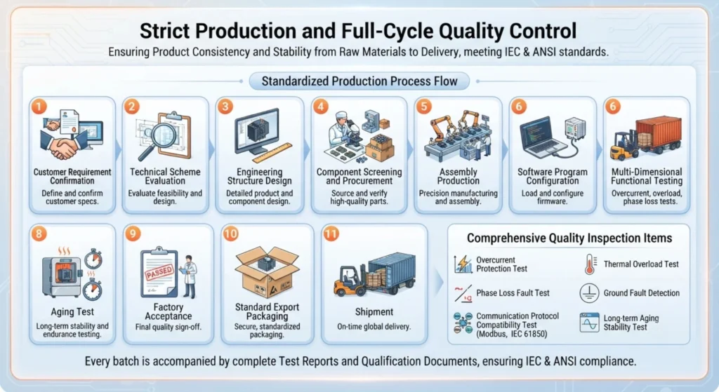
Our manufacturing process follows a strictly controlled, step-by-step workflow — from engineering design to final shipment — ensuring every relay meets our rigorous quality standards before leaving our facility.
Engineering Design – Each product begins with system architecture definition, schematic capture, PCB layout, and protection algorithm development, with design reviews conducted at every milestone to validate performance targets.
Component Selection – We source only industrial-grade components from qualified suppliers, with 100% incoming quality inspection (IQC) and traceability records maintained for every batch.
PCB / Hardware Assembly – Assembly takes place in ESD-safe workstations using automated SMT placement, precision through-hole soldering, CT/PT termination, and IP-rated enclosure sealing, with torque-controlled terminal connections.
Firmware Loading – The latest verified firmware is flashed into each microcontroller, followed by configuration parameter initialization and checksum validation to ensure code integrity.
Relay Calibration – Using traceable 0.05-grade reference sources, we perform two-stage calibration: gain/offset trimming and full-system accuracy adjustment, with temperature compensation to maintain precision across the entire operating range.
Functional Testing – Automated test benches verify basic operations: power supply, digital I/O, HMI display, LED indicators, and communication port readiness.
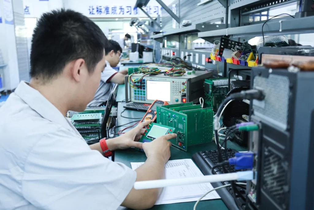
Protection Function Testing – Each relay undergoes 100% protection function verification against simulated fault conditions — injecting precise current/voltage signals to validate trip accuracy, time delay curves, and coordination with customer-defined settings.
Communication Testing – We confirm seamless integration with industrial networks by testing all supported protocols — Modbus RTU/TCP, Profibus, IEC 61850, EtherNet/IP, and others — including register mapping and data exchange integrity.
Factory Acceptance Testing (FAT) – For project-based orders, we conduct witnessed testing with customer representatives, demonstrating protection functions, communication handshake, and end-to-end trip verification against approved test procedures.
Final Inspection – A comprehensive outgoing quality check covers electrical performance, mechanical integrity, cosmetic appearance, labeling, and documentation completeness, ensuring every unit is ready for panel installation.
Packaging & Shipment – Each relay is securely packaged with anti-static and shock-proof materials, accompanied by calibration certificates, test reports, and user documentation, then dispatched with full traceability records.
This end-to-end manufacturing process ensures that every motor protection relay we deliver is reliable, accurate, and ready for immediate commissioning in your application.
Motor Protection Relay Testing and Quality Control
Quality is not an afterthought in our production — it is embedded at every stage of manufacturing. Our comprehensive testing and quality control regime ensures that every motor protection relay delivered to our customers performs with precision, reliability, and consistency, even under the most demanding industrial conditions.
Functional Testing
Functional testing serves as the first gate in our verification process, confirming that every relay operates as intended at a basic level before proceeding to more specialized tests.
| Item | Details |
|---|---|
| Test Scope | Power-on verification, LCD/LED display functionality, keypad and HMI response, digital I/O status, analog acquisition channels, alarm and trip dry contact switching |
| Test Standard | 100% verification of all basic functions; any anomalous unit automatically enters the rework process |
| Test Equipment | Automated functional test bench + custom test fixtures |
| Pass Criteria | Normal power startup; no missing segments or flickering on display; correct key response; I/O status feedback consistent with control commands |
| Recording | Each unit generates an independent test log containing test steps and comparison between measured and expected values |
Protection Function Testing
Each protection element is individually verified against simulated fault conditions to guarantee accurate and timely operation when real faults occur.
| Item | Details |
|---|---|
| Test Scope | Individual verification of all protection elements: thermal overload (all Class curves), instantaneous short-circuit, locked rotor, phase loss/reversal/unbalance, earth fault, over/under voltage, over/under frequency, start supervision, underload, differential protection, etc. |
| Test Method | Precision current/voltage sources inject simulated fault signals, covering multiple points across the protection setting range and boundary values |
| Test Standard | Trip accuracy: within ±2% of setpoint; trip time delay error: ≤±3% or ≤±40ms (whichever is greater); inverse-time curve matching verification |
| Test Equipment | High-precision three-phase current/voltage source (accuracy 0.05 class), digital oscilloscope, high-precision timer |
| Pass Criteria | Trip values and time delays for all protection elements meet accuracy requirements; no maloperation or failure to operate |
| Differentiated Testing | For differential protection series, additional verification of dual-slope restraint curves and operating boundaries across all restraint zones |
Accuracy Testing
Measurement accuracy is the foundation upon which all protection decisions are built. We verify accuracy across the full dynamic range of current and voltage inputs.
| Item | Details |
|---|---|
| Test Scope | Current measurement accuracy, voltage measurement accuracy, power/energy metering accuracy (applicable models), frequency measurement accuracy |
| Test Method | Standard source outputs multiple calibration points (covering 10%, 20%, 50%, 80%, 100%, and 120% of range), recording deviation between measured values and standard values point by point |
| Test Standard | Current/voltage measurement accuracy: ±0.5% FS (typical); frequency accuracy: ±0.01Hz; power accuracy: ±1.0% (applicable models) |
| Test Equipment | 0.05-class three-phase standard power source, 0.02-class standard meter, high-precision digital multimeter |
| Pass Criteria | All test point deviations within declared accuracy specifications; linearity qualified; repeatability verification passed |
| Additional Verification | PTC/NTC thermistor input circuit equivalent resistance injection accuracy verification (temperature measurement accuracy ≤±2°C) |
Communication Testing
Modern motor protection relays must seamlessly integrate with plant automation and SCADA systems. We verify every communication interface under real-network conditions.
| Item | Details |
|---|---|
| Test Scope | Physical layer testing (RS-485 level, fiber optic power, Ethernet connectivity); protocol layer testing (Modbus RTU/TCP, Profibus DP, IEC 61850 MMS/GOOSE, EtherNet/IP, DNP 3.0, etc.); register mapping read/write verification; communication response time testing |
| Test Method | Relay connected to an actual communication network; master station simulation software performs full register scan read/write to verify communication stability and data consistency |
| Test Standard | Packet loss rate <0.1%; response time compliant with protocol specifications; register mapping 100% correct; GOOSE message transmission/reception normal (applicable models) |
| Test Equipment | Communication protocol analyzer, network switch, master station simulation software, fiber optic power meter |
| Pass Criteria | All configured communication ports and protocols pass verification; data read/write error-free; alarms and events actively reported correctly |
Environmental Testing
Industrial environments are harsh — temperature extremes, humidity, vibration, and electromagnetic interference are daily realities. We subject our relays to environmental stress testing to ensure they withstand real-world conditions.
| Item | Details |
|---|---|
| Test Scope | High-temperature operation test (+85°C/72h), low-temperature startup test (-40°C/48h), temperature/humidity cycling test (-40°C~+85°C, RH 93%), vibration test (10Hz~150Hz, 2g), shock test (15g/11ms) |
| Test Method | Environmental chamber with programmed temperature/humidity cycling; vibration table per IEC 60068-2-6; shock per IEC 60255-21-1 |
| Test Standard | Complies with IEC 60255 series (environmental requirements for measuring relays and protection equipment); EMC immunity per IEC 61000-4 series (ESD, burst, surge, RF radiation, etc.) |
| Test Equipment | Temperature/humidity chamber, electrodynamic vibration test system, shock test system, EMC test system (ESD gun, surge generator, burst generator, etc.) |
| Pass Criteria | No electrical parameter drift beyond tolerance after environmental testing; no mechanical damage (cracks, deformation, loosening); communication normal; protection functions intact |
| Execution Method | Batch sampling on regular production (minimum 2 units per batch); 100% environmental screening available upon customer request for special projects |
Insulation Testing
Dielectric strength and insulation integrity are critical for personnel safety and equipment protection in high-voltage installations.
| Item | Details |
|---|---|
| Test Scope | Insulation resistance test (main circuit to enclosure, main circuit to auxiliary circuit, auxiliary circuit to enclosure); dielectric strength test (hipot test); impulse voltage test |
| Test Method | Insulation resistance: 500V/1000V megohmmeter test, insulation resistance ≥100MΩ (at room temperature); hipot test: apply 2kV (or per standard requirements) power frequency voltage for 1 minute, no breakdown or flashover; impulse voltage: apply 5kV (1.2/50μs waveform) positive and negative 3 times each |
| Test Standard | IEC 60255-5 (insulation coordination requirements), IEC 60947-4-1 (low-voltage switchgear and controlgear) |
| Test Equipment | Insulation resistance tester, hipot tester, impulse voltage generator |
| Pass Criteria | Insulation resistance qualified; no breakdown or flashover during hipot test; no damage from impulse test |
| Execution Method | 100% insulation resistance test and hipot test on every relay; impulse voltage test performed on batch sampling basis |
FAT Before Shipment
For project-based and customer-specific orders, Factory Acceptance Testing provides documented, witnessed proof that each relay meets contract specifications before it leaves our factory.
| Item | Details |
|---|---|
| Test Scope | Per customer-approved FAT procedure, covering: visual and mechanical inspection; electrical parameter verification; step-by-step protection function demonstration (with actual fault signal injection); communication handshake (with customer SCADA/PLC simulator or actual system); end-to-end trip circuit verification; special function confirmation |
| Execution Method | Witnessed by customer representative on-site (or remote video witnessing); our test engineer performs operations while customer confirms each step result |
| Test Standard | Based on contract technical specifications, approved test procedure, and mutually signed acceptance criteria |
| Output Documentation | FAT report (with step-by-step test records, test curves/screenshots, witness signatures, test engineer signature, date); calibration certificate (with traceability information); factory certificate of conformity |
| Post-Pass Actions | Relays can proceed to final packaging and shipment only after customer signs the FAT report; any non-conforming items are immediately rectified and re-tested |
| Additional Services | Photos/video recordings of test process available upon request; remote real-time screen sharing of test displays available |
This comprehensive testing and quality control system ensures that every motor protection relay not only achieves optimal performance at the time of shipment, but also maintains stable and reliable operation throughout its long-term service life. Our commitment to quality spans every stage from design to delivery.
Motor Protection Relay Customization
Every motor application presents unique requirements. We offer extensive customization capabilities to tailor our motor protection relays precisely to your project needs.
Protection Function Customization
| Customization Item | Description |
|---|---|
| Function Enable/Disable | Selectively enable or disable specific protection elements (differential, underload, negative sequence, etc.) |
| Curve Customization | Custom thermal overload curves beyond standard Classes; inverse-time curves per customer formulas |
| Setting Range Adjustment | Expand or narrow protection setting ranges to match motor parameters |
| Dual Settings | Two sets of protection settings switchable via external DI or communication |
| Custom Logic | Interlock protection, process interlocking, sequence control via programmable logic |
CT/PT Input Configuration
| Customization Item | Description |
|---|---|
| CT Ratio Configuration | Support 1A/5A standard CT inputs with configurable primary/secondary ratios |
| Special CT Types | Support Rogowski coils, zero-sequence CTs, and slip-on CTs for retrofit projects |
| PT Ratio Configuration | Support 100V/110V/400V PT secondary voltages with configurable ratios |
| Input Channel Customization | Custom combinations of 3-phase current, 3-phase voltage, zero-sequence current/voltage |
| Input Range Extension | Adjust analog input ranges for special sensors or CT specifications |
Rated Current & Voltage Customization
| Customization Item | Description |
|---|---|
| Rated Current Setting | Configure per motor nameplate FLA, covering 0.1A to thousands of amps (with external CTs) |
| Rated Voltage Setting | Configure per system voltage, covering AC 110V ~ 35kV |
| Frequency Configuration | 50Hz / 60Hz switchable or locked to a specific frequency |
| CT Primary Current | Match field CT ratios for direct primary-side display and protection settings |
| Zero-Sequence Threshold | Configure sensitive earth fault detection thresholds per grounding system type |
Communication Protocol Customization
| Customization Item | Description |
|---|---|
| Standard Protocol Support | Modbus RTU/TCP, Profibus DP, Profinet, IEC 61850 (MMS/GOOSE), EtherNet/IP, DNP 3.0 |
| Protocol Customization | Custom Modbus address mapping, data format, byte order, baud rate, etc. |
| Dual-Network Redundancy | Dual Ethernet ports for ring network redundancy or dual-network backup |
| Fiber Optic Communication | Multi-mode/single-mode fiber interfaces (ST/SC connectors) for high-EMI environments |
| Proprietary Protocols | Custom development per customer protocol specifications |
Digital Input / Output Configuration
| Customization Item | Description |
|---|---|
| DI Quantity | Standard 4~8 DI, expandable up to 16 channels |
| DI Function Assignment | Each DI customizable for start/stop, reset, remote/local switching, setting group switching, external interlock, etc. |
| DO Quantity | Standard 4~6 DO, expandable as required |
| DO Function Assignment | Each DO customizable for trip output, alarm output, running indication, fault indication, remote control, etc. |
| Contact Type | NO/NC combinations optional; relay output or transistor output |
| Signal Logic | Positive or negative logic selectable per customer control requirements |
Trip Logic & Alarm Logic Customization
| Customization Item | Description |
|---|---|
| Trip Matrix Configuration | Define actions per protection element: trip, alarm, log only, close lockout, etc. |
| Trip Delay Customization | Independent adjustable delays per element; definite-time and inverse-time options |
| Alarm Threshold Setting | Independent alarm thresholds (e.g., overload alarm below trip value) for pre-warning |
| Alarm Output Mode | Customize alarm output: local LED flashing, LCD display, communication upload, DO output, buzzer, etc. |
| Trip Lockout Logic | Configure auto/manual reset logic, external lockout conditions, and safety interlock strategies |
| Event Classification | Custom event classification and storage priority to ensure critical faults are not overwritten |
Display Configuration
| Customization Item | Description |
|---|---|
| Display Language | Multi-language support (Chinese, English, and others upon request) |
| Layout Customization | Customize main screen display priorities (phase currents, voltages, power, load rate, etc.) |
| Fault Display Format | Customize fault pop-up format: fault type, fault value, timestamp |
| Waveform Display | Real-time waveform or fault recording summary on LCD (applicable models) |
| Custom Screens | Add customer logo on startup screen; display company name and project information |
| LED Indicator Customization | Customize LED function definitions (power, communication, trip, alarm indicators) |
Housing & Enclosure Customization
| Customization Item | Description |
|---|---|
| Mounting Type | Panel cutout mounting, DIN-rail mounting, 19-inch rack mounting (optional) |
| Protection Rating | Standard IP42 (front) / IP20 (body); optional IP54, IP65 (fully sealed) |
| Enclosure Color | Standard RAL 7032 / RAL 9005; custom colors available upon request |
| Enclosure Material | ABS engineering plastic (standard), flame-retardant PC, metal housing (high protection or hazardous areas) |
| Nameplate Customization | Customer logo, model, technical parameters, barcode per requirements |
| Terminal Type | Plug-in terminals, screw clamp terminals, spring terminals, or quick-connect terminals |
| Dimensions | Custom dimensions per panel cutout requirements (subject to minimum electrical clearance) |
Panel Integration
| Customization Item | Description |
|---|---|
| Cutout Size | Standard sizes (96×96mm, 144×144mm) or custom per customer drawings |
| Depth Adjustment | Adjust housing depth to accommodate limited back-panel space |
| Terminal Location | Top/bottom/rear terminal placement per panel layout |
| Accessories | Mounting brackets, dust covers, wiring harnesses, wiring diagram stickers |
| Complete Solutions | Full motor protection panel solutions including relays, CTs, PTs, and operator panels |
Firmware Customization
| Customization Item | Description |
|---|---|
| Custom Algorithm Development | Develop new protection algorithms per customer specifications (with technical documentation) |
| Custom Logic Programming | Customer-defined automation logic via CFC/Ladder editor |
| Special Feature Development | Custom motor starting strategies, energy-saving control, predictive maintenance algorithms, etc. |
| Firmware Version Locking | Lock specific firmware versions for project consistency and long-term stability |
| Firmware Naming | Custom firmware version numbers and device name display per customer request |
| Source Code Licensing | Source code licensing and joint development for strategic partners (with agreement) |
OEM / ODM Services
| Service Type | Description |
|---|---|
| OEM (Private Label) | Custom nameplates, packaging, manuals, colors, and logos; core hardware and firmware provided by us with full manufacturing and testing |
| ODM (Custom Design) | Full custom development from concept or based on existing platforms — industrial design, hardware, firmware, protection algorithms, communication protocols, etc. |
| Enclosure Moulding | Custom enclosure shapes and colors with proprietary moulds (MOQ applies) |
| Deep Customization | Joint product definition; we handle R&D and manufacturing, you handle market and sales; IP ownership negotiable |
| Long-Term Supply | Long-term supply agreements ensuring component availability and stable delivery; no product obsolescence risk |
| Certification Support | Support for product certifications in target markets (UL, CSA, CE, CCC, GOST, ABS, etc.) |
| Service Process | Requirements gathering → Technical proposal → Sample development → Prototype testing → Customer validation → Mass production → Ongoing support |
Why Customize with Us?
| Core Advantage | Description |
|---|---|
| Vertical Integration | Full in-house control from hardware to firmware, algorithms to testing — no technical barriers |
| Flexible MOQ | Low minimum order quantities for OEM/ODM projects; small batches supported for pilot projects |
| Quick Response | Standard customization: 4~8 weeks; simple configuration adjustments: 1~2 weeks |
| Strict Confidentiality | NDA signed to protect your design solutions and business information |
| Quality Assurance | Custom products share the same quality system and testing standards as standard products |
| Ongoing Support | Firmware upgrades, spare parts supply, and technical consultation throughout product lifecycle |
For customization inquiries, please contact our technical sales team with your project specifications — we will provide a tailored solution proposal within 48 hours.
Motor Protection Relay Engineering Support
We don’t just sell relays — we deliver complete engineering solutions. From project conception through to commissioning and ongoing operation, our engineering team works alongside you to ensure your motors are protected with the right scheme, correctly configured, and reliably integrated into your control infrastructure.
Motor Protection Selection
Selecting the right protection relay requires comprehensive analysis of motor parameters, starting methods, load characteristics, and system configurations.
| Service Item | Details |
|---|---|
| Application Analysis | Evaluate motor type, starting method, load characteristics, and duty cycle |
| Protection Requirements Definition | Define protection function list based on motor criticality and fault risks |
| Product Selection Recommendation | Recommend best-fit relay series and models with technical comparison tables |
| System Compatibility Assessment | Verify compatibility with existing CT/PT, communication networks, SCADA/PLC, and installation space |
| Selection Report Output | Issue formal selection report including recommended model, configuration list, and technical justification |
Protection Scheme Design
For MV systems, critical processes, or special environments, we design coordinated primary and backup protection schemes.
| Service Item | Details |
|---|---|
| Protection Coordination Study | Analyze coordination between upstream and downstream protection devices for selectivity |
| Protection Configuration Scheme | Determine primary and backup protection combination strategies |
| Setting Strategy Development | Develop complete setting strategies including start blocking and running activation |
| Single-Line Diagram Markup | Mark relay locations, CT/PT connection points, and protection zones |
| Solution Documentation | Deliver complete documentation including configuration diagrams, setting lists, and logic descriptions |
Relay Setting Support
Incorrect settings can cause maloperation or failure to trip. We provide expert setting support throughout the project lifecycle.
| Service Item | Details |
|---|---|
| Setting Calculation Service | Calculate protection settings based on motor parameters and system data |
| Setting Table Preparation | Provide standardized setting tables with set values, delays, enable status, and logic |
| Setting Verification | Verify setting behavior and selectivity using fault simulation software |
| On-Site Setting Tuning | Assist with fine-tuning and optimization during trial operation |
| Setting Management | Provide backup tools and change record management for traceability |
| Emergency Support | 24/7 setting review and adjustment recommendations for maloperation/failure-to-trip events |
Wiring Guidance
Correct wiring is fundamental to reliable protection system operation. We provide detailed wiring support.
| Service Item | Details |
|---|---|
| Terminal Wiring Diagrams | Provide detailed terminal wiring diagrams for each relay |
| Typical Wiring Schemes | Cover DOL, star-delta, soft starter, VFD, and other starting circuits |
| CT/PT Wiring Guidance | Specify polarity connections, phase assignments, and common terminal handling |
| Shielding & Grounding Recommendations | Provide grounding strategies for communication cables, signal cables, and enclosure |
| Wire Gauge & Color Recommendations | Recommend wire gauges and color codes per current levels and standards |
| Wiring Checklist | Provide pre-energization self-check checklist |
Communication Configuration
Configure all communication interfaces to ensure seamless data exchange with SCADA/PLC systems.
| Service Item | Details |
|---|---|
| Communication Protocol Configuration | Configure baud rate, IP address, station address, and other protocol parameters |
| Register Mapping Definition | Provide complete mapping tables, customizable per customer point lists |
| SCADA/PLC Integration | Assist with data integration with mainstream SCADA and PLC systems |
| GOOSE Configuration | Configure IEC 61850 GOOSE subscribe/publish and redundancy settings |
| Communication Testing | Verify data read/write, event uploads, and remote control functions |
| Communication Troubleshooting | Provide systematic troubleshooting for interruptions and data anomalies |
Factory Acceptance Testing (FAT)
Before shipment, we offer witnessed FAT to provide documented proof of product performance and functionality.
| Service Item | Details |
|---|---|
| FAT Procedure Preparation | Prepare detailed test procedures per contract specifications |
| Customer Witness Testing | Customer on-site or remote video witness of complete test process |
| Protection Function Demonstration | Step-by-step demonstration with fault signal injection to verify trip values |
| Communication Integration Verification | Connect to customer SCADA/PLC simulators for protocol verification |
| Custom Feature Confirmation | Dedicated verification of customer-customized functions or logic |
| FAT Report Signing | Issue formal report with customer signature for acceptance |
| Test Video Recording | Provide video recordings of key test items upon request |
Site Acceptance Testing (SAT)
After delivery and installation, we support customers with SAT to validate system performance under actual site conditions.
| Service Item | Details |
|---|---|
| SAT Procedure Preparation | Prepare test procedures based on actual site conditions |
| On-Site Test Execution | Deploy engineers on-site or remote guidance for primary/secondary injection testing |
| System Integration Testing | Coordinate with upstream/downstream protection and control systems |
| On-Site Setting Verification | Verify setting suitability under actual load conditions; fine-tune as needed |
| SAT Report Preparation | Issue test report for customer acceptance and archiving |
| Open Issue Resolution | Track and resolve any issues identified during SAT until closure |
Commissioning Support
The commissioning phase is where the protection system is proven under live conditions. We ensure smooth start-up.
| Service Item | Details |
|---|---|
| Pre-Commissioning Inspection | Provide checklists for wiring verification, insulation testing, parameter checking, and communication |
| On-Site Commissioning Guidance | Deploy engineers on-site or provide remote support |
| Start-Up Monitoring | Real-time monitoring during first start and trial operation to prevent maloperation |
| Load Test Verification | Verify measurement accuracy and protection functions under loaded conditions |
| Commissioning Report | Provide summary report documenting process, parameters, and acceptance results |
| Operator Training | Provide training on relay operation and basic fault diagnosis for O&M personnel |
Troubleshooting
Field issues can arise. We respond quickly to minimize downtime.
| Service Item | Details |
|---|---|
| Fault Diagnosis Process | Systematic process: symptom confirmation → data collection → cause analysis → solution → verification |
| Remote Diagnostic Support | Quick response via phone/email/remote desktop to guide on-site handling |
| On-Site Emergency Support | Dispatch engineers to site within 24 hours for major faults |
| Fault Record Analysis | Read event records and waveform data for in-depth root cause analysis |
| Report & Recommendations | Provide analysis report with causes, corrective actions, and preventive recommendations |
| Emergency Spare Support | Rapid spare relay shipment for critical applications to minimize downtime |
Our Engineering Support Commitment
| Commitment | Details |
|---|---|
| Full Lifecycle Support | Continuous technical support from selection to replacement |
| Quick Response | Technical inquiries within 2 working hours; emergency on-site dispatch within 24 hours |
| Professional Team | Application engineers with power protection backgrounds; average 10+ years experience |
| Comprehensive Documentation | Complete documentation output for all services (schemes, reports, records) |
| Multi-Language Capability | Bilingual technical communication in Chinese and English for international projects |
| Ongoing Training | Regular technical seminars and online training for customer team development |
For engineering support inquiries, please contact our application engineering team — we are ready to assist from concept to commissioning and beyond.
Contact Beijing Autony Power for Your Motor Protection Relay Project
Looking for a reliable motor protection relay manufacturer with strong technical strength, stable product quality, and professional overseas service? Beijing Autony Power provides one-stop motor protection solutions from scheme design, product customization, factory production to global after-sales service.
Whether you are an EPC contractor, power station operator, or industrial project owner, we can provide low cost motor protection relay products and professional technical support matching your project standards. Contact our professional international sales and engineering team now to get a customized technical proposal and exclusive quotation!



About Author

Hello, I'm Leno Zhang. I have 15 years of experience in the power relay protection industry with extensive pre-sales and after-sales project experience. Our company specializes in various complete sets of relay protection and automation equipment. I can assist customers in solving all practical on-site project challenges and provide optimal integrated solutions.
Tell Us Your Requirement
High Quality
Stable performance, reliable design, ensuring safe operation for power system protection and grid stability.
Fast Delivery
Timely delivery to support your urgent orders and project schedules efficiently and professionally at any time.
Best Warranty
Professional Warranty: Reliable after-sales support for stable relay protection and long-term customer satisfaction.