
-
Leon Zhang Sales Manager
-
Email: sale@relayprotect.com
-
Phone/WhatsApp: +86 13655813266
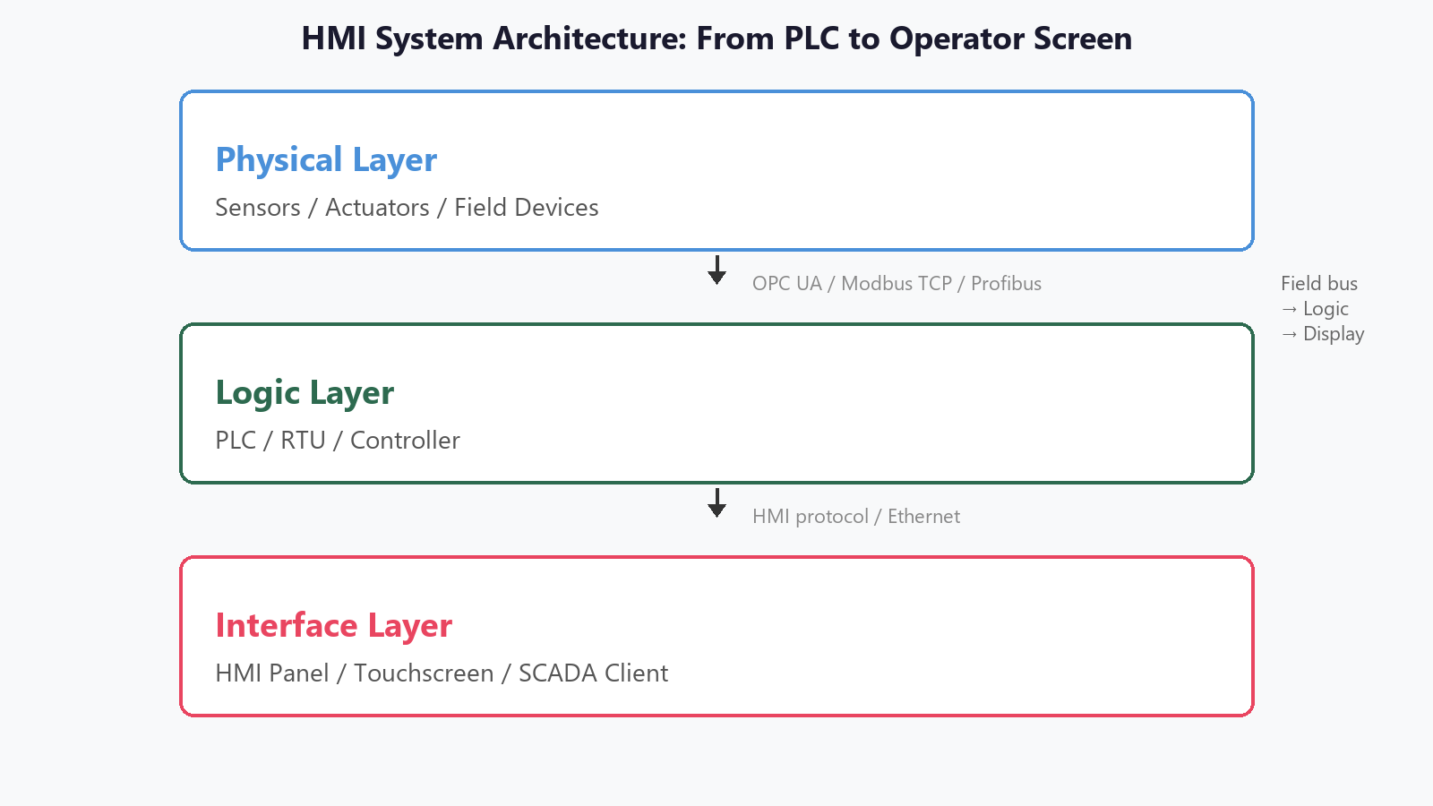
Choosing an HMI System: Panel, Protocols and Sizing
An HMI system links operators to automation logic. This guide covers hmi panel types, industrial hmi selection, and hmi control panel layout.
An HMI system is the operator-facing layer that turns raw process data into screens, alarms, trends, and control commands a human can read and act on. In a substation it is what lets the on-site operator see bus configurations, acknowledge a trip, and close a breaker without opening a cabinet. In practice most substations run several HMI systems in tiers, one per bay or cabinet, all reporting to the same operator. This guide covers assembly, sizing, and when the HMI system is the right tool instead of a full SCADA client. Where the load is light and the bay count small, a single HMI system is enough; where the estate spans several bays, HMI systems sized per bay keep each operator’s screen legible.
At a Glance
- Role: operator interface between field devices and human decision-making The HMI systems in a substation are the operator interface between field devices and human decision-making.
- Typical form factor: panel-mounted touchscreen, 7- to 22-inch, IP65 front
- Common protocols: Modbus TCP, IEC 61850 MMS, DNP3, OPC UA, EtherNet/IP
- Pairing: usually one HMI drives one PLC/RTU; multi-PLC needs SCADA server
- Design standard anchor: IEC 61131-3:2024, IEC 62443-3-3:2022, IEC 61499-2:2023
- Not a substitute for: the protection relay or the PLC logic that it displays
Written by RelayProtect Editorial, protection engineering desk. Reviewed by the RelayProtect engineering team. Last reviewed: 2026-10-27.
Quick Rules for HMI System Selection
- Match the screen to the sight-line, not the catalog.
- Glove rating is a hard requirement in a substation.
- Never let the screen decide the trip.
- Keep a spare display on the shelf.
- Get the logic signed off before the first screen is drawn.
What an HMI System Actually Is
An HMI system is not a single box. It is four things working together. The first is the display, usually a ruggedized touch panel. The second is the processing core that reads inputs, runs the screen logic, and decides what to show. The third is the communication link, most often an Ethernet or serial port wired to a PLC, RTU, or gateway. The fourth is the application, the set of screens and logic that maps real I/O points to on-screen objects. Strip out any one of the four and you no longer have a functioning HMI. Read across a whole station and the four layers repeat, so a fleet of HMI systems is just the same handshake run many times, once per panel.
You have either a display, a network cable, or a piece of software, but not the interface that operators rely on. Think of it as the handshake between the process and the person: the display is the face, the controller is the reflex, the communication link is the nerve path, and the application is the vocabulary the two use to talk.
Selecting a relay for a live project?
Send the system voltage, CT ratio and tripping scheme. Our engineers confirm the model and reply within 12 hours.
When one of the four is missing or degraded, the operator does not get a warning, they get a screen that lies to them, and in a substation a lying screen is worse than no screen at all, because the operator has already stopped looking at the breaker and started looking at the number. The display, in short, is that handshake, and a broken one costs you the plant.
That distinction matters when you write a spec. Saying “add an HMI” is not a complete requirement. You need to state the display size, the I/O point count, the communication protocol to the controller, the alarm and trend retention, and the enclosure rating for the installation site. Each of those feeds a different part of the display and has its own cost. Put the numbers in the spec. When the spec covers more than one cabinet, the HMI systems share one protocol and one alarm dictionary so the operator reads them the same way.
Choosing the Right HMI Panel
HMI panel size is the first decision, and the HMI panel choice is the real constraint. Machine-level applications, a single pump cabinet, a soft-starter, or a compact control station, run on a 7- to 10-inch panel. A substation control room that shows a one-line plus an alarm list wants 15 inches or more. The physical panel must also match the enclosure: wall-mounted, flush-mounted in a cabinet door, or on a pedestal for a walk-in control room. The same physical panel size can behave very differently depending on the viewing distance, so check the sight-line from wherever the operator actually stands.
A 15-inch screen that looks comfortable from two meters can be unreadable from the five-meter position of a large control-room desk, and that is the number that matters on the shop floor, not the spec sheet.
Second is the input surface on the HMI panel.
Capacitive touch is cheap and responsive but poor with gloves; resistive and projective-capacitive touch work with industrial gloves, which is why they dominate in a distribution environment. A panel that operators will touch in winter with leather gloves on will not be reliable with a bare capacitive screen. The glove rating is usually tested with a 1 mm to 2 mm nitrile glove, and for a substation that is the minimum you should accept. If the operator is switching gear in a cold room, the test condition has to match that reality.
Third is the processor inside. A panel display with only an embedded controller is correct for a fixed alarm-and-trend job. When the same screen has to run a historian, a SCADA client, or on-board video, you need a panel PC form with real RAM, a hard drive, and an expansion slot. The two are not interchangeable and cost quite differently.
A final practical check: ask the vendor for the minimum order lead time, because embedded displays are made to order and a shortage at the manufacturer can push a commissioning date by six to eight weeks.
For a distribution project with a fixed energization date, confirm the panel ships and is on the dock before the protection and control builders arrive at the site.
Finally, match the panel to the redundancy architecture it will sit in. A single display driving two PLCs is convenient until one scan misses, and the operator sees stale data on a healthy controller. In a substation where two breakers are behind that one screen, the miss is not a cosmetic problem.
Ask whether the panel will show a stale-data flag when a controller drops off the bus, and whether the operator can isolate one side without touching the other. The panel is cheap; the moment of confusion on a live panel is not.

Industrial HMI vs Consumer Displays
Industrial hardware is built for a much harder life than the touch screen in a retail kiosk or a consumer appliance. An industrial display is rated for a temperature range that spans from well below freezing to above 50 °C, a front panel that resists dust and wash-down, and a mean time between failures measured in years, not the couple you get from consumer glass.
The spec sheet will list the two temperatures separately: the operating range, which is the window the display can actually keep running, and the storage range, which is only how long you can leave it in a box.
A control-room panel lives in the operating range, and the operating range is the number that determines whether the screen survives a hot summer or a winter shutdown.
The display also has to keep running when the plant around it does not. Power dips, a momentary loss of the field bus, or a noisy ground will glitch a consumer screen. A consumer panel burns in on a static one-line within a year. An industrial unit is designed to ride through those, log the event, and come back on the correct screen instead of freezing.
In a distribution substation, where an unattended fault can leave an operator with seconds to react, that ride-through behavior is the whole point of choosing the industrial HMI over a cheaper display.
The ride-through is tested in the vendor drop-test and brownout reports, and those reports are part of a procurement that is done properly. Ask for them by name.
Longevity is the final tell. An industrial display that has been obsolete on the shelf for three years is a red flag for a panel you are commissioning today.
Before you sign a purchase order, check that the model is still in production, that spare parts are available for a reasonable period, and that the software tooling still runs on the operating system you will standardize on.
Two more practical checks: the display must list its operating temperature range in the datasheet, not just the storage range, because a substation control room in summer can hold above 45 °C for weeks. An analogue reading that drifts by 2% a year is usually a panel problem, not a sensor problem. And confirm that the toolchain you will use to build the screens is still supported on your standard operating system; a vendor that silently drops support for the old editor leaves a fleet of panels that can never be re-pointed after a firmware update.
The last consideration is serviceability. When a backlight fails or a touch cell gets stuck in a substation control room, you do not get to RMA the whole panel to another country and wait eight weeks for it to come back. The display should be designed so the backlight and the power board can be replaced in the field, and the vendor should be able to ship you the two boards in a week. Put the field-serviceability requirement in the spec, because the alternative is a dark control room while the panel travels back and forth across an ocean.
One last practical point: keep a spare display on the shelf, not on the panel, for a plant that cannot afford to run without the screen.
The spare does not need to be the same model, it needs to run the same software and read the same screen file. A panel that is down for two weeks while a replacement ships is a panel that was never bought with a spare in the budget, and that two-week gap is the exact window when an operator is most likely to make a mistake because the information they need is not in front of them.

Designing the HMI Control Panel
The HMI control panel is the physical cabinet that houses the HMI, its power supply, its communication cabling, and the wiring that reaches the field devices. Get this wrong and the screen is only as good as the box it sits in. Start with the enclosure rating: an outdoor or wash-down substation position needs IP65 at minimum on the front, and the control panel must keep the rear of the display dry while the operator works from the front. The rating is not just a number on the plate. It is the sum of the gasket, the door seal, the cable gland, and the position of the panel in the building, and a panel that is rated IP65 but sits in a location where condensation forms on the back will still corrode. Ratings are bench tests.
Inside the HMI control panel, layout is the subtle skill. The HMI system sits where it can be read from a natural standing position, the communication modules and I/O terminals cluster behind it, and the power supply and breaker have room to be serviced without pulling the whole faceplate.
A poorly laid control panel is one where the technician has to remove forty other parts to reach a single terminal.
The control panel is also where you enforce the separation between the operator face and the interlock and control wiring that reaches the breaker, the contactor, and the switchgear. One more point: the panel door should open far enough to service the rear of the HMI without pulling the faceplate out of the cabinet, and the hinges and gasket must survive the number of door cycles you expect over a fifteen-year life.
Specify the door cycle rating in the purchase order; it is the number that decides whether the panel survives routine maintenance or starts to leak moisture after a few years of opening and closing.
The panel is also where grounding and shielding come together.
The display itself is grounded to the panel frame, and the control wiring that reaches the relay is shielded and terminated on one end, not both. A shield that is terminated at both ends creates a ground loop, and that loop is what couples a switching transient into the analog input and turns a stable reading into a wandering one. Feed the display from a 24 V supply, keep the 12 V logic rail referenced to the panel frame, and the reading stops drifting against a 60 Hz switching transient.
The panel builder who does the wiring right is the one you trust at 2 a.m., and the panel that separates the operator face from the interlock wiring is the one that keeps the breaker and the screen from disagreeing about whether the line is live.
Finally, budget for the panel to be serviceable for its full life.
A control panel that is welded shut with a single access door is a panel that will be cut open with a grinder the first time the power supply fails. Design the panel so the display, the supply, and the communication modules each have their own access, and the panel lives in a serviceable state for the decade it spends at the substation. Serviceability is a budget line.

Sizing, Protocols, and Specification
The HMI systems in a distribution substation are spec’d per bay: name the point count, the protocol and the retention per screen, and the display tier follows.
Point count drives the HMI spec more than almost anything else. Count every displayed value, every alarm, every trend, every command, and every interlock that the operator will touch. Rule of thumb: an embedded unit handles a few hundred points comfortably; once you pass a couple thousand you want a panel PC or a dedicated SCADA client, because the scan time and trend history will start to push the small controller. Count them before you size the display. Across a station, each bay’s HMI systems are sized to their own point count, and the total scan time is the sum of the per-bay figures.
The protocol between the HMI and the controller is the second spec.
In a distribution environment IEC 61850 is the native language between the relay and the gateway, so the HMI usually talks to a protocol gateway that bridges MMS to Modbus TCP or DNP3. If the controller is a conventional PLC, Modbus TCP or the vendor proprietary protocol is the direct path. State the protocol, the maximum scan time, and the number of simultaneous connections in the HMI requirement, and the bidders will price it correctly. A third spec item is trend retention.
An operator who is diagnosing a transient fault two hours ago needs a trend buffer that goes back at least that far, and often much longer.
Specify the number of channels and the retention period in hours, not just the raw memory size, because the effective retention depends on the scan interval and whether the HMI compresses the data or stores it point-by-point. A fourth spec item is the alarm strategy, which is where most panels quietly fail. An alarm that flickers every time a value crosses the threshold and then crosses back is not an alarm, it is a light that is on all the time. Specify the deadband.
Specify the delay before an alarm acknowledges, and cap the number of active alarms the screen shows before it scrolls.
An operator who is looking at forty active alarms at once is not monitoring the plant, they are drowning in it. Cap the list. The deadband and the alarm cap are the two numbers that decide whether the panel is a tool or a source of stress, and neither one is obvious from a catalog price comparison.
Nail those three, and the HMI system you buy is the one the operator will still trust in year ten.
When an HMI System Is the Wrong Choice
The screen is the wrong tool in three clear cases, and the pattern behind all three is the same: the interface adds cost without adding a decision the operator has to make. A fourth boundary is different in kind. The boundary applies to HMI systems in general: none of them should ever decide a trip, only display and arm one.
- Fixed indication with no operator input. Five status lamps on one machine do not need a touch screen; solid-state indicators and a conventional control panel are cheaper and more reliable.
- No operator at the panel. If the only person reading the process sits in a central SCADA room, a field HMI adds cost with little value. Buy a thin SCADA client instead.
- Pure data logging. A dedicated recorder or a gateway with a web server stores the same values for less money and with fewer parts to fail.
The fourth boundary is a safety boundary, not an economic one.
Never let the HMI decide whether a breaker opens on a fault, and never route a trip coil command through the screen. The tripping and interlock logic belongs in the protection relay and the PLC. Sign that logic off before the first screen is drawn, because the screen is the most expensive place to absorb a change. Lock the state machine and the trip logic first, then draw the panel.
Standards and Reference Sources
The standards below are the reference anchors for the design, timing, and security claims made in this guide. Use the edition year, not the name. A bid measured against the wrong edition is not a saving.
| Standard | Covers | Edition / Year |
|---|---|---|
| IEC 61499-2:2023 | Functional safety – system hardware | 2023 |
| IEC 61131-3:2024 | PLC / HMI structured text and SFC languages | 2024 |
| IEC 62443-3-3:2022 | Industrial control network security requirements | 2022 |
| IEC 61850-7-2:2013 | Substation MMS logical device and data classes | 2013 |
| ANSI/ISA-101:2015 | Control / monitoring / data-logging design | 2015 |
| IEC 60870-5-103:2013 | Substation telecontrol – 104 protocol, DNP3 analogue | 2013 |
| IEC 61850:2013 | Substation communication – general architecture | 2013 |
HMI Selection Specification Sheet
The table below lays out the three most common deployment tiers, from a single machine cabinet to a central control room. Use it to sanity-check a bid before you price it.
| Selection item | Machine level | Substation control | Control room / SCADA |
|---|---|---|---|
| Display size | 7-10 in | 15-21 in | 22 in or large-format |
| Touch type | Resistive / PCAP with glove | Projective capacitive, glove-rated | PCAP + hard-key console |
| Point count | < 300 | 300-2,000 | > 2,000, multi-terminal |
| Controller | Embedded HMI | Panel PC HMI | SCADA client + server |
| Protocol | Modbus / vendor | IEC 61850 MMS via gateway | DNP3 / IEC 61850 / OPC UA |
| Enclosure | IP65 front, NEMA 1 rear | IP65 front, NEMA 2 rear | NEMA 4 / indoor clean |
| Redundancy | Single | Single, monitored | Redundant comms, dual supply |
Selecting a model for this scheme? Send the voltage level, CT/VT ratios and your relay list. An engineer returns a model mapping and quotation within 12 hours →
Communication Protocol Cheat Sheet
Match the protocol on the controller to the one the display can speak, and the scan time drops. A mismatch forces a gateway in the middle, and the gateway is where the latency quietly creeps in. Latency hides there.
| Layer | Native protocol | Gateway target | Typical scan |
|---|---|---|---|
| Relay (IEC 61850) | MMS / GOOSE | DNP3 or Modbus TCP | 1-5 s for state, 10 ms for GOOSE |
| Conventional PLC | Vendor / Modbus | Direct to HMI | 100-500 ms |
| Fieldbus ring | IEC 60870-5-103 | DNP3 | 2-10 s |
| Historian / SCADA | OPC UA | Direct from gateway | Variable, event-driven |
| Serial legacy | RS-485 Modbus RTU | Ethernet gateway | 500 ms-1 s |
Common Failure Modes and First Checks
Most of the problems that reach a panel are electrical, not software. Work down this list before you open the program. Most faults are wiring.
| Symptom | First check | Second check |
|---|---|---|
| Panel black on boot | Supply fuse / breaker at panel rear | Supply output voltage at display input |
| Stale values, no update | Comms link light on gateway | Scan time vs point count |
| Touch unresponsive | Glove / moisture on surface | Calibration reset |
| False alarms | Ground loop on shield | Reference of analog input |
| Freeze after power dip | Ride-through setting | Watchdog / recovery program |
| Screen flicker | Ground of display vs cabinet | EMC of supply and cabling |
Frequently Asked Questions
What does HMI stand for and how does it differ from a SCADA system?
HMI stands for Human Machine Interface. The HMI sits at the device or area level: it talks to one PLC or RTU, shows process values, and accepts operator commands. A SCADA system works across an entire distribution network, aggregating data from many remote terminals into a central dispatch view. You can run SCADA without an HMI, but almost every HMI installation pairs with a PLC or RTU behind it.
What size HMI panel should I choose for a substation control room?
For a panel-mounted control station, a 15- to 22-inch industrial HMI is the usual range. Smaller screens (10-inch and below) suit machine-level or single-cabinet applications. Size choice should follow how many concurrent trends and one-line diagrams the operator needs at a glance. A 15-inch screen handles a substation one-line with an alarm list comfortably; anything above 22 inches usually moves into a large-format control-room HMI paired with a SCADA workstation.
Can one HMI control panel drive more than one PLC?
Yes, but the topology matters. A single industrial HMI can poll two or three PLCs over Ethernet if scan time stays under 500 ms and no safety-critical loop crosses between them. Beyond three, latency and fault isolation usually argue for a dedicated HMI per PLC or a central SCADA server with client workstations. Check the communication module list in the HMI datasheet before committing to a multi-PLC design.
How often should I replace an industrial HMI in a distribution panel?
There is no fixed calendar. Two things drive the decision: display backlight hours (typically 50,000-100,000 hours rated) and connector or ribbon-cable wear. In harsh substation environments with vibration and dust, inspect connectors every two years and budget a screen swap around the 7- to 10-year mark unless the enclosure IP rating has degraded.
What is the difference between an embedded HMI and a panel PC HMI?
An embedded HMI seals the processor, memory, and communication ports into the display unit. It is cheap, compact, and fine for fixed-panel applications. A panel PC HMI is a computer built into a rugged display; it runs a full operating system, accepts expansion cards, and suits cases where you need to run SCADA client software, a historian database, or video-on-plant. The trade-off is cost and maintenance complexity.
Is an HMI system the same thing as a touch screen?
No. The touch screen is only the input surface. The HMI includes the display, the controller or logic engine behind it, the communication link to the field devices, and the software that maps I/O to on-screen objects. A touch screen with no logic or communication is just a display; call it an HMI only when the full stack is present and functioning.
Do I need an HMI in a fully remote SCADA architecture?
Usually yes, at least a minimal one. Even when a central SCADA system handles dispatch and monitoring, the local panel at the substation or pump house still needs a small HMI for on-site operators: local control, trip reset, and emergency override. Design it to degrade gracefully when the communication link to the central system drops.
How many HMI systems does a distribution substation usually run?
Most distribution substations run one HMI system per bay or cabinet, so the estate is a small fleet of HMI systems rather than one big one. The fleet is wired to a common protocol and a shared alarm dictionary so the operator reads every screen the same way. Where the bays sit behind a single operator, the HMI systems hand off to one central SCADA client instead of each running its own dispatch view.
Conclusion
Put together, a well-chosen HMI system does one job and does it well: it makes the process legible and the operator effective. Size the panel to the screens the operator actually reads, pick the industrial hardware for the environment it will survive, and lay out the control panel so the next technician does not curse you at 2 a.m. When those three are right, the HMI becomes the unglamorous interface that stands between a substation and the human who keeps it running. Get HMI systems right and the whole control room reads like one instrument instead of a row of separate ones.
Related Reading
- Understanding SCADA systems The dispatch-side view that the HMI feeds into
- PLC controller selection The logic engine that the HMI talks to
- Switchgear and one-line basics The equipment an hmi control panel represents on screen
- Protective relay selection The trip logic an HMI displays but never decides
Related guides: Switch board · Power transformer · Power distribution
For a model recommendation, send the system voltage and the load details to our engineering team. For HMI systems, send the bay count, the point count and the protocol in use; our relay desks spec the panel tier and the alarm dictionary against IEC 61850:2013 and return a setting list a walk-down can verify.
Working on a similar scheme? Send the single-line diagram, relay list and CT/VT data. Quote in 12 hours →
About Author

Hello, I'm Leon Zhang. I have 15 years of experience in the power relay protection industry with extensive pre-sales and after-sales project experience. Our company specializes in various complete sets of relay protection and automation equipment. I can assist customers in solving all practical on-site project challenges and provide optimal integrated solutions.
Tell Us Your Requirement



High Quality
Stable performance, reliable design, ensuring safe operation for power system protection and grid stability.
Fast Delivery
Timely delivery to support your urgent orders and project schedules efficiently and professionally at any time.
Best Warranty
Professional Warranty: Reliable after-sales support for stable relay protection and long-term customer satisfaction.