
-
Leon Zhang Sales Manager
-
Email: sale@relayprotect.com
-
Phone/WhatsApp: +86 13655813266
What Counts as Switch Gear, and What Does Not
Switch gear switches, protects, isolates, measures and controls a circuit: voltage classes, AIS versus GIS, interrupting media and arc classes.
What counts as switchgear?
Switchgear, written as one word in the standards, is the coordinated assembly of switching, protective, measuring and control devices that governs one circuit or a whole busbar. A lineup combines circuit breakers, disconnectors, fuses, instrument transformers and protection relays inside a metal enclosure. IEC 62271-200:2021 scopes the metal-enclosed family above 1 kV, while IEEE C37.20.2-2025 covers the North American metal-clad equivalent. The definition stretches from a wall-mounted distribution board to a 400 kV gas-insulated bay; what unites them is function, not size. A board that switches but cannot interrupt fault current stays a switchboard, and one that isolates but does not protect stays a distribution board – a distinction procurement cares about because the type-test duties and prices differ. A bolted fault can push 20 kA within milliseconds, and the whole window from fault inception to arc extinction on an MV feeder is 40 to 150 ms. Functions follow ANSI/IEEE C37.2 and assemblies IEC 62271. Setting review and quotation within 12 hours, MOQ 1, 7-15 working days.
Switch gear, written switchgear in the standards, is the coordinated assembly of switching, protective, measuring and control devices that governs one circuit or a whole busbar. A lineup combines circuit breakers, disconnectors, fuses, instrument transformers and protection relays inside a metal enclosure. IEC 62271-200:2021 scopes the metal-enclosed family above 1 kV; IEEE C37.20.2-2025 covers the North American metal-clad equivalent.
At a glance
- Five jobs define switch gear: switching, protection, isolation, measurement and control. Take one away and the hardware stops earning the name.
- IEC 62271-200:2021 scopes metal-enclosed assemblies above 1 kV up to 52 kV. IEEE C37.20.2-2025 covers metal-clad designs to 48.3 kV.
- Low voltage stops at 1 000 V AC under IEC 61439-2:2020. Everything above 1 kV moves into the IEC 62271 series.
- The protection relay decides when to trip. The breaker executes. The two devices share a cubicle and are tested by different standards.
- Internal-arc performance is graded by which sides stay protected. IEC 62271-200:2021 uses A, B and C; IEEE C37.20.7-2024 uses types 1, 2, 2B and 2C.
- Vacuum dominates medium voltage because the interrupter is a sealed bottle with nothing to top up. SF6 still holds the high-voltage end.
- Short-time withstand current, not normal current, decides whether the busbar survives the first second of a bolted fault.
- Fix rated maximum voltage, short-time withstand and internal-arc class together. Changing one late reopens the type-test report.
What Is a Switch Gear? Definition and Scope
Electrical switch gear is the general term for a coordinated set of switching devices, protective devices, measuring instruments and control equipment mounted in one enclosure or in a run of compartments. The definition in IEEE C37.20.7-2024 reads much the same way, and it stretches from a wall-mounted distribution board to a 400 kV gas-insulated bay. What unites them is function, not size.
Size is not the test. Function is.
Five jobs sit inside every assembly worth the name:
- Switching: making and breaking load current on demand.
- Protection: detecting overcurrent, earth fault and other abnormal conditions, then clearing them.
- Isolation: opening a visible, provable gap before anyone touches the work.
- Measurement: reading voltage, current, power and energy for billing and monitoring.
- Control: operating the devices from the cubicle front or from a remote SCADA master station.
Selecting a relay for a live project?
Send the system voltage, CT ratio and tripping scheme. Our engineers confirm the model and reply within 12 hours.
A board that switches but cannot interrupt fault current stays a switchboard. A board that isolates but does not protect stays a distribution board. Procurement teams care about the difference, because the type-test duties that attach to each are not the same and the prices are not close.
How Switch Gear Clears a Fault
A bolted fault at the far end of a feeder pushes current to 20 kA or more within a few milliseconds. The current transformer reproduces it at 1 A or 5 A on the secondary side. The protection relay compares that value against its setting and closes a trip contact. The trip coil releases the stored-energy mechanism, contacts part, and an arc strikes between them. The interrupter then cools and stretches that arc until the current passes through zero and stops.
Forty to one hundred and fifty milliseconds. That is the whole window from fault inception to arc extinction on a medium-voltage feeder, and three cycles at 50 Hz is a normal figure.
Protection and switching cannot be specified apart, and the reason is simple. A breaker rated 25 kA clearing a source able to deliver 25 kA must break 25 kA whatever the relay says. Equally, a relay that trips in 8 ms buys nothing on a breaker whose contacts need 60 ms to part.
Interrupting duty also decays with use. Contacts erode, insulating oil carbonises, and vacuum interrupters slowly lose their internal pressure. Manufacturers publish an electrical endurance count, commonly 20 to 50 full-fault operations for a medium-voltage vacuum breaker, and a maintenance plan should track the operation counter against it.
Three failure modes dominate field history: a trip coil that fails to release when the DC supply sags below 70 per cent of nominal, a mechanism that welds shut after an operation outside its rating, and a spring-charge motor that drifts out of service unnoticed between shifts.
Electrical Switch Gear: What Counts and What Does Not
Loose wording costs money in procurement. Three boundaries are worth holding firmly, because each one moves a purchase order between standard families with different test obligations.
Controlgear is not switchgear. The IEC 60947 series governs low-voltage controlgear for motors and industrial loads, while the IEC 62271 series governs assemblies above 1 kV. A motor control centre belongs to the first family, and calling it the second in an enquiry invites the wrong quotation.
A protection relay is not switchgear either. The relay decides and the assembly executes. The two share a cubicle and usually share a purchase order, yet different standards test them: IEC 60255-1:2022 for measuring relays, IEC 62271-100:2021 for the breaker itself.
The third boundary runs wider than most people assume. A ring main unit qualifies. A pad-mounted switch in a housing estate qualifies. A disconnector on a lattice tower qualifies too, because isolation alone is enough even though the device cannot break load current.
Core Components Inside the Assembly
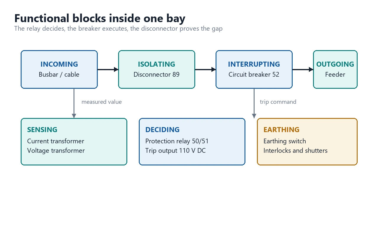
| Function group | Typical devices | What it does |
|---|---|---|
| Interrupting | Vacuum or SF6 circuit breaker, fuse | Breaks load current and fault current on command |
| Isolating | Disconnector, withdrawable truck, earthing switch | Creates a visible break and earths the isolated section |
| Sensing | Current transformer, voltage transformer | Scales primary quantities down to relay inputs |
| Deciding | Protection relay, trip unit | Detects abnormal conditions and issues the trip |
| Carrying | Main busbar, section busbar, risers | Distributes current between bays inside the enclosure |
| Supporting | Enclosure, cable chamber, arc duct, interlocks | Contains faults and sequences safe access |
Two items on that list do more work than their price suggests. Instrument transformers set the accuracy of everything downstream. A 10P20 current transformer keeps its composite error within 10 per cent at 20 times rated current, which is exactly the region where protection has to decide between trip and restraint. A 5P20 class is tighter, and at 24 kV the price difference is small enough that the tighter class usually wins.
The earthing switch does the job nothing else can. It applies the proven earth on the isolated section, and it is normally interlocked so the cable compartment door cannot open until the earth has been applied.
Voltage Classes: LV, MV and HV Compared
| Class | Voltage range | Typical application | Governing standard |
|---|---|---|---|
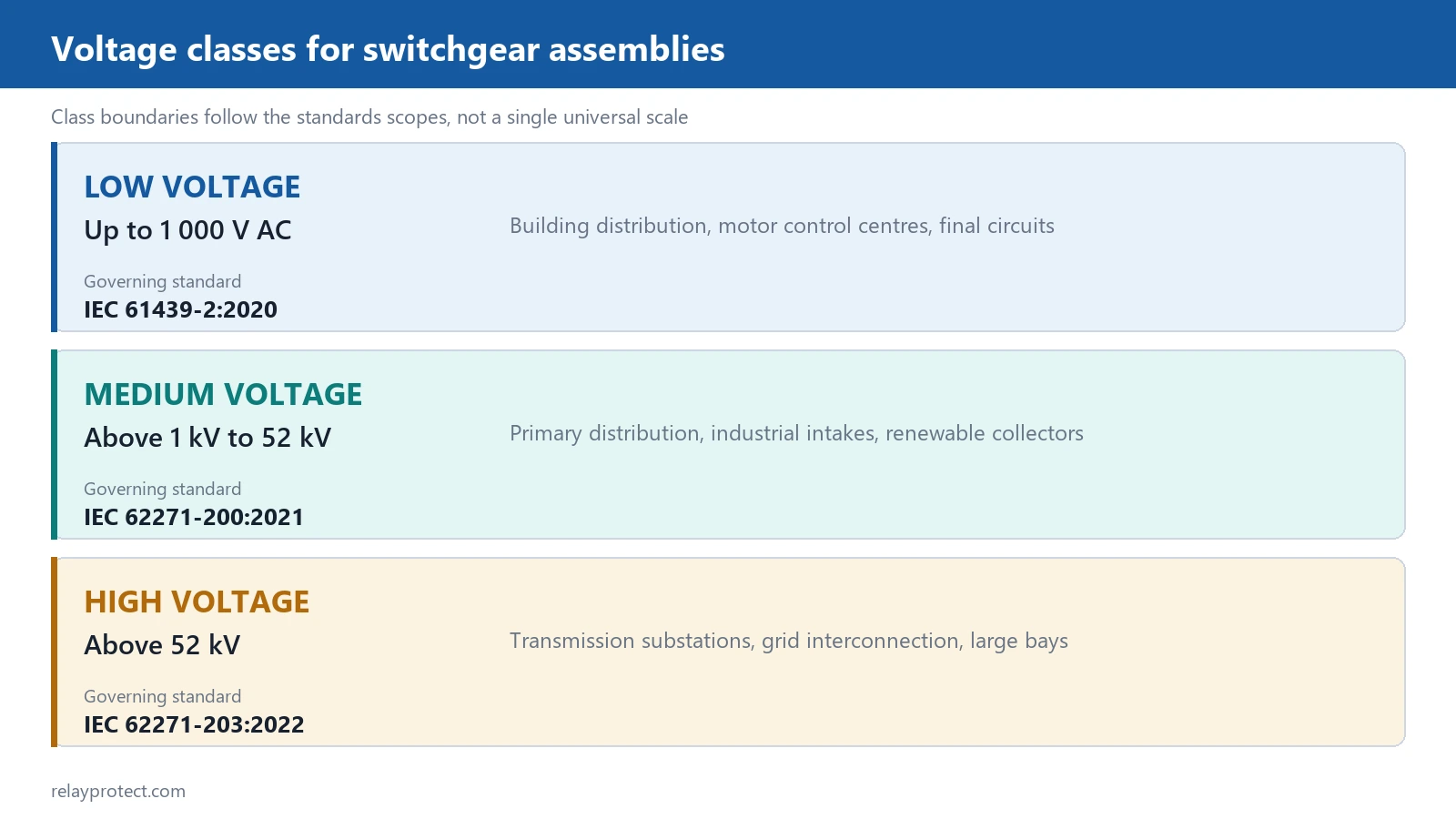
| Low voltage | Up to 1 000 V AC | Building distribution, motor control centres, final circuits | IEC 61439-2:2020 |
| Medium voltage | Above 1 kV to 52 kV | Primary distribution, industrial intakes, renewable collectors | IEC 62271-200:2021 |
| High voltage | Above 52 kV | Transmission substations, grid interconnection | IEC 62271-203:2022 |
The bands are conventions, not laws. IEC calls everything above 1 kV high voltage, so IEC 62271-200:2021 carries the words in its own title even though most engineers describe the equipment as medium voltage. IEEE C37.20.2-2025 covers metal-clad assemblies with rated maximum voltages from 4.76 kV to 48.3 kV, which is the same territory under a different name.
Convention matters less than the rating.
Specify by rated maximum voltage, never by nominal system voltage. A 12 kV rated breaker on an 11 kV system gives the margin the standard assumes. A 12 kV rated breaker on a 12 kV nominal system does not.
Pad-Mounted Switch Gear for Outdoor Distribution
Pad-mounted switch gear is the ground-level box standing on a concrete pad in a residential estate, feeding underground cables out to pad-mounted transformers. It is dead-front, tamper-resistant and operated from the front with a hot stick, because there is no fence and no room to swing a door into a live compartment. The whole point is that the public walks past it all day and nothing they can reach is live.

| Way | Usual device | What it actually protects |
|---|---|---|
| Incoming way | Load-interrupter switch | Nothing; it isolates a loop section so the rest can be restored |
| Fused way | Load-interrupter switch plus fuse | The transformer on a tap, not the loop cable |
| Tap way | Switch or fault interrupter | A single transformer, sized against its inrush |
| Main bus | 600 A busbar | Carries the loop current through the pad at continuous rating |
IEEE C37.74-2025 sets the requirements for these assemblies up to 38 kV rated maximum voltage, covering subsurface, vault and pad-mounted load-interrupter and fused load-interrupter designs. Typical ratings run 15.5, 27 or 38 kV class on a 600 A bus, with fault closing of 10 to 12.5 kA for the momentary duty.
Two field mistakes repeat. The first is sizing the fuse to the cable ampacity rather than to the transformer’s inrush and through-fault curve, which produces a unit that either blows on energisation or fails to clear a winding fault. The second is calling a normally open loop a dual supply. Until someone drives out and closes the tie, half the customers on that loop have one path and no spare.
Air-Insulated Versus Gas-Insulated Designs
| Aspect | Air-insulated | Gas-insulated |
|---|---|---|
| Primary insulation | Air clearances plus support insulators | Sealed compartments filled with insulating gas |
| Typical footprint | Large, set by clearance distances | Roughly one third of the air-insulated area at 145 kV |
| Inspection | Primary parts visible once the panels open | Sealed; condition read from gas density and partial discharge |
| Environment | Dust, humidity, salt and vermin all matter | The enclosure carries the environmental load |
| End of life | Components separable and mostly recyclable | Condition monitoring carries the whole burden |
Gas insulation wins on footprint, not on price. A sealed system also removes the pollution and condensation problems that dominate air-insulated maintenance schedules in coastal and desert plants.
The trade-off arrives at the end of the service life. A sealed compartment cannot be opened for a visual check, so condition monitoring carries the entire burden. Gas density, partial discharge and operating-time trending become the inspection regime, and they need instrumentation from day one.

Interrupting Media: Vacuum, SF6, Air and Oil
| Medium | Usual range | How the arc dies | Field notes |
|---|---|---|---|
| Vacuum | Up to 40.5 kV | Metal vapour condenses on the shield within microseconds | Dominant at medium voltage; the interrupter is a sealed bottle |
| SF6 | 12 kV to 800 kV | Electronegative gas captures electrons as current passes zero | Compact at high voltage; sealed-for-life designs are common |
| Air | Up to 1 kV | An arc chute splits and cools the arc | Standard for moulded-case and air circuit breakers |
| Oil | Legacy installations | Oil decomposes into hydrogen, which cools the arc | Rarely specified now; sampling and disposal are costly |
Vacuum wins on maintenance.
Vacuum took over the medium-voltage market for one practical reason. The interrupter is a sealed ceramic bottle with no gas to top up and no oil to sample. Contact erosion is measurable with a resistance check and a travel trace, and neither requires opening the bottle.
SF6 still holds the high-voltage end, where its dielectric strength lets a 145 kV bay fit inside a building that would otherwise need an outdoor compound. Handling rules are strict. Gas inventory records form part of the environmental permit in most jurisdictions, and leak detection is a permanent duty, not a commissioning formality.
Internal Arc Classification and Testing
| Framework | Designation | Protected side |
|---|---|---|
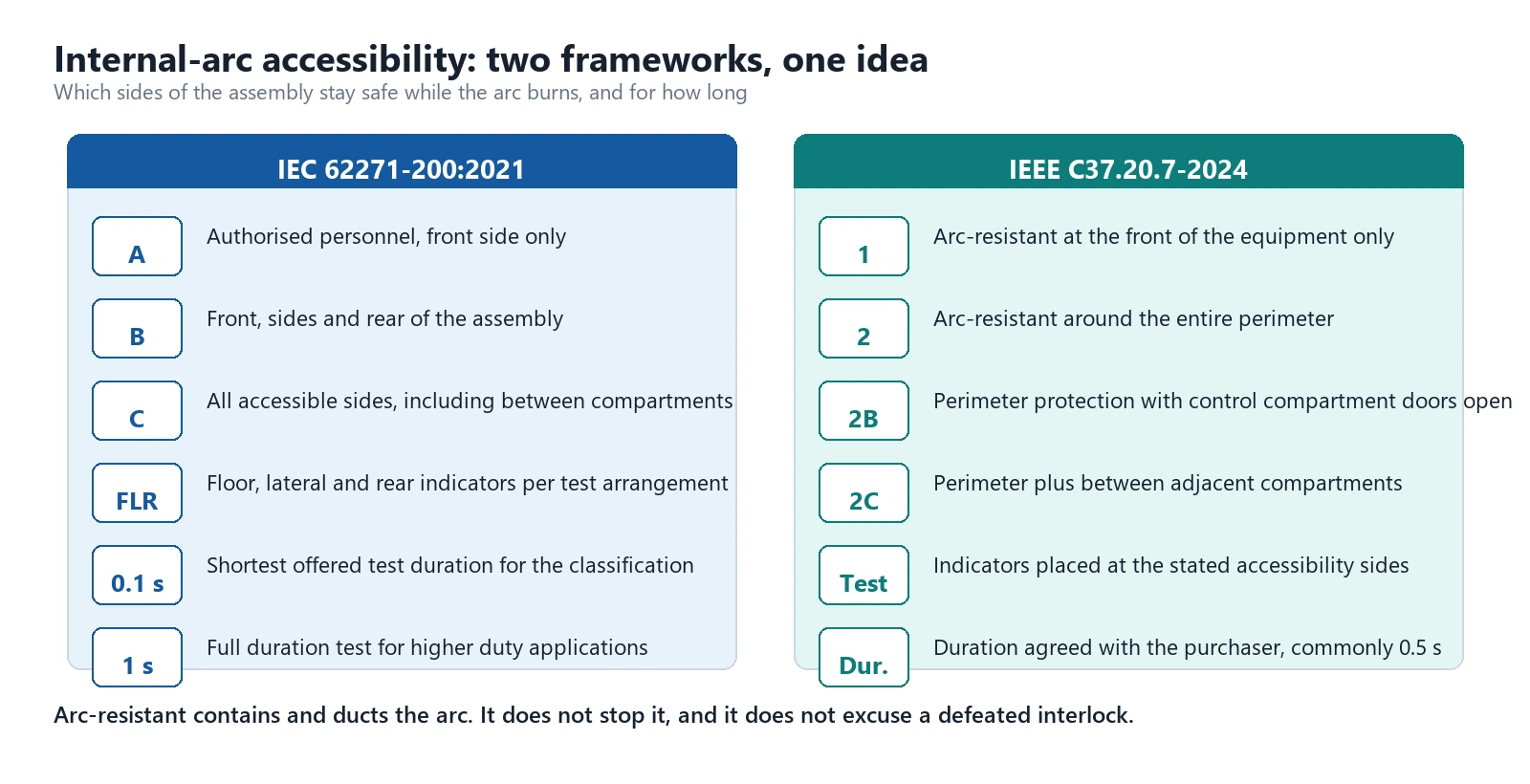
| IEC 62271-200:2021 | A | Authorised personnel, front side only |
| IEC 62271-200:2021 | B | Front, sides and rear of the assembly |
| IEC 62271-200:2021 | C | All accessible sides, including between compartments |
| IEEE C37.20.7-2024 | Type 1 | Front of the equipment only |
| IEEE C37.20.7-2024 | Type 2 | The entire perimeter |
| IEEE C37.20.7-2024 | Type 2B | Whole perimeter with the control compartment doors open |
| IEEE C37.20.7-2024 | Type 2C | Perimeter plus between adjacent compartments |
An internal arc is the worst event an assembly ever faces. Pressure rises within milliseconds, and it rises hardest in the compartment where the fault started. Arc-resistant designs do not stop the arc. They duct the hot gas out through a plenum to a place where nobody stands, and they keep doors and covers closed while they do it.
The distinction people miss: arc-resistant is not arc-proof. A Type 2B assembly protects a person standing at the front with the instrument door open. It does not protect anyone who has defeated an interlock to reach inside.
IEEE C37.20.7-2024 sets the test method and the accessibility types for North American practice. IEC 62271-200:2021 sets the internal-arc test and the IAC designation in its annex, with test durations of 0.1 s and 1 s offered to suit different protection schemes.
Protection, Metering and Control in the Cubicle
Modern medium-voltage practice puts the protection relay on the compartment door and the breaker behind it. The relay reads its current transformer secondaries, runs the protection elements, and drives the trip coil from a 110 V or 220 V DC auxiliary supply. Hardwired tripping paths stay independent of any PLC or RTU in the automation layer, and most users insist on that independence.
A feeder bay normally carries a time-delay overcurrent element plus the instantaneous companion, so that downstream fuses clear first and the bus stays in service:
- Phase and earth overcurrent elements, ANSI 50/51 and 50N/51N.
- A directional element where the network can back-feed the fault.
- An auto-reclose function on overhead distribution circuits, delayed so that transformer inrush after the reclose does not re-trip the feeder.
- Metering for current, voltage, power, energy and power factor.
- Event and disturbance recording for post-fault analysis.
Breaker failure protection is the function most often left out of a budget build. If the breaker does not open when commanded, the next upstream device must clear the fault instead, and on a bus that usually means a busbar differential scheme. That adds a 150 ms to 300 ms delay during which the busbar keeps feeding the fault, which is exactly why a 1 s short-time withstand is specified rather than 0.5 s.
Switch Gears: Plurals, Spelling and Drawing Conventions
Both spellings name the same equipment. Switch gear as two words is the older form and the one most searches still use; switchgear as one word is what the standards print. The plural appears in search boxes and in procurement documents from several markets and means the same thing again. Pick one spelling for anything you publish, and treat all three forms as one term when you read an enquiry.
On single-line diagrams, ANSI/IEEE C37.2-2022 fixes the device function numbers. Device 52 is an AC circuit breaker. Device 89 is a line switch or disconnector. Device 27 and 59 are undervoltage and overvoltage. Those numbers keep a drawing readable when the panel builder, the consultant and the operator sit in three countries, and they cost nothing to adopt.
Two sibling guides carry the next level of detail. The circuit breaker guide covers the interrupting device on its own, and the relay guide covers the device that issues the trip command.
Nine Ratings That Decide an Order
Nine numbers decide whether an assembly fits, and all of them have to be fixed before the drawings go out.
- Rated maximum voltage, in kV.
- Rated normal current of the busbar and of each feeder, in A.
- Rated short-time withstand current, usually for 1 s or 3 s, in kA.
- Rated peak withstand current, in kA peak.
- Rated short-circuit breaking current, in kA.
- Rated frequency, 50 Hz or 60 Hz.
- Internal-arc classification and its test duration.
- Degree of protection, typically IP4X indoors and IP54 outdoors.
- Loss of service continuity category, LSC1 or LSC2.
The one procurement teams get wrong is short-time withstand. A 630 A busbar may still have to carry 25 kA for a second or three if the upstream protection takes that long to decide. Rated normal current says nothing about that ability, and the two ratings come from different tests.
Also write the site conditions into the enquiry. IEC 62271-1:2017 defines normal service conditions as up to 1 000 m altitude and 40 °C ambient. Above either, derating applies, and agreeing derating at quotation stage costs a fraction of what it costs at factory acceptance testing.
Withdrawable Versus Fixed Breakers
A withdrawable truck lets one person roll a breaker out to a test position and then to a disconnected position without touching a busbar. Maintenance takes minutes instead of a shift, and a single spare truck can cover every bay of the same rating on the board.
Fixed breakers cost less and occupy less room. They suit installations where an outage window is arranged anyway, or where an upstream device can isolate the whole board for the duration of the work.
The risk specific to withdrawable designs is the shutter. Once the truck rolls out, shutters should close over the fixed contacts. Interlocks must prevent racking a closed breaker in or out of service, and they must prevent closing into a fault while the truck sits between positions. Check all three during commissioning, not on the datasheet.
Earthing Switches, Interlocks and Safe Isolation
Isolation is what makes maintenance possible, and it is where most incidents start. The sequence is fixed for a reason.
A working isolation has four steps: open the breaker, rack it to the disconnected position, close the earthing switch, then prove dead with a tester that has itself been proved on a live source immediately before and immediately after the check.
Do not improvise the sequence.
Interlocks exist because people skip steps under time pressure. Key interlocks, solenoid locks on the truck mechanism and mechanical shutters are the three common layers, and they are cheap against the alternative.
When Switchgear Is the Wrong Answer
Four boundaries where a full assembly is the wrong purchase:
- Small single-motor loads. A motor control centre built to the IEC 60947 series does the job for a fraction of the cost. Above-1-kV hardware only becomes competitive when the motor rating or the fault level forces it.
- Low fault level, protected upstream. A fused switch or a load-break switch may be all the installation needs. Paying for breaking capacity that the source can never deliver buys nothing.
- Easy space and access. Air-insulated construction is usually cheaper across a 25-year life in a greenfield yard. Gas insulation earns its premium in tight urban plots and harsh environments, not in open space.
- Frequent remote re-energisation. A contactor rated for hundreds of thousands of load operations beats a breaker rated for tens of fault operations. Pick the endurance class that matches the switching duty.
Commissioning and Maintenance Checks
Eight checks with the panels open, before the first energisation:
- Torque every bolted busbar joint to the value on the drawing, then mark it.
- Check protection settings against the approved coordination study, not against the last job.
- Primary-inject each current transformer circuit and confirm the relay reads the same value.
- Trip each breaker from the relay, from the local pushbutton and from the remote point.
- Verify every interlock by trying to defeat it.
- Confirm the trip coil operates at 70 per cent of nominal DC voltage.
- Record the insulation resistance of each circuit and keep the reading for trending.
- Record the mechanism travel and timing trace as the baseline for later comparison.
Four items then run on an annual or condition-based cycle: thermography of joints under load, a review of operation counters against the endurance rating, gas density checks on sealed systems, and a functional test of the complete trip path including the DC supply.
Conclusion
Switch gear is defined by function rather than by size, and that is the one idea worth carrying away. Five jobs: switch, protect, isolate, measure, control. An assembly that does all five qualifies, whatever voltage it runs at.
From there the decisions are practical. Fix the rated maximum voltage, the short-time withstand and the internal-arc class together, because they interact. Choose the interrupting medium to match the voltage and the maintenance regime the site can actually deliver. Then write the required type-test reports into the enquiry, so what arrives is what was tested.
Frequently asked questions
What does switch gear cover?
The term covers a coordinated set of switching devices, protective devices, measuring instruments and control equipment used to control, protect and isolate electrical circuits. Its reach runs from a low-voltage distribution board to a gas-insulated high-voltage bay.
What does an assembly do in a substation?
It receives power from a transformer or a line, distributes it to feeders, and clears faults on those feeders. It also provides the isolation points that let maintenance crews work on a de-energised section while the rest of the substation stays in service.
What is the difference between an assembly and a switchboard?
A switchboard distributes power but its devices are not tested to the same fault-clearing duties. An assembly that carries circuit breakers with a rated short-circuit breaking current and a published internal-arc classification meets a heavier test regime, and that difference shows up in the type-test report.
How long does the equipment last?
Thirty to forty years is a realistic design life for metal-enclosed assemblies. The limiting factor is rarely the enclosure. It is the operating mechanism and the secondary devices, which is why operation counters and timing traces are trended rather than checked once.
How often does it need maintenance?
Condition-based intervals beat fixed ones. As a floor, an annual thermographic survey under load plus a functional test of the trip path, with a full mechanical and electrical inspection every five to eight years or after a specified number of fault operations.
Is SF6 being phased out?
For new medium-voltage designs, vacuum has already replaced most SF6 applications, and several markets restrict SF6 inventory. At high voltage the gas remains common because no alternative yet matches its dielectric performance, so handling and leak-management rules continue to tighten instead.
What does IAC classification mean?
IAC is the internal-arc classification in IEC 62271-200:2021. It states which sides of the assembly were tested with an internal arc and for how long, so a Type B, 1 s rating protects personnel at the front, sides and rear for a full second of arcing.
How do I choose between air and gas insulation?
Choose on footprint pressure and on the inspection regime the site can deliver. Air-insulated construction suits yards with space and a maintenance crew. Gas-insulated construction suits confined urban plots, offshore platforms and harsh environments where the sealed enclosure removes the pollution problem.
Related reading
- Circuit breaker, which covers the interrupting device on its own.
- Relay, covering the device that issues the trip command.
- Substation, on where the assembly sits in the wider layout.
- How to Choose a Protection Relay for a Medium Voltage Substation, for settings and selection on the deciding side.
- ADW6800 controller for the automation layer.
Field record
The switchgear we supply sits in front of protection relays from 6 kV to 154 kV: ring main units at 11 kV in Nepal, the UAE and Malaysia; 22-35 kV in Laos, Cambodia and Thailand; 33 kV in Nigeria, Ghana and Turkey; 66 kV in Qatar; and 110 kV in Myanmar, Russia and Saudi Arabia. Above 35 kV the busbar and CT arrangement drives the relay selection, not the other way round. Every project above is listed in the country table.
Sources and standards
| Source | Standard | Edition | What it covers |
|---|---|---|---|
| IEC | IEC 62271-200 | 2021 | AC metal-enclosed assemblies above 1 kV up to 52 kV, including the internal-arc annex |
| IEC | IEC 62271-100 | 2021 | AC circuit-breakers above 1 000 V and their making and breaking tests |
| IEC | IEC 62271-1 | 2017 | Common specifications and normal service conditions for the series |
| IEC | IEC 62271-203 | 2022 | Gas-insulated metal-enclosed assemblies above 52 kV |
| IEC | IEC 62271-102 | 2018 | AC disconnectors and earthing switches |
| IEC | IEC 61439-2 | 2020 | Low-voltage power switchgear and controlgear assemblies |
| IEC | IEC 60255-1 | 2022 | Common requirements and tests for measuring relays |
| IEEE | IEEE C37.20.2 | 2025 | Metal-clad assemblies from 4.76 kV to 48.3 kV |
| IEEE | IEEE C37.20.7 | 2024 | Testing equipment up to 52 kV for internal arcing faults |
| IEEE | IEEE C37.74 | 2025 | Subsurface, vault and pad-mounted load-interrupter switchgear up to 38 kV |
| IEEE | IEEE C37.2 | 2022 | Device function numbers used on diagrams |
| IEEE | IEEE 1584 | 2018 | Arc-flash hazard calculation for the downstream risk assessment |
Primary documents are listed on the IEEE standards page for C37.20.7, and IEC publications are available through national committees. For the recording side of the same events, see the digital fault recorder selection guide.
Related: Substation Auxiliary Equipment
Related: Switches and relays
For a model recommendation, send the system voltage and the load details to our engineering team.
About Author

Hello, I'm Leon Zhang. I have 15 years of experience in the power relay protection industry with extensive pre-sales and after-sales project experience. Our company specializes in various complete sets of relay protection and automation equipment. I can assist customers in solving all practical on-site project challenges and provide optimal integrated solutions.
Tell Us Your Requirement



High Quality
Stable performance, reliable design, ensuring safe operation for power system protection and grid stability.
Fast Delivery
Timely delivery to support your urgent orders and project schedules efficiently and professionally at any time.
Best Warranty
Professional Warranty: Reliable after-sales support for stable relay protection and long-term customer satisfaction.