

-
Leon Zhang sales consultant
-
Email: zxl635973785@gmail.com
-
Phone/WhatsApp: +86 13655813266
Custom Locked Rotor Protection Relay | Factory Direct Supply & Technical Support
Industrial motors are the backbone of mining, oil & gas, water treatment, and manufacturing facilities. A locked rotor fault is one of the most destructive and common motor failures, causing sudden winding burnout, unplanned downtime, and even fire risks without reliable protection. Locked rotor protection is a dedicated motor protection function designed to detect stalled motor conditions during startup and instant dangerous overcurrent, safeguarding motor assets and continuous plant operation.
This guide delivers practical, field-verified knowledge of locked rotor protection, including working principles, standard ANSI 48 settings, calculation examples, testing procedures, troubleshooting, and relay selection tips for EPC contractors, plant electrical engineers, and industrial procurement teams.
What is Locked Rotor Protection for motor?
Definition of Locked Rotor Protection
Locked rotor protection is a core motor protection function that identifies a zero-speed rotor condition when a motor receives a starting command. When the rotor fails to rotate, the motor draws sustained 6–8 times full-load rated current, generating extreme internal heat in windings within seconds.
Unlike general overcurrent protection, ANSI 48 locked rotor protection targets startup-stage stall faults exclusively. It distinguishes normal short-duration starting inrush current from harmful sustained locked rotor current, avoiding nuisance tripping while cutting off power before permanent motor damage occurs.
Many industry practitioners confuse locked rotor protection with stall protection. The key difference lies in the fault occurrence stage, detection logic, and applicable scenarios, which we elaborate on in a dedicated comparison section below.
What Causes a Locked Rotor?
Locked rotor faults occur exclusively during motor startup, triggered by mechanical blockage or load abnormality. The most common field causes include:
- Mechanical jam: Misaligned couplings, broken transmission parts, or stuck mechanical components
- Bearing failure: Seized bearings due to insufficient lubrication, wear, or overheating
- Process blockage: Clogged pump impellers, blocked crusher cavities, or jammed conveyor belts
- Overloaded startup: Forced startup with excessive pre-loaded mechanical torque
- Foreign object intrusion: Debris entering motor internal gaps or equipment working chambers
- Motor startup failure: Stator winding phase loss, voltage imbalance, or incorrect wiring leading to startup stall
Locked Rotor Protection ansi code
Two ANSI standard codes are commonly adopted for motor locked rotor protection: ANSI 48 and ANSI 51LR. Plenty of electrical engineers tend to confuse these two codes. Although both can be utilized to implement motor locked rotor protection, they operate based on distinct working principles.
| Item | ANSI 48 | ANSI 51LR |
|---|---|---|
| Name | Locked Rotor / Incomplete Sequence | Locked Rotor Overcurrent |
| Chinese Name | Locked Rotor Protection / Failed Start Protection | Locked Rotor Overcurrent Protection |
| Detection Method | Startup duration, rotating speed and full startup process monitoring | Current measurement |
| Judgment Criterion | Whether the motor completes startup within the specified time | Whether the current exceeds the set value for a continuous period |
| Typical Application | Motor startup failure | Locked rotor during normal operation |
| Corresponding IEC Standard | Failed Start Protection | Locked Rotor Overcurrent Protection |
Why Is Locked Rotor Protection Important?
A locked rotor fault is a high-risk, fast-deteriorating failure. Without effective motor locked rotor protection, sustained overcurrent will cause irreversible damage within 2–10 seconds, depending on motor size and thermal withstand capability.
The direct consequences of missing or misconfigured ANSI 48 protection include:
- Rapid winding overheating and insulation breakdown
- Permanent winding burnout and motor scrapping
- Frequent unplanned production downtime
- Secondary equipment damage linked to the motor system
- Electrical short circuits and potential fire hazards
The standard fault response workflow of locked rotor protection is as follows:
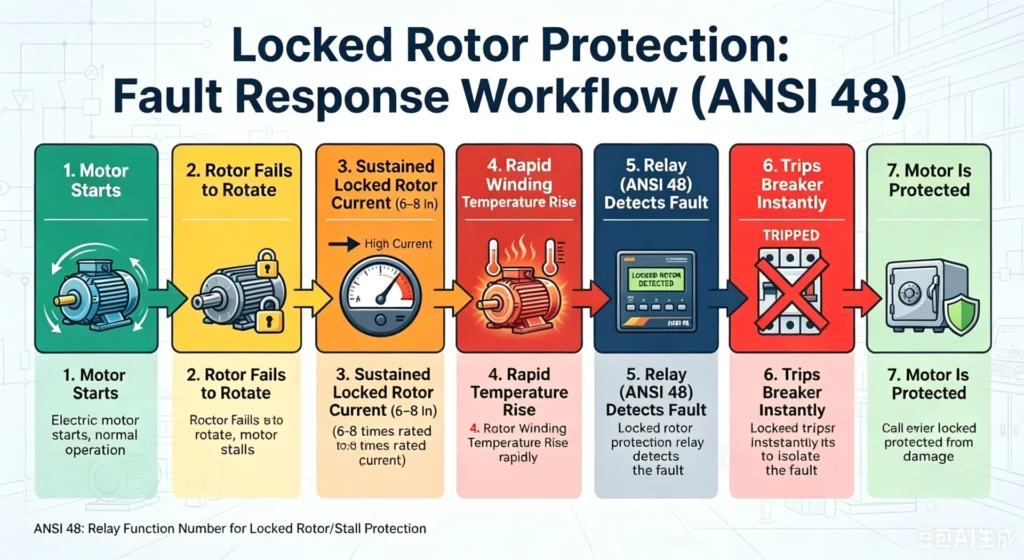
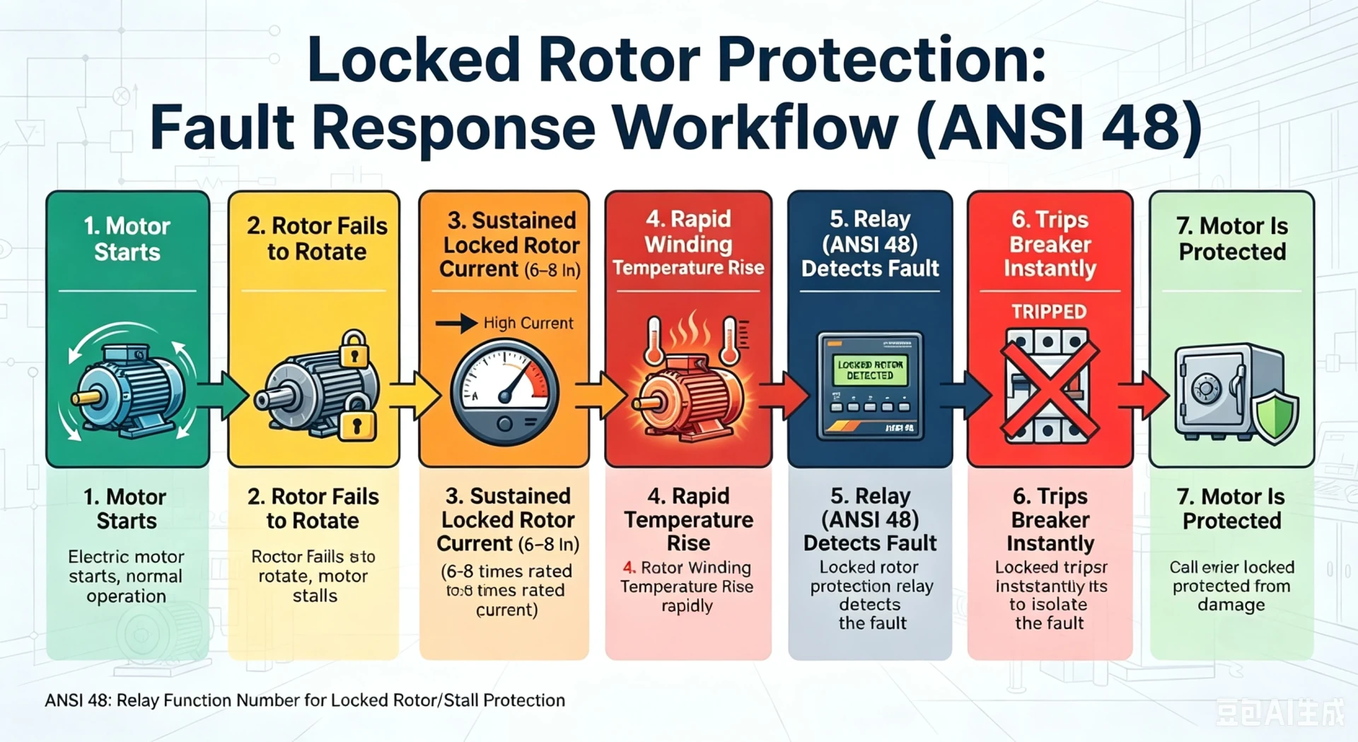
Motor Starts → Rotor Fails to Rotate → Sustained Locked Rotor Current (6–8 In) → Rapid Winding Temperature Rise → Relay (ANSI 48) Detects Fault → Trips Breaker Instantly → Motor Is Protected
How Does Locked Rotor Protection Work?
Motor locked rotor protection relay operates based on two core detection logics: overcurrent magnitude judgment and time-delay discrimination. It accurately filters normal motor starting inrush and captures true locked rotor faults.
Current Detection Logic
The relay collects real-time three-phase motor current via matched Current Transformers (CTs). Normal motor starting inrush current reaches 6–8 times rated current but lasts only 0.5–3 seconds for most standard loads. A locked rotor fault maintains this high current continuously without speed rise.
The protection system identifies fault characteristics by monitoring sustained overcurrent, rather than instantaneous peak current, to avoid misoperation on normal startup inrush.
Time Delay Logic
Time delay is the key to reliable locked rotor protection. Every motor has a safe startup time to overcome load inertia. Immediate tripping on high starting current will cause severe nuisance tripping.
Modern motor protection relays adopt two mainstream delay modes:
- Fixed definite time delay: Suitable for constant-load equipment (pumps, fans) with stable startup time
- Thermal model adaptive delay: Calculates real-time motor heat accumulation based on I²t curves, applicable for variable-inertia loads (crushers, conveyors)
Locked Rotor Protection Core Principle
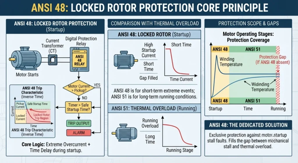
ANSI 48 is the industry-standard functional code for locked rotor protection, exclusively used for motor startup stall fault protection. Its core logic is simple and precise: if motor current exceeds the preset pickup value and lasts longer than the safe startup time, the relay triggers a trip or alarm.
Unlike ANSI 51 thermal overload protection (for running-stage overheating), ANSI 48 focuses on short-term extreme overcurrent during startup, filling the protection gap for motor startup faults.
Locked Rotor Protection Relay Settings
Proper locked rotor protection setting determines protection accuracy. Improper parameters are the main cause of nuisance tripping or failure to trip. Below are field-verified setting rules and practical calculation cases for industrial applications.
Locked Rotor Current Pickup Setting
The standard pickup current range is 5–7 × motor rated current (In), adjusted according to load types to match actual startup characteristics:
- Pumps & Fans: 5.0–5.5 In (low inertia, short startup time)
- Compressors: 5.5–6.0 In (medium load torque)
- Conveyors: 6.0–6.5 In (high starting inertia)
- Crushers & Heavy-duty equipment: 6.5–7.0 In (maximum startup resistance)
The pickup value must be higher than the motor’s normal maximum starting current to avoid nuisance tripping and lower than the minimum locked rotor current to ensure fault capture.
Locked Rotor Time Delay Setting
The time delay is determined by the motor’s safe stall withstand time, which is subject to motor manufacturer datasheets and field test data. General industry guidelines:
- Small low-voltage motors (<50kW): 2–3 seconds
- Medium-voltage motors (50–200kW): 3–5 seconds
- High-inertia load motors (crushers, large fans): 5–8 seconds
Key Note: Never set the delay longer than the motor’s thermal withstand time, otherwise winding burnout will occur before protection action.
Typical Locked Rotor Protection Setting Calculation Example
Motor Parameters: 400V, 160kW, Rated Current (In) = 290A, DOL starting, crusher load (high inertia)
Step 1: Current Pickup Calculation Apply heavy-load setting standard: 6.5 × In Pickup Current = 6.5 × 290A = 1885A
Step 2: Time Delay Setting Motor datasheet safe stall time = 6s Actual setting reserved margin = 5.5s
Final ANSI 48 Logic: Trip immediately when current ≥1885A and duration ≥5.5s; send pre-alarm at 80% threshold for early warning.
Locked Rotor Protection vs Stall Protection
These two protections are frequently confused in industrial debugging. The following table clarifies their core differences for accurate configuration:
| Comparison Item | Locked Rotor Protection (ANSI 48) | Stall Protection (ANSI 51/Thermal) |
|---|---|---|
| Detection Stage | Motor startup stage only | Motor running stage only |
| Rotor Speed | Zero speed (completely stuck) | Ultra-low speed (partial stall) |
| Current Level | 6–8 × rated current (extreme high) | 1.2–3 × rated current (moderate high) |
| ANSI Standard Code | 48 | 51 / 49 (thermal overload) |
| Typical Fault Cause | Startup blockage, mechanical jamming | Running overload, sudden load jamming |
| Protection Purpose | Prevent instantaneous startup burnout | Prevent long-term overheating damage |
How to Test Locked Rotor Protection?
Regular testing ensures ANSI 48 protection works reliably under actual fault conditions. Three standard test methods are widely adopted in factory FAT and on-site commissioning:
Secondary Injection Test (Laboratory & Routine Test)
This is the most common and safe test method for relay calibration. Use a professional relay test set to inject simulated locked rotor overcurrent into the relay:
- Inject preset pickup current (e.g., 1885A equivalent secondary current)
- Maintain current longer than setting delay
- Verify relay alarm, trip output, and fault record
Applicable for factory testing, periodic maintenance, and parameter verification.
Primary Injection Test (On-Site Commissioning)
Inject high current directly into the primary motor circuit to simulate real locked rotor faults. This test verifies the overall reliability of CTs, wiring, and the whole protection loop.
Safety Note: Must be performed by certified electrical engineers with power cut-off and safety isolation measures.
Functional Simulation Test
Simulate motor startup stall signals via relay built-in functions to verify threshold judgment, timing accuracy, and trip logic. No high current required, suitable for quick on-site functional verification.
Common Locked Rotor Protection Problems and Solutions
1. ANSI 48 trips frequently during normal motor startup
Causes: Current pickup value set too low; time delay shorter than actual startup time; high-inertia load with long acceleration time
Solutions: Increase pickup current appropriately; extend delay time according to actual startup duration; enable thermal model adaptive delay for inertia loads
2. Relay fails to trip on actual locked rotor fault
Causes: Incorrect CT ratio parameter; mismatched current setting; faulty CT wiring or signal loss
Solutions: Calibrate CT ratio and secondary circuit; recheck and reset ANSI 48 parameters; inspect wiring and eliminate signal faults
3. Long-term nuisance tripping in stable operation
Causes: Slight voltage fluctuation leads to minor current surge; aging motor with unstable startup current
Solutions: Optimize threshold margin; enable current fluctuation filtering function; match protection parameters with motor aging characteristics
Industrial Applications of Locked Rotor Protection
ANSI 48 locked rotor protection is a mandatory configuration for all medium and high-power industrial motors, widely applied in harsh and continuous-production industries:
- Energy & Power: Power plants, oil & gas facilities, petrochemical plants
- Heavy Industry: Mining, cement plants, steel mills, crushing systems
- Public Utilities: Water treatment plants, HVAC systems, pump stations
- Logistics & Manufacturing: Conveyor systems, compressor units, industrial fan equipment
These scenarios feature high load inertia, frequent startup, and strict continuous production requirements, making locked rotor protection critical to avoid massive production losses.
How to Choose a Qualified Locked Rotor Protection Relay
For EPC projects and plant renovation, a reliable locked rotor protection relay must integrate accurate ANSI 48 logic, multi-functional protection, and industrial stability. The core selection criteria are as follows:
Complete Protection Function Portfolio
Qualified motor relays must match full motor protection requirements, not only single ANSI 48 function:
- ANSI 48 locked rotor protection
- ANSI 49 thermal overload protection
- ANSI 46 phase unbalance/negative sequence protection
- ANSI 50/51 overcurrent protection, 50G/51G ground fault protection
Stable Communication & System Compatibility
Suitable for industrial SCADA and DCS system integration:
- Standard protocols: Modbus RTU, Modbus TCP, IEC 61850
- Real-time fault data upload and remote monitoring
Industrial-Grade Reliability
- Full EMC electromagnetic compatibility, anti-interference for harsh industrial sites
- Wide working temperature range (-20℃ ~ +70℃)
- IEC, CE certified, factory-tested quality
- Complete event recording and fault waveform capture
Low Maintenance Cost
- Intuitive LCD local display
- One-click parameter backup and restoration
- Real-time self-diagnosis of hardware and wiring faults
- Remote configuration and debugging support
Why Choose Our Motor Protection Relay Solutions
As a professional industrial motor protection relay manufacturer with over 10 years of overseas project experience, our solutions fully comply with IEC and ANSI industry standards, serving global EPC contractors, power engineering companies, and end-user plants.
Full-Coverage Product Portfolio
We provide tailored locked rotor protection relays for all scenarios: low-voltage, medium-voltage, and multifunctional integrated motor protection devices, covering 0.4kV–35kV motor systems to meet different project specifications.
Professional Technical Support
Our overseas technical team provides one-stop engineering services: protection parameter calculation and setting, system protection coordination optimization, wiring guidance, and on-site commissioning support. We solve on-site tripping, setting mismatch, and compatibility problems for clients in real time.
Strict Quality Assurance
All relays pass 100% factory functional testing, EMC anti-interference testing, and FAT factory acceptance testing. Complete official technical documents, test reports, and certification files are provided to support project bidding and acceptance.
Flexible Delivery & Global Service
We support fast batch delivery, OEM/ODM customized services, and long-term after-sales technical support. Our products have been widely applied in mining, chemical, water treatment, and power projects across Southeast Asia, Africa, the Middle East, and Europe, with stable field operation feedback.
Frequently Asked Questions
1. What is ANSI 48 protection?
ANSI 48 is the standard industry code for locked rotor protection, dedicated to detecting zero-speed startup stall faults of industrial motors, preventing winding burnout caused by sustained extreme overcurrent during motor startup.
2. What are the main causes of a locked rotor fault?
Locked rotor faults are mainly caused by mechanical jamming, bearing seizure, load blockage, foreign object intrusion, and failed motor startup, all leading to zero rotor speed and sustained high current.
3. How do you set locked rotor protection parameters?
Set current pickup at 5–7 times rated current based on load type; set time delay according to motor safe stall withstand time (2–8s). Avoid values exceeding the motor’s thermal tolerance range.
4. What is locked rotor current?
Locked rotor current refers to the sustained overcurrent generated when the motor rotor is stuck, typically 6–8 times the motor full-load rated current, which causes rapid winding heat accumulation.
5. What is the difference between locked rotor and stall protection?
Locked rotor protection (ANSI 48) acts on zero-speed startup faults; stall protection (ANSI 49/51) acts on low-speed overload faults during motor running. Their current thresholds and application stages are completely different.
6. How long should locked rotor protection delay be?
2–3s for small low-voltage motors, 3–5s for medium-voltage motors, 5–8s for high-inertia loads. The delay must be shorter than the motor’s datasheet-specified safe stall time.
7. Can VFD-driven motors use locked rotor protection?
Yes. VFD motors still face startup stall risks. Professional relays support adaptive ANSI 48 setting for VFD output characteristics to achieve accurate protection.
8. How to test ANSI 48 protection?
Main test methods include secondary injection calibration (routine test), primary injection test (on-site commissioning), and functional simulation test to verify trip threshold, timing, and fault response.
9. Which industries require locked rotor protection?
All industries with continuous-operation industrial motors, including mining, petrochemical, water treatment, power plants, cement, steel, and HVAC systems.
10. How to choose a qualified ANSI 48 motor protection relay?
Focus on standard ANSI 48 logic accuracy, complete supporting protection functions, industrial anti-interference capability, standard communication protocols, and professional after-sales commissioning support.
11: What is compressor motor locked rotor protection?
It is a dedicated motor protective function. When the compressor motor is energized yet the rotor fails to rotate due to jamming, this protection will quickly cut off power supply to avoid winding burnout caused by excessive locked-rotor current.
12: What purposes does fan locked rotor protection serve?
When the fan rotor locks up, the input current surges sharply. Continuous high current will overheat windings, damage insulation and burn out the entire fan motor. This protection safeguards the fan motor and extends its service life.
13: What is 51LR AC inverse time overcurrent locked rotor protection relay?
51LR is an ANSI standard designated relay function. It is an AC motor dedicated protective relay adopting inverse time overcurrent characteristic, mainly designed to detect locked rotor status of AC motors and implement rapid tripping protection.



About Author

Hello, I'm Leno Zhang. I have 15 years of experience in the power relay protection industry with extensive pre-sales and after-sales project experience. Our company specializes in various complete sets of relay protection and automation equipment. I can assist customers in solving all practical on-site project challenges and provide optimal integrated solutions.
Tell Us Your Requirement
High Quality
Stable performance, reliable design, ensuring safe operation for power system protection and grid stability.
Fast Delivery
Timely delivery to support your urgent orders and project schedules efficiently and professionally at any time.
Best Warranty
Professional Warranty: Reliable after-sales support for stable relay protection and long-term customer satisfaction.