

-
Leon Zhang sales consultant
-
Email: zxl635973785@gmail.com
-
Phone/WhatsApp: +86 13655813266
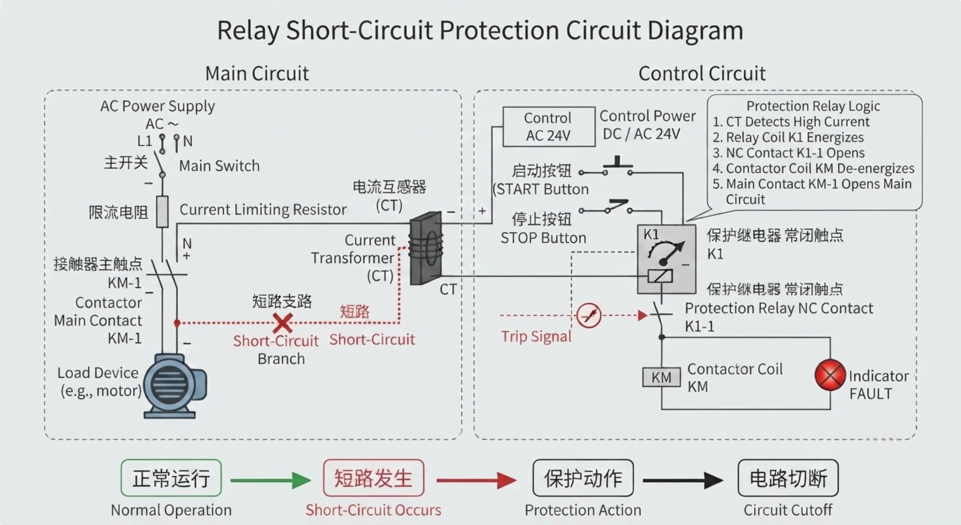
Short Circuit Protection Relay for Transformer Motor Distribution Substation System Wholesale Supply
Introduction
Short circuits rank among the most destructive electrical faults in power grids and industrial power distribution systems. In just a few milliseconds, a short circuit can surge fault current up to thousands of amperes. Without targeted and reliable protection measures, this extreme current will lead to irreversible insulation breakdown inside electrical devices, burnt transformer windings, overheated and melted power cables, even violent switchgear explosion and large-scale unplanned power outages that paralyze production and daily power supply.
As the core link of power system safety defense, a short circuit protection relay serves as an intelligent monitoring hub. It keeps tracking real-time electrical parameters on power loops, identifies abnormal overcurrent and short-circuit conditions accurately, and transmits trip commands to circuit breakers instantly to cut off faulty circuits. By isolating the fault area in the shortest possible time, it prevents fault escalation and safeguards the entire power system as well as valuable power assets.
A short circuit protection relay is one of the most important protection devices in modern electrical networks. It continuously monitors current and quickly isolates faulty sections to protect transformers, generators, motors, and power distribution systems.
What Is a Short Circuit Protection Relay?
Definition of Short Circuit Protection Relay
A short circuit protection relay is an intelligent electrical protection device designed specifically to detect excessive fault currents triggered by short-circuit failures and trigger circuit breaker tripping actions automatically. Widely deployed across core power scenarios, it is a standard configuration for:
- Urban and industrial substations
- Factory industrial power supply systems
- Solar, wind and other renewable energy power plants
- Long-distance power transmission and regional distribution networks
Main Protection Functions Related to Short Circuit Faults
Different types of short-circuit and abnormal current risks correspond to standardized protection functions with unified ANSI industry codes, covering all mainstream fault scenarios:
1. Overcurrent Protection Relay (ANSI 50/51)
Applicable objects: Power feeders, industrial motors, distribution and main power transformers
Core function: Judges when loop current exceeds the preset threshold value, and sends a trip signal to breakers after a set delay to avoid equipment damage caused by long-term overcurrent.
2. Instantaneous Overcurrent Protection (ANSI 50)
Core features: Ultra-fast action speed without intentional time delay
Application scenarios: Severe metallic short-circuit faults on busbars, outgoing feeders and transformer primary sides, which need immediate power cutoff to avoid equipment breakdown.
3. Time Overcurrent Protection (ANSI 51)
Core features: The relay’s tripping action time changes inversely with fault current; larger fault current leads to shorter delay time.
Core value: Realizes selective protection coordination between upper-level and lower-level protection devices, ensuring only the nearest faulty branch trips while the rest of the grid remains powered.
4. Earth Fault Protection (ANSI 50N/51N)
Target faults: Phase-to-ground short circuits, cable insulation aging and breakdown, poor equipment earthing faults. It captures residual grounding current to locate hidden insulation faults that regular overcurrent protection may miss.
How Does a Short Circuit Relay Work?
The short circuit protection relay cannot directly measure ultra-high primary current on high-voltage power lines. Instead, it relies on a complete signal collection, analysis and execution workflow to finish fault judgment and isolation.
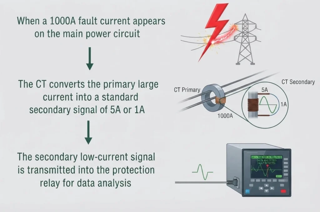
1. Fault Current Measurement
Current transformers (CT) are installed on primary power circuits to step down large system current into low-amplitude secondary signals that the relay can safely process.
Take a typical case:
2. Signal Processing and Fault Judgment
Modern numerical protection relays no longer rely on simple electromagnetic induction. They comprehensively calculate multiple electrical dimensions to eliminate misjudgment:
- Real-time current magnitude
- Loop voltage level
- Fault direction to distinguish forward and reverse faults
- Phase angle between voltage and current
- Lasting duration of abnormal current
The relay compares all measured parameters with pre-configured fixed values including pickup current threshold, tripping time delay and protection characteristic curves. Once the measured data exceeds the allowable range, the relay confirms a valid fault.
3. Trip Command Output
After confirming a short-circuit fault, the relay outputs a hard-wired trip signal directly to the circuit breaker’s tripping coil. The full protection action sequence is fixed and standardized:
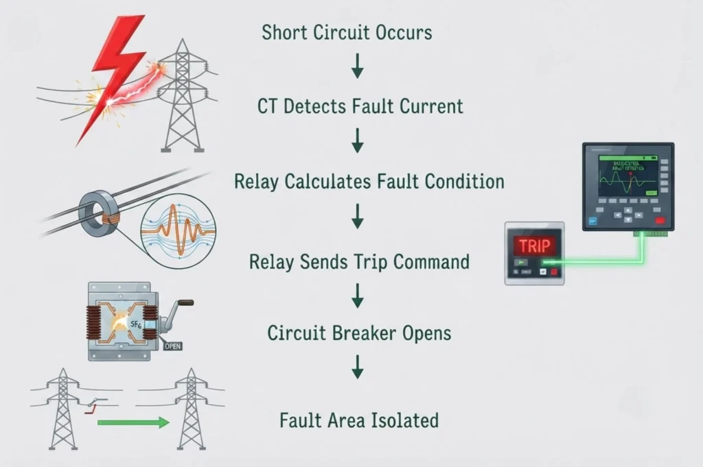
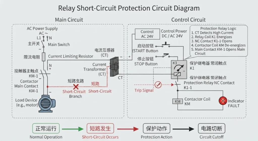
Short Circuit Protection using relay circuit diagram
What Happens If a Relay Is Shorted?
If the protection relay itself suffers an internal short circuit or hardware failure, it will lose its protection capability and even interfere with the stable operation of the whole power system, bringing four major hidden dangers:
1. False Tripping
Internal circuit short-circuit or component damage may make the relay send a false trip signal when no actual short-circuit fault exists. The direct consequences include unnecessary regional power outages, forced production line shutdown and decreased overall power supply reliability. For example, a faulty feeder protection relay may cut off normal power supply randomly without any equipment abnormality.
2. Failure to Protect Equipment
In the event of a real short circuit, a broken relay cannot output a trip instruction, so the dangerous fault current keeps circulating in the loop. This will burn transformer windings, cause cables to overheat and catch fire, and eventually lead to permanent scrapping of switchgear and core power equipment.
3. Permanent Relay Internal Damage
A short-circuit fault inside the relay often causes irreversible damage: burnt internal contact points, breakdown of circuit board electronic components, PCB board burnout and complete loss of communication connection with the background monitoring system.
4. Disordered Protection Coordination
Power grid protection relies on graded coordination between multiple relays. A faulty relay will break the selective protection logic, affect the backup protection linkage, and weaken the overall stability of the power grid against faults.
What Are the Symptoms of a Bad Relay?
Field maintenance staff can quickly judge relay failure through these obvious abnormal manifestations:
1. Unexpected Circuit Breaker Trips
Typical symptoms: The circuit breaker trips repeatedly and the system cuts power with no visible short circuit or overload fault.
Root causes: Incorrect parameter setting inside the relay, damaged output contact terminals or mainboard internal malfunction.
2. No Tripping Response During Actual Faults
Warning signs: Routine protection function test fails; power equipment heats up abnormally while the fault current is still connected to the circuit. This is the most dangerous fault mode of a protection relay.
3. On-device Alarm Indications
Intelligent numerical relays will pop up text or code alarms on the local display screen, including self-supervision alarm, relay main unit failure alarm, CT secondary circuit disconnection fault and background communication error reminder.
4. Abnormal Tripping Timing
Two common abnormal conditions: delayed tripping far beyond the preset delay time; instantaneous tripping without delay when the protection is supposed to act with a time limit. The main triggers are wrong parameter configuration, outdated firmware or aging internal electronic components.
How to Test If a Relay Is Blown?
A complete relay inspection follows five steps from simple visual check to professional function verification:
1. Visual Inspection
First carry out appearance inspection to check for obvious damage: burnt black marks on the shell or terminals, cracked wiring terminals, loose secondary wiring, metal corrosion and pungent burnt odor from internal components.
2. Check Relay Power Supply
Verify the auxiliary working power of the relay, which is mostly DC 24V, 48V, 110V or 220V. Confirm the input AC or DC voltage is within the rated range and all terminal wiring is tightly fastened without virtual connection.
3. Test Relay Coil Resistance
Use a multimeter to measure the resistance of the relay internal coil:
- Normal status: The multimeter shows a stable fixed resistance value
- Infinite resistance reading: The coil is open-circuited and broken
- Near-zero ultra-low resistance: The coil suffers an internal short circuit
4. Perform Secondary Injection Testing
This is the most authoritative professional detection method, which must adopt dedicated relay protection test equipment (secondary injection tester / relay test set). Standard test items cover:
- Action pickup current value
- Accurate tripping operation time
- Complete trip logic verification
- Protection characteristic curve fitting
- Upper computer communication function
5. Review Relay Event Records
Digital relays automatically store historical data including fault current magnitude, precise trip time, fault type and full waveform recording. Maintenance engineers can export these records to confirm whether the relay acts correctly, identify real fault causes and check the rationality of original protection settings.
How Do You Fix a Short Circuit Problem?
Follow this standardized troubleshooting and repair process to eliminate short-circuit faults safely and thoroughly:
Step 1: Disconnect and Isolate Power
Prioritize construction safety: cut off the upper-level power supply of the faulty loop strictly, implement lockout and tagout procedures to prevent accidental power transmission, and use a voltmeter to confirm zero residual voltage on the circuit before operation.
Step 2: Locate the Short Circuit Point
Carry out targeted inspection by category:
- Cable lines: Check for outer insulation damage, cable aging cracking and water immersion dampness
- Core equipment: Inspect motors, transformers and switchgear for internal short-circuit and burnout
- Control secondary loops: Troubleshoot relay wiring and terminal blocks for short-circuit between lines.
Step 3: Check Protection Relay Settings
Recheck all core configuration parameters of the relay: rated working current, CT transformation ratio, pickup current setting, time delay value and upper-lower level protection coordination parameters. Improper settings are the top cause of frequent nuisance tripping or delayed fault clearing.
Step 4: Repair or Replace Faulty Components
Corresponding solutions for different faults:
Replace the completely damaged protection relay; rewire and bind broken secondary cables; swap out failed current transformers; rectify unqualified earthing connections; modify and optimize protection setting parameters to match on-site operating conditions.
Can an Electrician Fix a Short Circuit?
The boundary of maintenance work is divided according to voltage level and system complexity:
Short Circuits an Electrician Can Usually Repair
Certified general electricians are competent for low-voltage and civil distribution faults: household circuit short-circuit issues, low-voltage wiring errors, damaged miniature circuit breakers and cable replacement work.
When a Protection Engineer Is Needed
For medium and high voltage power systems including 6.6kV, 11kV, 22kV, 33kV and 110kV substations, professional protection engineers must be assigned to complete follow-up work centered on relay short circuit protection: relay function testing, protection coordination scheme analysis, relay fixed value calculation and fault recording data analysis to avoid secondary system hidden dangers.
Applications of Short Circuit Protection Relays
1. Transformer Protection
Main protection functions: Differential protection (ANSI 87T), overcurrent protection (ANSI 50/51) and earth fault protection.
Applicable equipment: Distribution transformers, grid main power transformers and photovoltaic/wind power station step-up transformers.
2. Motor Protection
Focuses on three typical motor faults: internal phase-to-phase short circuit, locked rotor stall and long-term overload operation, realizing full-cycle protection for large and medium-sized industrial motors.
3. Generator Protection
Covers stator winding short-circuit protection, generator earth fault protection and backup overcurrent protection to guarantee the safe operation of synchronous generators in power plants.
4. Feeder Protection
Mainly deployed on outgoing feeders of substations, factory power distribution rooms, solar farms and wind power generation systems to protect transmission lines from short-circuit damage.
How to Select the Right Short Circuit Protection Relay?
Four core dimensions shall be taken into consideration during model selection:
1. Voltage Level
Confirm the application scenario: low-voltage distribution system, medium-voltage industrial power grid or high-voltage transmission network, and select relays with matching insulation grade and rated voltage.
2. Protection Requirements
Select functional modules as required: basic overcurrent protection, directional overcurrent for reverse power prevention, differential main protection for key equipment, or distance protection for long transmission lines.
3. Communication Protocol
Match the relay communication interface with the existing SCADA monitoring system. Common mainstream protocols include IEC 61850, Modbus TCP/RTU, IEC 60870-5-103 and DNP3.
4. Testing and Certification
Prioritize products complying with international IEC standards. Confirm the manufacturer provides complete factory inspection reports, relay calibration records and third-party protection performance type test certificates.
Why Choose Our Short Circuit Protection Relay Solutions?
Professional Technical Support
We deliver one-stop technical service: customized protection scheme design according to project conditions, accurate relay model selection guidance and on-site parameter setting remote support for global EPC and power grid clients.
Complete Protection Product Range
Our product portfolio covers all mainstream power protection devices: feeder line protection relay, transformer dedicated protection relay, motor comprehensive protection relay, generator protection unit and transmission line distance protection relay.
Strict Quality Assurance
Every unit undergoes full factory inspection before delivery, including precision relay calibration, all-item function testing and multi-protocol communication joint debugging, to ensure stable performance under harsh on-site grid conditions.
FAQ About Short Circuit Protection Relay
Q1: What is the purpose of a short circuit protection relay?
A short circuit protection relay detects abnormal overcurrent caused by short-circuit faults, outputs trip signals to circuit breakers to cut faulty circuits, and isolates damaged equipment to stop fault expansion in power systems.
Q2: Can a bad relay cause a breaker to trip?
Yes. Hardware failure or parameter disorder inside a faulty relay will generate false trip signals, leading to unnecessary power outages and production suspension.
Q3: How long does a short circuit protection relay take to operate?
Modern numerical protection relays can identify severe metallic short-circuit faults and complete tripping output within several milliseconds, achieving ultra-fast fault clearance.
Q4: What is the difference between a fuse and a protection relay?
表格
| Fuse | Protection Relay |
|---|---|
| Only simple one-time fusing protection | Multi-condition intelligent logic protection |
| Needs replacement after every action | Restorable and reusable after fault removal |
| No data upload and remote monitoring | Supports SCADA background data uploading and remote control |
Q5: How often should protection relays be tested?
Medium and high voltage protection relays require periodic calibration and function testing in accordance with local power industry specifications and enterprise maintenance management regulations, with a conventional inspection cycle ranging from 1 to 5 years.



About Author

Hello, I'm Leno Zhang. I have 15 years of experience in the power relay protection industry with extensive pre-sales and after-sales project experience. Our company specializes in various complete sets of relay protection and automation equipment. I can assist customers in solving all practical on-site project challenges and provide optimal integrated solutions.
Tell Us Your Requirement
High Quality
Stable performance, reliable design, ensuring safe operation for power system protection and grid stability.
Fast Delivery
Timely delivery to support your urgent orders and project schedules efficiently and professionally at any time.
Best Warranty
Professional Warranty: Reliable after-sales support for stable relay protection and long-term customer satisfaction.