

-
Leon Zhang sales consultant
-
Email: zxl635973785@gmail.com
-
Phone/WhatsApp: +86 13655813266
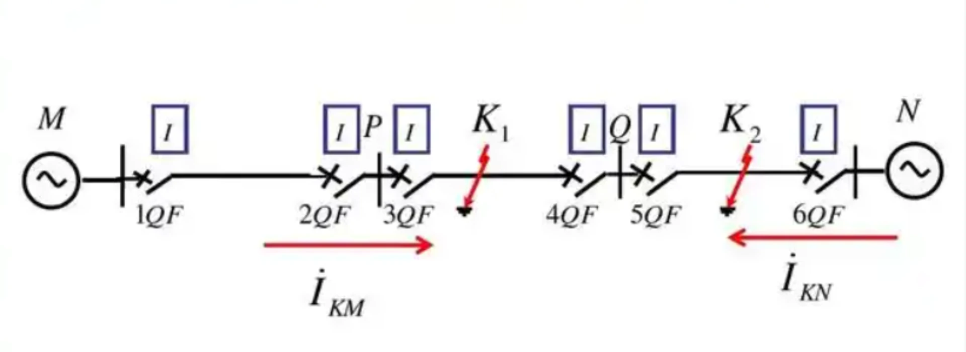
Directional Overcurrent Relay Protection | ANSI 67/67N
Directional overcurrent relay protection is the ANSI 67 function that adds a direction check to a 50/51 overcurrent stage. The relay compares fault current phase angle against a polarising voltage reference, so it trips only for faults flowing into the protected zone and blocks current flowing the other way. ANSI/IEEE C37.2-2022 defines function 67; IEC 60255-1:2022 governs the relay.
At a glance
Short answer: directional overcurrent relay protection turns a plain 50/51 stage into a selective scheme. The ANSI 67 directional overcurrent element decides which way the fault current flows before allowing a trip. Paired with ANSI 67N, the scheme covers both phase faults and earth faults on feeders where power can reverse.
- ANSI 67 covers directional phase overcurrent; ANSI 67N covers directional earth fault. Both sit on top of ANSI 50 instantaneous and ANSI 51 inverse-time stages.
- Direction is read from the phase angle between fault current and a polarising voltage: Vpx or Vpy for phase faults, residual or zero-sequence voltage for the 67N earth fault directional function.
- The characteristic angle, RCA, positions the forward operating region. Typical values are 30 to 45 degrees for phase faults and 0 or minus 45 degrees for earth faults.
- Apply directional overcurrent relay protection where fault current can reverse: ring mains, parallel feeders, dual supplies and distributed generation.
- A directional relay settings sheet must state element enable, polarisation choice, RCA, sector width and the blocking logic used against reverse current.
- Set pickup above maximum load current, then grade upstream against downstream so the relay nearest the fault clears first.
- Without a VT feed the directional element has no reference, and the feeder falls back to a plain 50/51 function.
- Prove the scheme with secondary injection from CT and VT, then confirm the trip path reaches the breaker trip coil.
Hardware for this duty is a directional overcurrent relay that keeps direction, polarisation and grading as separate setting groups. Directional overcurrent relay protection is then commissioned against IEC 60255-1:2022 type tests and ANSI/IEEE C37.2-2022 function numbers.
What Is Directional Overcurrent Relay Protection?
Directional overcurrent relay protection detects overcurrent and also determines the direction of fault current flow, distinguishing whether a fault is located inside or outside the protected zone.
How it works:
The relay obtains the current signal via a CT and the voltage reference via a VT, then compares the phase angle between them to determine fault direction:
- Forward fault → Issues a trip command to isolate the fault
- Reverse fault → Blocks tripping, allowing upstream or downstream protection to handle it
Applications:
- Looped networks, parallel feeders, multi-source networks
- Systems with distributed generation (solar, wind)
Corresponding standards:
- ANSI 67: Directional Phase Overcurrent Protection
- ANSI 67N: Directional Earth-Fault Protection
Core value: Ensures that only the faulty feeder trips, avoiding unnecessary outages in non-faulted sections, a key technology for minimizing outage areas and achieving selective protection.
How Does Directional Overcurrent Protection Work?
Directional overcurrent protection is a key function for distribution networks with multiple power sources or looped configurations. Unlike standard overcurrent protection, which only measures current magnitude, directional protection also determines the direction of fault current flow, ensuring that only the faulty section is tripped while the rest of the system remains online.
Below is the step-by-step logic sequence of how directional overcurrent protection operates.
The Directional Protection Workflow
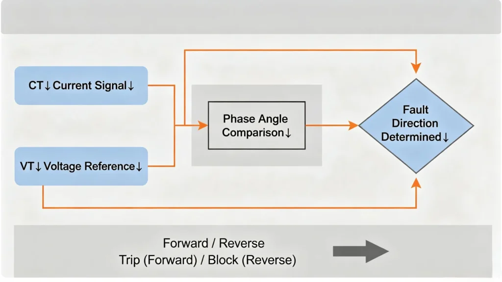
Step-by-Step Breakdown
Step 1: Current Signal (CT)
The Current Transformer (CT) steps down the primary current to a safe, measurable secondary value (e.g., 5A or 1A). This current signal is fed into the protection relay.
Step 2: Voltage Reference (VT)
The Voltage Transformer (VT) provides a voltage reference signal. This is essential because the relay needs to compare the phase angle between voltage and current to determine fault direction.
Step 3: Phase Angle Comparison
The relay measures the phase angle between the voltage reference and the fault current. This angle indicates the direction of power flow, which also sets the fault direction.
- In a forward fault, the fault current flows from the source into the protected zone.
- In a reverse fault, the fault current flows out of the protected zone.
Step 4: Forward / Reverse Decision
The relay compares the measured phase angle against a pre-set characteristic angle (also called Relay Characteristic Angle, RCA). This angle defines the relay’s operating zone, typically an 80° to 90° sector around the characteristic angle.
Step 5: Trip / Block
- Forward fault → The relay initiates a trip command to the circuit breaker, isolating the fault.
- Reverse fault → The relay blocks tripping, allowing upstream or downstream protection to handle the fault instead.
Key Protection Functions
ANSI 67: Directional Phase Overcurrent
What it does:
Detects overcurrent and determines whether the fault current is flowing forward (into the protected zone) or reverse (out of the protected zone).
When it is used:
- Looped distribution networks
- Parallel feeders
- Networks with multiple infeed points
- Ring main networks
Why it matters:
In a looped network, fault current can flow from either direction. Without directional discrimination, a relay might trip for a fault on an adjacent feeder, which causes unnecessary outages. ANSI 67 ensures that only the relay closest to the fault trips, maintaining system stability and minimizing outage area.
Setting parameters:
| Parameter | Description |
|---|---|
| Pickup Current | The current threshold that triggers the element |
| Characteristic Angle (RCA) | The reference angle between voltage and current for forward operation |
| Directional Sector | The angular window (typically ±45° around RCA) for forward tripping |
| Time Curve | IDMT or Definite Time delay for coordination |
ANSI 67N: Directional Earth-Fault Protection
What it does:
Detects earth fault current and determines its direction, whether the ground fault is inside or outside the protected zone.
When it is used:
- Solidly grounded systems
- Impedance-grounded systems
- Networks where earth fault current direction can vary
Why it matters:
Earth faults are the most common type of fault in distribution systems. In networks with multiple sources or parallel paths, earth fault current can flow in different directions depending on the fault location. ANSI 67N ensures that only the correct feeder trips, the one closest to the earth fault, which isolates the problem while keeping the rest of the network operational.
Setting parameters:
| Parameter | Description |
|---|---|
| Residual Current Pickup | Earth fault current threshold (typically more sensitive than phase overcurrent) |
| Characteristic Angle (RCA) | Defined for earth fault detection, typically 0° or -45° depending on system grounding |
| Directional Sector | The operating zone for forward earth fault detection |
Directional Protection in Practice: A Typical Scenario
Scenario: A looped 11kV distribution network with two infeed sources.
Without directional protection:
- A fault at Point A causes both Feeders 1 and 2 to see overcurrent.
- Both feeders trip, causing a larger outage than necessary.
With directional protection (ANSI 67):
- Feeder 1 detects fault current flowing forward → trips.
- Feeder 2 detects fault current flowing reverse → blocks.
- Only the faulty section is isolated, and the rest of the network stays energized.
Summary: ANSI 67 vs. ANSI 67N
| Aspect | ANSI 67 (Directional Phase Overcurrent) | ANSI 67N (Directional Earth-Fault) |
|---|---|---|
| Function | Directional phase fault detection | Directional earth fault detection |
| Input | Phase current + phase voltage | Residual current + residual voltage (or neutral current) |
| Application | Phase-to-phase faults, three-phase faults | Phase-to-ground faults |
| Key Setting | RCA (typically 30°–45° for phase faults) | RCA (depends on system grounding, often 0° or -45°) |
| Coordination | With downstream overcurrent protection | With downstream earth fault protection |
Why Directional Overcurrent Relay Protection Matters in Modern Power Systems
The primary limitation of standard non-directional overcurrent protection lies in its inability to identify the direction of fault current.
Directional overcurrent relay protection (ANSI 67) can accurately distinguish forward and reverse faults and ensure coordination between graded protections, making it the standard way to keep grading across a looped networkhe stable operation of complex power transmission & distribution networks and industrial power systems.
Core Components of Directional Overcurrent Protection System
- VT Voltage Polarization Module: Provides voltage phase reference for fault direction identification
- Directional Judging Element: Calculates phase angle difference between voltage and current to determine fault power flow direction
- Time Coordination Module: Matches upstream and downstream protection time grading margins to ensure selective action
Most modern digital protection relays integrate directional overcurrent protection functions, enabling fault direction identification and overcurrent protection linkage, which improves selectivity across the feedernd reliability of power system fault protection.
Why Use Directional Overcurrent Relay Protection?
Critical Limitations of Non-Directional Overcurrent Relays
Conventional overcurrent protection is only applicable to single-source radial networks. In complex grid scenarios, it exposes obvious defects:
- Maloperation in ring main and meshed networks due to bidirectional fault current
- Lost protection selectivity in parallel feeder systems
- Backfeed fault current triggers unwanted tripping of healthy lines
- Blind tripping expands outage scope and aggravates grid operation risks
Core Advantages of Directional Overcurrent Protection
- Accurate Fault Discrimination: Effectively distinguishes internal forward faults and external reverse faults
- Optimized Selectivity: Eliminates blind tripping and ensures only faulty sections are isolated
- Reliable Protection Coordination: Perfectly matches upstream and downstream relay time and current settings
- Minimized Outage Range: Protects healthy lines from accidental power cuts
- Improved Grid Stability: Adapts to distributed generation and bidirectional power flow scenarios
What Is a Non-Directional Overcurrent Relay?
A non-directional overcurrent relay is a protection relay that detects excessive current without determining the direction from which the fault current originates. When the measured current exceeds the configured pickup value, the relay operates according to its instantaneous or time-overcurrent characteristic.
Non-directional overcurrent protection is commonly applied to radial distribution feeders and other systems where fault current is expected to flow in a known direction. Typical functions include ANSI 50 instantaneous overcurrent and ANSI 51 time overcurrent protection.
Unlike a directional overcurrent relay, a non-directional relay does not use a directional element to distinguish forward and reverse faults. This makes the protection scheme simpler, but it can limit selectivity in ring networks, parallel feeders, and systems with multiple fault-current sources.
How Does a Non-Directional Overcurrent Relay Work?
A non-directional overcurrent relay operates on a simple principle: it measures current, compares it against a set threshold, and trips when the current exceeds that threshold for the required duration. Unlike directional relays, it does not consider the direction of fault current, which makes it simpler, faster, and highly reliable for radial distribution systems.
Below is the step-by-step logic sequence of how a non-directional overcurrent relay operates.
Current Measurement
What it does:
The relay receives current signals from Current Transformers (CTs) installed on the protected feeder. The CTs step down the high primary current to safe secondary values, typically 1 A or 5 A, which are fed directly into the relay’s analog inputs.
Why it matters:
Accurate current measurement is the foundation of all protection decisions. The relay measures current continuously to detect any abnormal increase.
Key points:
- The relay samples current at a high frequency (32–64 samples per cycle)
- RMS values are calculated for each phase
- The relay monitors both phase currents and residual (earth fault) current
Pickup Detection
What it does:
The relay continuously compares the measured current against the user-defined pickup current (Iₚᵢcₖᵤₚ) setting. When the measured current exceeds this threshold, the relay starts timing.
Logic:
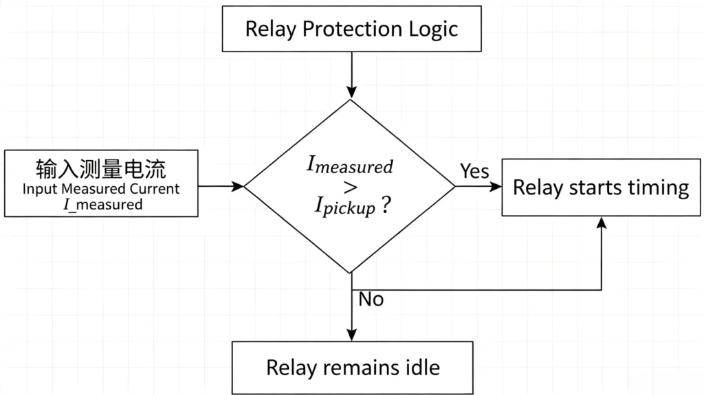
Why it matters:
The pickup setting determines the relay’s sensitivity. Set it too low → nuisance tripping. Set it too high → delayed fault detection.
Setting considerations:
- Pickup must be set above maximum load current to avoid false tripping
- A safety margin of 1.1–1.2 × maximum load current is typical
- Pickup setting must coordinate with downstream protection devices
ANSI 50: Instantaneous Protection
What it does:
When the measured current exceeds the instantaneous pickup setting, the relay trips without intentional time delay: typically within 40–80 ms.
Characteristics:
- Very high pickup setting: typically 8–12 × rated current
- No intentional time delay
- Covers the first 80–85% of the feeder (from the source)
When it operates:
- Severe short circuits near the source
- Phase-to-phase and three-phase faults
- Faults with very high current magnitude
Why it matters:
Instantaneous protection clears the most severe faults in the shortest possible time, limiting mechanical and thermal damage to cables and equipment.
ANSI 51: Time Overcurrent Protection
What it does:
When the measured current exceeds the pickup setting but is below the instantaneous threshold, the relay operates according to a time-current curve. The higher the current, the faster the relay trips.
Characteristics:
- Lower pickup setting than instantaneous (typically 1.1–1.5 × rated current)
- Time delay depends on current magnitude (IDMT) or is fixed (Definite Time)
- Covers the full length of the feeder
Time-current curve types:
| Curve Type | Characteristic | Application |
|---|---|---|
| IDMT (Inverse) | Time decreases as current increases | General coordination with downstream fuses/relays |
| Very Inverse | Steeper curve: faster for higher currents | Protection of cables and transformers |
| Extremely Inverse | Very steep, used with fuses | Coordination with fuses |
| Definite Time | Fixed delay regardless of current | Simple systems with short feeders |
Operating principle (IDMT):
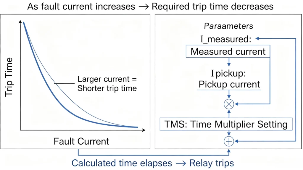
Why it matters:
Time overcurrent protection provides full-line coverage and coordination with downstream devices, ensuring selective fault clearing.
Trip Output
What it does:
When the conditions for tripping are satisfied, either instantaneously (ANSI 50) or after the time delay (ANSI 51), and the relay issues a trip command to the circuit breaker.
Trip flow:
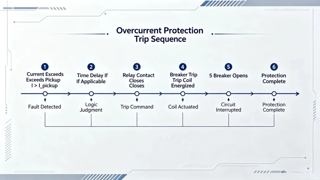
Why it matters:
The trip output is the relay’s final action, and it must be reliable, fast, and consistent to ensure fault clearance.
Trip circuit components:
- Relay output contact: Dry contact (Form-C) rated for the trip coil current
- Trip coil: Energized by the relay to release the breaker’s mechanical latch
- Circuit breaker: Opens to isolate the fault
- Trip circuit supervision: Continuously monitored to ensure the circuit is intact
Non-Directional vs Directional Overcurrent Relay
| Feature | Non-Directional Overcurrent Relay | Directional Overcurrent Relay |
|---|---|---|
| Current Magnitude Detection | Yes | Yes |
| Fault Direction Detection | No | Yes |
| ANSI Functions | 50 / 51 | 67 / 67N with 50 / 51 |
| Voltage Polarization | Normally not required | Required for directional element |
| Radial Feeders | Excellent | Usually unnecessary |
| Ring Networks | Limited | Recommended |
| Parallel Feeders | Limited | Recommended |
| Multiple Sources | Limited | Recommended |
| Reverse Fault Discrimination | No | Yes |
| Protection Complexity | Lower | Higher |
| Typical Cost | Lower | Higher |
When Should You Not Use a Non-Directional Overcurrent Relay?
Non-directional overcurrent relays are simple and reliable, but they fail in networks where fault current can flow from more than one direction.
Ring Networks
Problem: Fault current flows from both ends of the ring.
Consequence: Both ends trip, which means the entire loop loses supply.
Solution: Directional Overcurrent (67)
Parallel Feeders
Problem: Healthy feeder receives back-feed current from the faulted parallel feeder.
Consequence: Both feeders trip, and the redundancy is lost.
Solution: Directional Overcurrent (67)
Multiple Sources
Problem: Fault current paths are complex and multi-directional.
Consequence: Relays miscoordinate, and unnecessary outages occur.
Solution: Directional Overcurrent (67)
Distributed Generation (DG)
Problem: DG creates reverse fault current that non-directional relays cannot distinguish.
Consequence: Unwanted tripping of healthy feeders; loss of selectivity.
Research note: Studies show that DG integration causes reverse short-circuit current, leading to non-directional relay maloperation and coordination failure.
Solution: Directional Overcurrent (67) + Directional Earth Fault (67N)
Microgrids
Problem: Fault current changes between grid-connected (high) and islanded (low) modes.
Consequence: Relay may not trip in islanded mode; may misoperate in grid-connected mode.
Solution: Directional protection with adaptive settings
Why Is a Non-Directional Overcurrent Relay Suitable for Radial Feeders?
A radial feeder is the simplest and most common distribution network configuration, power flows in one direction only: from the source down through the feeder to the loads.
In this configuration, a non-directional overcurrent relay is not just adequate, it is the ideal choice.
Why Directional Discrimination Is Unnecessary
In a radial feeder:
- Only one power source supplies the feeder
- Fault current always comes from one direction: upstream
- Reverse fault current cannot occur: no other source exists to feed from the load side
Since the direction of fault current is always the same, the relay does not need a directional element to distinguish forward from reverse faults. It simply measures current magnitude and trips if the pickup value is exceeded.
Directional discrimination is generally unnecessary in radial feeders.
Key Advantages of Non-Directional Relays in Radial Feeders
| Advantage | Explanation |
|---|---|
| Simplicity | No VT required: only CT inputs needed |
| Lower cost | Simpler design = lower purchase and maintenance cost |
| High reliability | Fewer components = fewer failure points |
| Faster operation | No directional calculation delay |
| Easy coordination | Simple IDMT or DT curves coordinate with downstream devices |
Where Non-Directional Relays Excel
| System Type | Directional Required? | Recommended Relay |
|---|---|---|
| Single-source radial feeder | No | Non-Directional (50/51) |
| Single-source with downstream branches | No | Non-Directional (50/51) |
| Single-source with motor loads | No (unless very large motors) | Non-Directional (50/51) |
| Loop or ring network | Yes | Directional (67) |
| Parallel feeders | Yes | Directional (67) |
| Multiple sources | Yes | Directional (67) |
| Distributed generation | Yes | Directional (67 + 67N) |
When to Reconsider
A non-directional overcurrent relay remains suitable for a radial feeder as long as:
- The feeder has only one supply source
- There is no distributed generation on the load side
- The network remains radial (no loops or parallel paths)
- Fault current direction is fixed and known
If any of these conditions change, for example if a generator is added on the load side, the feeder is no longer strictly radial, and directional protection should be considered.
Non-Directional Overcurrent Relay Settings
然后只保留:
| Setting | Purpose |
|---|---|
| Pickup Current | Detect abnormal current |
| Curve | Define operating time |
| TMS / Time Dial | Adjust operating time |
| Instantaneous Pickup | Fast high-current fault clearing |
| Coordination Margin | Coordinate with upstream/downstream protection |
For detailed 50/51 setting calculations, see our Overcurrent Protection Relay Setting Guide.
Working Principle of Directional Overcurrent Relay Protection
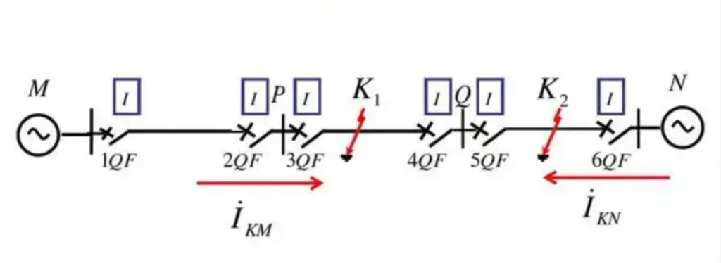
The operating core of directional overcurrent protection is phasor comparison of voltage and current. It combines overcurrent threshold judgment with directional logic locking to realize accurate fault tripping.
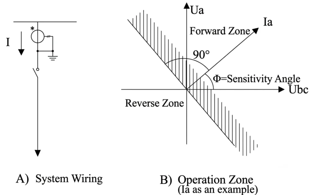
Directional Blocking Element
The directional element adopts the 90° wiring configuration, with the direction from busbar to transmission line defined as the positive direction.
The default sensitive angle of the directional element is 45°, and it is equipped with a memory function, which can eliminate the blind zone of the directional element during close-in three-phase short circuits. (The polarities of current and voltage shall be connected strictly in accordance with the above requirements during actual wiring; otherwise, abnormal direction judgment will occur.)
he schematic diagram for positive direction discrimination of the directional element is shown below:
Basic Operating Logic
- Overcurrent Pickup Judgment: Collect line current via CT; trigger pre-alarm logic when current exceeds the preset operating value
- Voltage Phase Reference: Obtain system voltage phase angle via VT as the directional judgment benchmark
- Fault Direction Calculation: Judge fault power flow direction by calculating the phase difference between fault current and voltage (active power formula: P = V × I × cosφ)
Core Trip & Block Logic
- Trip Condition: Forward fault + overcurrent exceeding threshold → execute delayed tripping
- Blocking Condition: Reverse fault (external fault of the protection zone) → lock tripping to avoid misoperation
Common Polarization Methods
- Phase-to-Phase Voltage Polarization: Suitable for most phase-to-phase short-circuit faults in distribution networks
- Phase-to-Ground Voltage Polarization: Applied to single-phase ground fault scenarios
- Memory Polarization: Solves voltage dead-zone problems for near-end short-circuit faults
- Negative Sequence Directional Polarization: Advanced algorithm for complex unbalanced fault conditions
For ANSI 67N protection, the directional element normally evaluates residual or zero-sequence quantities to determine whether an earth fault lies in the forward or reverse operating region.
When Is Directional Overcurrent Protection Required?
Directional overcurrent protection is not needed for every distribution system. In simple radial networks, where power flows in one direction from a single source to loads, standard overcurrent protection (ANSI 50/51) is sufficient.
When earth-fault current can flow in more than one direction, and non-directional ground-fault protection cannot provide adequate selectivity, 67N protection is essential.
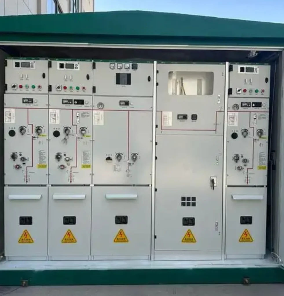
1. Ring Main Network
What it is:
A ring main network consists of feeders arranged in a closed loop, supplied from two or more sources. Power can flow in either direction around the ring.
Why directional protection is required:
In a ring network, a fault can be fed from both sides. Without directional protection, both ends of the ring may trip, which causes a complete loss of supply to the entire loop. With directional protection, only the section closest to the fault is isolated, keeping the rest of the ring energized.
2. Parallel Feeders
What it is:
Two or more feeders running in parallel between the same source and load, or between substations. This configuration is common for high-reliability applications.
Why directional protection is required:
When a fault occurs on one parallel feeder, fault current can flow from both the source side and the healthy parallel feeder (back-feed). Without directional protection, the healthy feeder may trip as well, defeating the purpose of redundancy.
3. Dual Power Supply
What it is:
A distribution system with two independent incoming power sources (e.g., main + backup, or two utility feeders). This is common in hospitals, data centers, and critical industrial facilities.
Why directional protection is required:
With two incoming sources, fault current direction depends on which source is supplying at the time of the fault. Directional protection ensures that the correct source-side breaker trips, isolating only the faulted section and maintaining supply from the other source.
4. Multiple Sources
What it is:
Distribution networks with more than two supply points, such as substations connected via tie lines, or multiple utility infeeds.
Why directional protection is required:
In multi-source networks, fault current can flow in multiple directions. Standard overcurrent relays cannot determine which source is feeding the fault, leading to potential miscoordination and unnecessary outages.
5. Distributed Generation
What it is:
Solar farms, wind turbines, cogeneration plants, or other embedded generators connected to the distribution network at the medium-voltage level.
Why directional protection is required:
Distributed generation creates bidirectional power flow. During a fault, current can flow from both the utility grid and the local generators. Directional protection prevents generators from back-feeding into the fault and ensures only the faulted feeder is isolated.
6. Microgrids
What it is:
A localized energy system that can operate in both grid-connected and islanded modes. Microgrids typically include distributed generation, energy storage, and local loads.
Why directional protection is required:
In a microgrid, fault current characteristics change depending on operating mode, whether grid-connected or islanded. Directional protection helps maintain coordination across both modes, ensuring reliable fault clearance regardless of the operating state.
7. Reverse Power Flow

What it is:
Situations where power flows from the load side back toward the source, common in networks with high penetration of solar PV, wind, or cogeneration.
Why directional protection is required:
Reverse power flow can cause conventional overcurrent relays to see fault current in the “wrong” direction. This can lead to unwanted tripping or failure to trip when needed. Directional overcurrent protection ensures correct operation regardless of power flow direction.
Quick Reference Table
| Application | Why Directional Protection Is Required |
|---|---|
| Ring Main Network | Fault can be fed from both ends, and only the faulty section needs to be isolated |
| Parallel Feeders | Fault on one feeder can back-feed through the healthy parallel feeder |
| Dual Power Supply | Two incoming sources, and identify which side is feeding the fault |
| Multiple Sources | Multiple infeeds, so fault current can flow in multiple directions |
| Distributed Generation | Solar/wind/cogeneration creates bidirectional current flow |
| Microgrids | Grid-connected and islanded modes change fault current direction |
| Reverse Power Flow | Conventional relays may see fault direction incorrectly |
Summary
Directional overcurrent protection is required whenever fault current can flow from more than one direction into a fault point. If your distribution network includes ring circuits, parallel feeders, multiple power sources, distributed generation, or microgrid operation, directional protection is not optional; it is a necessity.
For simple radial networks with a single source and no generation on the load side, standard overcurrent protection (ANSI 50/51) remains sufficient.
Protection Coordination and Setting Principles
Reasonable Protection Relay Setting Calculation is the key to ensuring directional overcurrent protection operates accurately. Unreasonable settings will directly cause refusal to trip, misoperation, or coordination failure.
Core Setting Parameters
- Pickup Current (I>): Set according to maximum load current and minimum fault current to balance sensitivity and anti-interference
- Time Delay: Adopt standard IDMT curves, match upstream and downstream time grading margin Δt
- Maximum Torque Angle: Calibrate directional judging angle to adapt to system fault characteristics
- Reverse Blocking Logic: Set strict locking thresholds for external reverse faults
System Coordination Rules
Directional overcurrent protection needs coordinated design with transformer protection, feeder backup protection, and busbar protection to form a three-level protection system and avoid protection dead zones or overlap.
Common Setting Challenges
- CT polarity reversal and VT wiring errors lead to wrong direction judgment
- Unreasonable time grading margin causes override tripping
- Improper sensitivity setting leads to refusal to trip or misoperation
- Mismatched settings in EPC staged design degrade grid protection performance
EPC Contractor Selection & Design Guide
Pre-Design System Research
- Complete short-circuit current calculation per IEC 61850 and IEEE industry standards
- Analyze power flow direction and fault current characteristics under all operating modes
- Confirm grid topology: radial / ring / mesh structure
Engineering Design Key Points
- Verify CT/VT wiring polarity and ratio accuracy to avoid directional judgment errors
- Output formal relay coordination study report and setting calculation sheet
- Reserve backup protection strategy and future grid expansion margin
Cost & Reliability Balance
Although directional relays have higher initial investment, they effectively avoid grid accidents, production shutdown losses, and equipment damage costs.
For complex industrial and new energy grids, the cost performance of directional overcurrent protection is far higher than conventional protection schemes.
Standard ANSI Protection Codes
| ANSI Code | Protection Function |
|---|---|
| 50 | Instantaneous Overcurrent Protection |
| 51 | Time-Delayed Overcurrent Protection |
| 67 | Directional Overcurrent Protection |
| 67N | Directional Earth Fault / Neutral Directional Overcurrent Protection |
| 50G/51G | Non-Directional Ground Fault Protection |
ANSI 67N protection is directional earth-fault protection used to detect earth faults and determine whether the fault is in the forward or reverse direction. It typically evaluates residual or zero-sequence current together with an appropriate polarizing quantity, allowing selective ground-fault protection in ring, parallel and multi-source networks.
What Is ANSI 67N Protection?
ANSI 67N protection is a directional earth-fault or neutral directional overcurrent function. Unlike non-directional 50N/51N protection, which mainly responds to earth-fault current magnitude, 67N also determines the fault direction before permitting a trip.
The relay typically uses residual or zero-sequence current together with a polarizing voltage or current quantity. When the earth-fault current exceeds the pickup setting and the calculated direction falls inside the configured forward operating region, the 67N element operates. Reverse faults can be blocked to maintain selectivity.
67N protection is especially useful in ring networks, parallel feeders, interconnected substations and systems with distributed generation where ground-fault current can flow from more than one direction.
Common Field Faults & Troubleshooting
- CT Polarity Reversal: Causes reverse fault misjudgment and unwanted tripping → Correct wiring and verify phasor test
- VT Loss of Voltage: Leads to failure of directional element → Configure VT loss alarm and locking logic
- Weak Grid Fault Misjudgment: Low fault voltage affects phase angle calculation → Enable memory polarization algorithm
- Coordination Failure: Unreasonable Δt causes override tripping → Recalculate settings via professional Protection Relay Setting Calculation
Advantages of Digital Microprocessor-Based Directional Relays
Modern intelligent directional overcurrent relays have completely replaced traditional electromagnetic relays, with prominent engineering advantages:
- High-precision directional algorithm adapts to complex fault conditions
- Built-in fault recording and wave recording functions for rapid fault analysis
- Support remote configuration, monitoring and online setting modification
- Perfectly compatible with substation automation and SCADA systems
- Self-diagnosis function reduces manual operation and maintenance risks
Conclusion
Directional overcurrent relay protection is worth specifying wherever fault current can reverse. Put the element, the polarisation source and the blocking logic on the single-line diagram, not in a side note, so the relay, the CTs and the VTs are procured together.
As power grid topologies grow increasingly complex and new energy sources connect to the grid on a large scale, bidirectional power flow has become a normal operating condition for modern power grids.
Directional Overcurrent Relay Protection deployed on directional overcurrent relays is used for the protection of ring and meshed networks, which can resolve the selectivity defects of conventional overcurrent protection in such complex power grids.
If you need reliable directional protection relays, ANSI 67/67N relays and various types of protective relays for ring grid and genset protection, welcome to send your parameter requirements for free technical consultation.
FAQ
1. What is directional overcurrent relay protection?
Directional overcurrent relay protection (ANSI 67) is a selective protection technology that judges fault current magnitude and direction simultaneously. It trips only for forward internal faults and blocks reverse external faults, solving misoperation problems of conventional overcurrent protection in multi-source and ring grids.
2. When should directional overcurrent relays be used?
It is applicable to all power systems with bidirectional power flow and backfeed fault risks, including ring distribution networks, parallel feeders, interconnected substations, industrial dual-power systems, and new energy microgrids.
3. What is the difference between 50/51 and 67 protection?
ANSI 50/51 is non-directional overcurrent protection, only judging current magnitude, suitable for simple radial networks; ANSI 67 adds directional judgment logic, with higher selectivity, suitable for complex bidirectional power grids.
4. Can directional relays work without voltage input?
No. The directional element relies on VT voltage phase as the reference benchmark. Without voltage polarization, it cannot identify fault direction and will lose directional protection functions.
5. How do EPC engineers set directional overcurrent relays?
EPC engineers need to complete short-circuit calculation and power flow analysis first, then formulate pickup current, time delay, directional angle and blocking logic parameters via standard Protection Relay Setting Calculation, and verify upstream and downstream protection coordination.
6. How Does a Directional Protection Relay Work?
A directional protection relay judges the fault direction by detecting the phase angle between line current and bus voltage, trips only for forward faults and uses memory voltage to eliminate dead zones during close-in three-phase short circuits.
7. What is a non-directional overcurrent relay?
A non-directional overcurrent relay detects excessive current without determining the direction of the fault current. It trips when the measured current exceeds the pickup setting, either instantaneously or after a time delay.
8. How does a non-directional overcurrent relay work?
CT measures current → Compare with pickup → I > pickup → Timer starts → Trip (instantaneous or time-delayed) → Breaker opens → Fault isolated
- ANSI 50: Instantaneous trip (no delay)
- ANSI 51: Time-delayed trip (IDMT or Definite Time)
9. Where are non-directional overcurrent relays used?
- Radial distribution feeders (single source)
- Single-source industrial and commercial systems
- Backup protection in combination with other relays
Key requirement: Fault current must always come from one fixed direction.
10. Directional vs. Non-Directional: What’s the difference?
| Aspect | Non-Directional (50/51) | Directional (67/67N) |
|---|---|---|
| Detects current magnitude | Yes | Yes |
| Detects fault direction | No | Yes |
| Requires VT | No | Yes |
| Application | Radial, single source | Looped, multi-source, parallel feeders |
| Complexity | Simple | Complex |
| Cost | Lower | Higher |
11. Why are non-directional relays used on radial feeders?
In a radial feeder, power flows in one direction only: from source to load. Fault current always flows from the source toward the fault, a fixed, known direction.
Since the direction is always the same, directional discrimination is unnecessary. Non-directional relays are the simplest, most cost-effective, and most reliable solution for radial feeders.
12. What are the limitations?
| Scenario | Problem |
|---|---|
| Ring Networks | Fault current from both ends → both trip → entire loop loses power |
| Parallel Feeders | Back-feed from healthy feeder → both trip → redundancy lost |
| Multiple Sources | Complex multi-directional paths → coordination failure |
| Distributed Generation | Reverse fault current → unwanted tripping |
| Microgrids | Fault current varies with operating mode → relay may fail |
13. What is 67N protection?
67N protection is directional earth-fault protection that detects ground or earth faults and determines their direction before allowing tripping. It typically uses residual or zero-sequence current together with an appropriate polarizing quantity and is commonly applied in ring, parallel and multi-source power systems.
14. What is the difference between 67 and 67N protection?
ANSI 67 is directional phase overcurrent protection, while ANSI 67N is directional earth-fault or neutral overcurrent protection. 67 mainly protects against directional phase faults, whereas 67N is designed to provide selective directional protection for earth or ground faults.
Related reading
- Set an overcurrent protection relay correctly for the pickup, curve and grading worksheet behind these current values.
- Earth fault relay for the residual and sensitive earth fault stages that ANSI 51N and 67N sit beside.
- ASL-441H line protection relay for the hardware that carries the directional element and its setting groups.
- Three-stage overcurrent protection when a feeder needs three separate time bands.
- Numerical overcurrent protection relay for metering, logging and communication on the same device.
Technical References and Data Sources
Requirements and limits quoted above come from the following publications and in-house application notes.
| Source | What it covers | Type | Edition |
|---|---|---|---|
| ANSI/IEEE C37.2 | Device function numbers, including 67 directional overcurrent and 67N directional earth fault | IEEE standard | C37.2-2022 |
| IEEE C37.112 | Inverse time characteristics for AC protection relays | IEEE standard | C37.112-2018 |
| IEC 60255-1 | Measuring relays and protection equipment, general performance requirements | IEC standard | 60255-1:2022 |
| IEC 61869-2 | Additional requirements for current transformers in protection circuits | IEC standard | 61869-2:2012 |
| IEC 61850-7-1 | Substation communication, protection function models and setting groups | IEC standard | Edition 2 |
| Relayprotect application note | Directional element setting worksheet and coordination worked example for an 11 kV ring main | Manufacturer document | Rev. 1, 2026 |



About Author

Hello, I'm Leno Zhang. I have 15 years of experience in the power relay protection industry with extensive pre-sales and after-sales project experience. Our company specializes in various complete sets of relay protection and automation equipment. I can assist customers in solving all practical on-site project challenges and provide optimal integrated solutions.
Tell Us Your Requirement
High Quality
Stable performance, reliable design, ensuring safe operation for power system protection and grid stability.
Fast Delivery
Timely delivery to support your urgent orders and project schedules efficiently and professionally at any time.
Best Warranty
Professional Warranty: Reliable after-sales support for stable relay protection and long-term customer satisfaction.