
-
Leon Zhang Sales Manager
-
Email: sale@relayprotect.com
-
Phone/WhatsApp: +86 13655813266
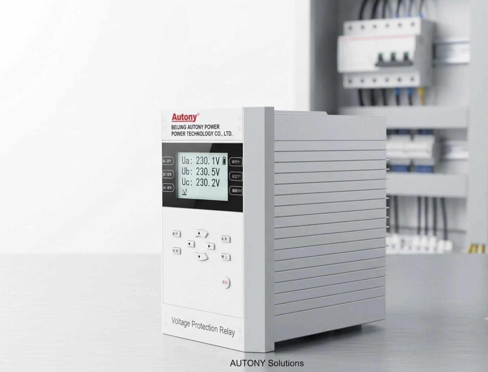
Voltage Monitoring Relay: Wiring Guide
What does a voltage monitoring relay watch and how is it wired?
A voltage monitoring relay watches the supply and drops its output contact when voltage leaves the window you define, without waiting for fault current. The four functions covering most applications are overvoltage (ANSI 59), undervoltage (ANSI 27), voltage unbalance (ANSI 47) and residual overvoltage (59N). On a 400 V system the band is often asymmetric, tighter on the low side because depressed voltage overheats motors. Phase presence catches a lost fuse; phase sequence prevents a reversed pump or compressor; unbalance is negative to positive sequence voltage, so ANSI 47 settings are far tighter than operators expect. A monitoring relay is a self-contained control-circuit device, not a system element with current inputs and event records. In three-wire systems phase-to-neutral values are derived, not measured. For 11 kV, 22 kV or 33 kV, voltage transformers step the value to 100 V or 110 V and thresholds use the secondary value; the ratio belongs in the commissioning record. Setting review and quotation within 12 hours, MOQ 1, 7-15 working days.
A voltage monitoring relay watches the supply and acts when it leaves the window you defined. It does not wait for a fault current. It looks at voltage, phase presence, phase sequence and balance, and it drops its output contact when any of those go outside limits. That contact then holds a contactor, blocks a starter, or signals a controller.
Most people meet these devices in three places: a DIN-rail unit beside a motor starter, a panel-mounted unit on a switchboard, or a monitoring function inside a multifunction protection relay. The function is the same in all three. What changes is how the voltage gets to the terminals, how the thresholds are set, and what the output is allowed to switch.
At a glance
- A voltage monitoring relay measures voltage directly or through voltage transformers, and gives a dry contact output.
- The four functions that cover most applications are overvoltage (ANSI 59), undervoltage (ANSI 27), voltage unbalance (ANSI 47) and residual overvoltage (59N). Phase failure and phase sequence are usually included on three-phase monitors.
- Direct connection is practical up to about 400 V AC line-to-line on standard DIN-rail units. Above that, a voltage transformer is used and the relay is scaled to the secondary value.
- Setting work is three numbers per stage: pickup, drop-out (or the ratio between them), and time delay.
- The output contact is a logic signal. It is not a trip circuit for a breaker unless the relay is rated and wired for that duty.

What a Voltage Monitoring Relay Watches
Four things, in order of how often they cause a call-out.
Voltage inside a band. The relay holds its output while voltage stays between a lower and an upper limit. Outside that band, the output changes state after a set delay. On a 400 V system the band is often set asymmetrically: tighter on the low side because a depressed voltage overheats motors, looser on the high side because supply voltage drifts upward at light load.
Phase presence. A lost phase on a three-phase supply is not always obvious at the terminals. One fuse operates, the motor keeps running on two phases, current rises in the remaining windings, and the damage is thermal. A monitoring relay sees the missing phase within a cycle or two and drops out.
Phase sequence. Reversed phase rotation drives a motor backwards. On a pump that means no flow and possible mechanical damage; on a compressor it can mean a locked rotor. Sequence detection is set at installation and needs no threshold.
Balance. Unbalance is measured as the ratio of negative-sequence to positive-sequence voltage, or approximated by comparing the three phase voltages. A small unbalance produces a much larger current unbalance in an induction motor, which is why ANSI 47 settings are usually far tighter than operators expect.
Monitoring Relay and Protection Relay Are Not the Same Job
The terms get used interchangeably and that causes selection mistakes. A monitoring relay is a small, self-contained device wired into a control circuit. A protection relay is a system element with current inputs, trip outputs, event records and communication.
| Aspect | Voltage monitoring relay | Protection relay with voltage functions |
|---|---|---|
| Typical mounting | DIN rail, 1 to 3 modules | Panel cut-out, 19 inch rack or flush mount |
| Inputs | Voltage only, direct or VT | Current and voltage, CT and VT |
| Output | Relay contact for control circuits | Tripping contacts, signalling contacts, communication |
| Settings | Pickup, drop-out, delay per function | Full protection scheme with coordination study |
| Records | None | Event log, disturbance records, fault values |
| Typical use | Protect a motor, pump or panel from bad supply | Protect the network, and prove what happened afterwards |
If the question is “did the supply go bad and should this motor stop”, a monitoring relay answers it at a fraction of the cost. If the question is “what fault occurred, where, and what were the currents”, that is a protection relay with recording.
Three-Phase Sensing: What the Relay Actually Measures
Three details decide whether the readings mean anything.
Three-wire or four-wire. In a three-wire system there is no neutral terminal, so phase-to-neutral values are derived, not measured. If the relay is configured for four-wire on a three-wire system, the phase voltage readings will be wrong even though the line voltage reading looks plausible.
Direct or through a VT. Direct connection is limited by the insulation rating and the supply voltage. For 11 kV, 22 kV or 33 kV, voltage transformers bring the value down to 100 V or 110 V and the relay is set in secondary terms. Every threshold you write afterward refers to the secondary value, so the ratio belongs in the commissioning record, not in someone’s memory.
Where the voltage is referenced. Line-to-line and line-to-neutral supervision are different jobs. Line-to-line catches a lost phase cleanly. Line-to-neutral catches a neutral displacement that a line-to-line measurement will hide. Systems with a floating neutral or a high-resistance ground need the second one.
The ANSI Functions Behind the Terminals
Manufacturers label the terminals with device numbers. These map to the functions below.
| Function | ANSI | What it does |
|---|---|---|
| Undervoltage | 27 | Operates when voltage falls below pickup. Used to block motor starting, transfer load, or trip a feeder that has lost supply. |
| Overvoltage | 59 | Operates when voltage rises above pickup. Protects insulation, capacitor banks and generator windings. |
| Voltage unbalance | 47 | Compares phase voltages. Detects single-phasing, uneven loading and broken conductors. |
| Residual overvoltage | 59N | Measures zero-sequence voltage from an open-delta VT or broken-delta connection. Used for ground fault detection on ungrounded systems. |
| Overexcitation | 24 | Volts per hertz. Limits core flux when a generator or transformer is driven above rated voltage for its frequency. |
| Over and under frequency | 81O / 81U | Included on many monitoring relays and on genset controllers. Related to voltage supervision but a separate measurement. |

Wiring a Voltage Monitoring Relay
The power circuit and the control circuit are separate. Getting that separation right is most of the installation.
Supply side. Three phases to the voltage terminals, through fuses or a small circuit breaker. On a direct-connected unit the same voltage that feeds the load feeds the relay. On a VT-connected unit the relay sits on the secondary winding, and the VT secondary must be earthed at one point.
Control side. The output contact goes in series with the coil of the contactor it is supervising, or into a digital input of a PLC. Use the normally-energised configuration where the application allows it: the relay holds the contact closed while voltage is healthy, so a lost control supply also stops the motor instead of leaving it running unsupervised.
Contacts are not trip circuits. A DIN-rail monitoring relay output is typically rated for a few amperes at 250 V AC. It can switch a contactor coil. It cannot interrupt a breaker trip coil circuit that draws a short-duration pulse well above that rating, and it should not be used to break a DC trip circuit without checking the DC rating.
Setting the Thresholds
Three numbers per stage. Everything else is a variant of these.
Pickup is the voltage at which the relay starts timing. Drop-out is the value at which it resets, and the gap between pickup and drop-out is the hysteresis that stops the relay chattering on a soft supply. Time delay is what separates a real disturbance from a transient dip.
Typical starting points for a 400 V three-phase motor feeder are below. They are starting points, not recommendations: the correct value depends on what the motor drives and what the upstream protection does.
| Setting | Typical starting value | Reason |
|---|---|---|
| Undervoltage pickup | 85 to 90 percent of nominal | Below this an induction motor draws excess current for the same load |
| Undervoltage delay | 2 to 5 seconds | Rides through contactor chatter and motor starting dips |
| Overvoltage pickup | 110 percent of nominal | Leaves room for light-load voltage rise on a long feeder |
| Overvoltage delay | 1 to 3 seconds | Suppresses switching transients |
| Unbalance (47) | 5 to 10 percent | Current unbalance in a motor runs several times the voltage unbalance |
| Unbalance delay | 2 to 10 seconds | Allows for genuinely unbalanced single-phase loads on the same bus |
One common mistake: setting the delay short to “catch everything”. A 0.2 second undervoltage delay will trip on every contactor operation and every motor start on the same bus. The relay then gets bypassed by the maintenance team, which is worse than a slower setting.
Which Standards Apply
Three groups matter when you compare datasheets.
IEC 60255 covers measuring relays and protection equipment: the accuracy classes, the reference conditions, and the tests that prove the declared accuracy holds. A monitoring relay quoting a 1 percent accuracy class should say which class and under which conditions.
ANSI C37.90 covers surge withstand and dielectric tests for relays. It is why a device can sit in a switchgear compartment and survive switching transients that would destroy a laboratory instrument.
IEC 61000-4 covers electromagnetic compatibility: immunity to fast transients, surges, electrostatic discharge and radiated fields. For a device mounted next to contactors and variable frequency drives, these are the numbers that predict whether it will nuisance-trip in service.
Selecting a Voltage Monitoring Relay
| Selection factor | What to check |
|---|---|
| System voltage and connection | Direct connection or VT. Confirm the rated voltage covers the highest sustained voltage, not just nominal |
| Number of phases monitored | Single-phase monitors miss phase loss. Three-phase monitors with separate phase inputs catch it |
| Functions required | 27 and 59 as a minimum. Add 47 for motors, 59N for ungrounded systems, 81 for generator applications |
| Output configuration | One changeover contact or two independent contacts. Two are needed when the relay must signal and switch at the same time |
| Contact rating | Match the contactor coil or the PLC input. Check DC ratings separately from AC |
| Mounting and size | DIN rail module count matters inside a crowded panel door |
| Display and settings access | A device with a display can be set on site. A sealed device needs a laptop or a fixed setting from the factory |
| Supply for the relay itself | Separate auxiliary supply or self-powered from the measured voltage. Self-powered units lose their output when the voltage they watch disappears |
Where Voltage Monitoring Goes Wrong in the Field
Nuisance tripping during motor starts. A large motor starting on a weak supply pulls the bus voltage down for a second or two. The monitoring relay sees undervoltage and trips the very motor that caused it, plus every other motor on the bus. Fix with delay, not with a lower pickup. The technique is the same one used for general trip problems in protection relays.
No trip when a phase is lost. Usually a wiring issue, not a setting issue. If all three voltage inputs are fed from the same phase through a shared fuse, the relay sees three healthy phases until that fuse operates, and then sees zero on all three. Check the fusing: each voltage input needs its own protection.
Chattering output on a soft supply. Hysteresis too narrow. A relay set to pick up at 90 percent and reset at 89.5 percent will oscillate for as long as the voltage sits between the two. Widen the drop-out gap to at least 3 to 5 percent.
Reading drift after a VT change. The thresholds are set in secondary volts. Replace a VT with a different ratio and every threshold silently shifts. Record the ratio on the panel, not only in the commissioning file.

Solar, Generator and Motor Applications
Solar inverters. Grid-tied inverters ride through voltage disturbances up to the limits in their grid code. A monitoring relay set to the same trip curve will disconnect before the inverter does, which defeats the ride-through requirement. Set the relay outside the inverter envelope and coordinate with the solar substation protection scheme rather than in isolation.
Generators. On load rejection a generator’s voltage rises before the regulator brings it back. A 59 element with a short delay protects the winding insulation. On a diesel generator set, the same function also prevents the changeover logic from closing onto an abnormal source.
Motors and pumps. Phase loss and unbalance protection are the two functions that pay for the device. A pump running on two phases will fail within hours. Related supervision on the process side is covered under pump station control.
Capacitor banks. Overvoltage is the main risk to capacitor insulation, and a bank that stays connected after the voltage rises will fail early. Capacitor protection is usually handled by a dedicated relay with its own unbalance input, such as the ASC-441H capacitor bank relay.
Technical Reference
Numbers a specification sheet should state, and that a buyer should check.
| Parameter | What it should state |
|---|---|
| Measuring range | Rated voltage plus the sustained overvoltage it tolerates without damage |
| Accuracy | Percent of reading or percent of full scale, and the reference conditions |
| Repeatability | Variation across repeated operations at the same voltage |
| Burden | Load the relay places on the voltage transformer, in VA |
| Setting resolution | The smallest step the threshold can be set to |
| Reset mode | Auto reset, manual reset, or both, and the drop-out ratio |
| Output contact rating | AC and DC, separately, with the load type |
| Operating temperature | Storage and operating ranges stated separately |
Related Reading
- Phase sequence and phase failure protection
- Capacitor bank protection
- Feeder protection in distribution networks
- Busbar differential protection
- Earth fault protection
- Digital fault recorder for substations
Frequently Asked Questions
What is the difference between a voltage monitoring relay and a voltage protection relay?
They measure the same quantity and answer different questions. A monitoring relay is a compact device with a control contact, used to protect a load or a panel from bad supply. A protection relay with voltage functions sits in a scheme with current inputs, trip outputs and records, and is part of the network protection design. Many applications only need the first.
Can a voltage monitoring relay work on a 3-phase 3-wire system without a neutral?
Yes, if it is configured for three-wire measurement. In that mode phase-to-neutral values are calculated rather than measured. Setting a three-wire system on a four-wire configuration gives plausible but wrong phase voltages.
How do I set the undervoltage pickup for a motor feeder?
Start at 85 to 90 percent of nominal with a delay of 2 to 5 seconds. The delay matters more than the pickup: most spurious operations come from motor starting dips that a longer delay would ride through.
Why does the relay chatter instead of staying tripped?
Hysteresis is too narrow. If pickup and drop-out sit within a fraction of a percent, the output will oscillate whenever voltage settles between them. Widen the drop-out gap to 3 to 5 percent, or increase the reset delay.
Does a monitoring relay protect against a lost phase?
Only if it measures all three phases independently. Single-phase monitors and phase-to-phase monitors configured for line voltage can miss a lost phase when the remaining phases still produce a normal line-to-line reading.
What contact rating do I need?
Match it to what the contact switches. A contactor coil of a few VA is easy. A DC trip circuit is not: check the DC rating separately, and use an interposing relay if the monitoring relay is not rated for it.
Is a voltage monitoring relay needed if there is already a protection relay on the feeder?
Often not, if the protection relay includes 27 and 59 functions and they have been set. The monitoring relay earns its place when a single load needs local supervision that the feeder scheme should not be changed to provide.
What is unbalance protection for?
To detect a condition where the three phase voltages are not equal. The voltage difference may be small while the resulting current difference in a motor is large, which makes a tight 47 setting more valuable than it looks on paper.
Conclusion
A voltage monitoring relay is a small device with a narrow job: watch the supply, hold a contact while it is healthy, release it when it is not. The work is in the three details that decide whether it does that reliably. Match the sensing to the system: three-wire or four-wire, direct or through a VT. Set the delay long enough to ride through normal operations and short enough to protect the load. And keep the voltage transformer ratio written down where the next person will find it.
For a model recommendation, send the system voltage and the load details to our engineering team.
About Author

Hello, I'm Leon Zhang. I have 15 years of experience in the power relay protection industry with extensive pre-sales and after-sales project experience. Our company specializes in various complete sets of relay protection and automation equipment. I can assist customers in solving all practical on-site project challenges and provide optimal integrated solutions.
Tell Us Your Requirement



High Quality
Stable performance, reliable design, ensuring safe operation for power system protection and grid stability.
Fast Delivery
Timely delivery to support your urgent orders and project schedules efficiently and professionally at any time.
Best Warranty
Professional Warranty: Reliable after-sales support for stable relay protection and long-term customer satisfaction.