

-
Leon Zhang sales consultant
-
Email: zxl635973785@gmail.com
-
Phone/WhatsApp: +86 13655813266
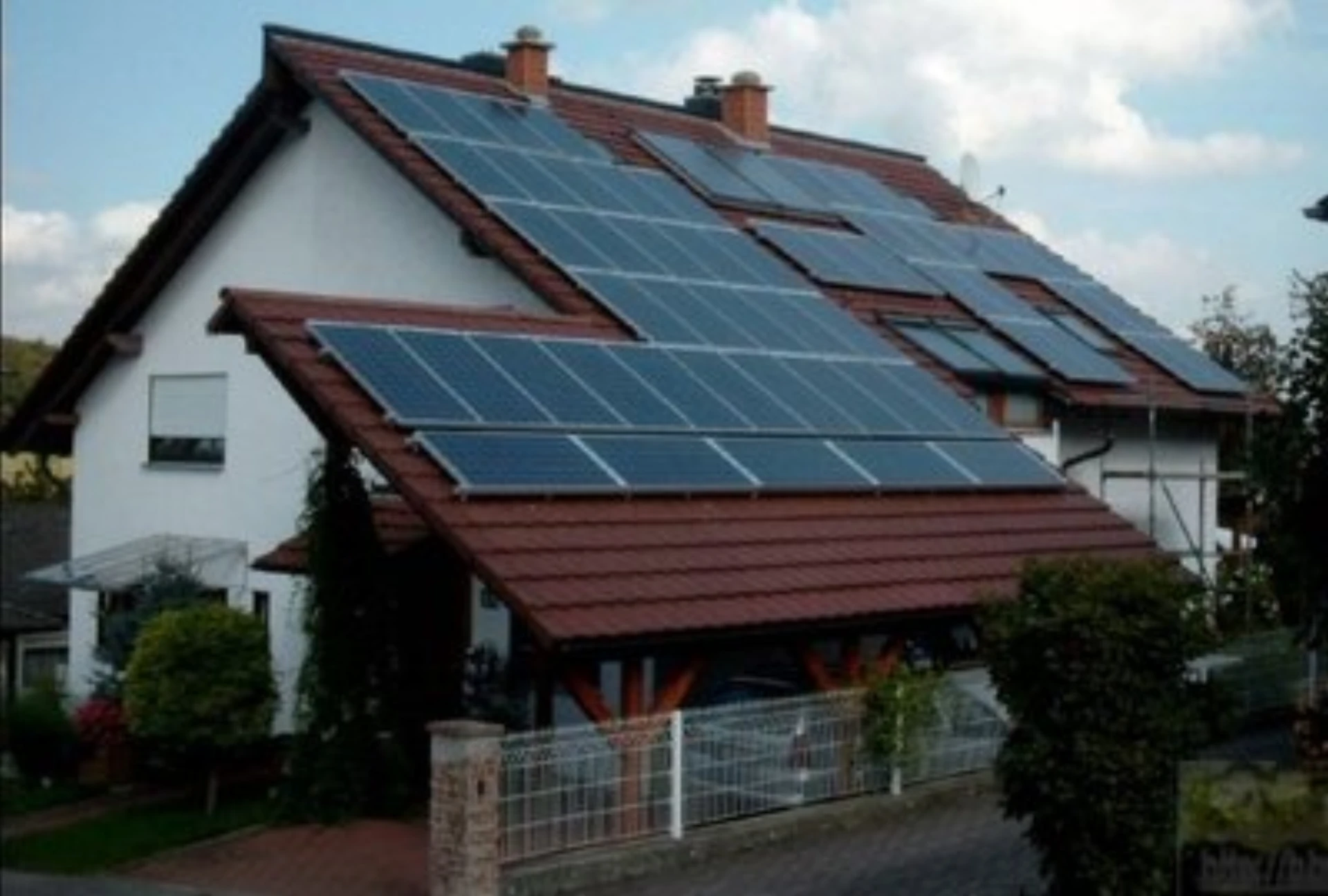
Application of Relay Protection and Automation in 3 MW Rooftop Photovoltaic Solar Power Systems
Relay protection for PV power systems watches four current paths: the inverter AC terminal, the collector line, the step-up transformer or bus, and the point where the plant meets the utility grid. ANSI functions 51/51N, 27/59 and 81 cover those paths, and IEC 62116, IEC 61727 and the interconnection clause of the grid code set the limits.
At a Glance
- Case used below: 3 MW rooftop array at Hebei Tiefeng Environmental Protection Science and Technology Park, supplied as secondary equipment only.
- Grid connection: communication debug with the municipal and county dispatch centres closed on 28 April 2025; the plant connected to the grid inside the 30 April window set by the client.
- Inverter interface: a dedicated anti-islanding device at the coupling point, plus over and under voltage 59/27 and over and under frequency 81.
- Collector and grid-connection line: overcurrent 51 and residual 51N on each feeder, with directional 67 wherever the utility can feed the same line back.
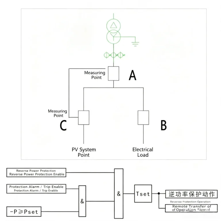
- Reverse power: a directional power 32 stage stops the plant exporting into a feeder that has no load left to take it.
- Automation: telecontrol communication panel, protocol conversion unit, common control and measurement device, and a longitudinal encryption unit on the dispatch path.
- Time synchronisation: IRIG-B or 1 PPS to every device, so inverter events, relay trips and the power quality recorder sit on one timeline.
- Standards behind the scheme: IEC 62116 for the anti-islanding test, IEC 61727 for the array, IEC 60255 for the relays, and the grid code interconnection clause for the trip logic.
The array makes direct current. The inverter makes it usable. The relay decides what happens when the grid disappears.
The project below is the layout most rooftop plants use: an inverter block, one collector feeder to the building switchroom or a pad-mounted transformer, and a single protection and telecontrol cabinet at the grid point.
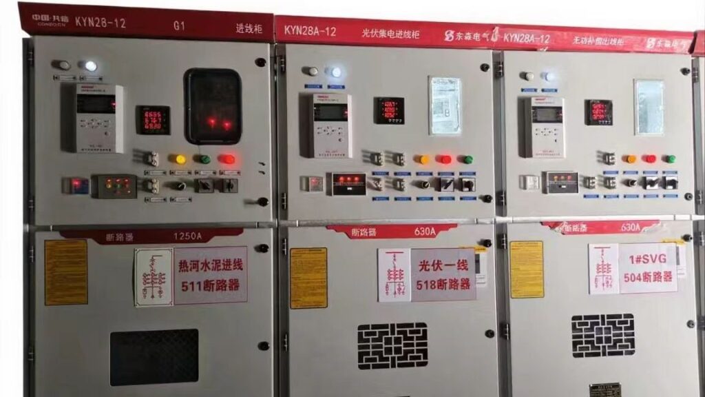
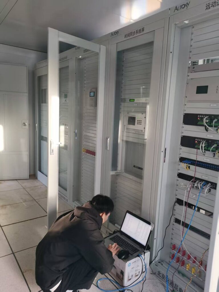
In April 2025 Beijing Antongni Electronic Technology Co., Ltd. supplied all secondary equipment for the 3 MW rooftop project at Hebei Tiefeng Environmental Protection Science and Technology Park. The scope covered a complete distributed PV monitoring system, the protection and telecontrol panels at the coupling point, and the instruments the two dispatch centres asked for.
Commissioning closed on 28 April 2025.
Grid connection followed inside the client’s 30 April deadline.
Standards That Bound This Scheme
Relay protection for PV power systems is drawn up against IEC 60255 for measuring and protecting relays, IEC 61850 and IEC 60870-5-103 for the station bus and the dispatch path, and IEC 62116, which is the test standard for anti-islanding. IEC 61727 covers the array itself, and IEEE 1547 is the reference most utilities quote when they write interconnection behaviour into a grid code.
A setting that has no standard behind it is a guess.
What This Page Covers
The sections below take the 3 MW rooftop layout apart: the relays at the inverter, the collector and grid-connection lines, the products installed on site, what the delivery team was up against, the standards behind the scheme, and the questions engineers ask before they order.
Products Provided for Rooftop Photovoltaic Solar Power Systems
In this project, Antongni provided the following products:
- Distributed PV Monitoring System
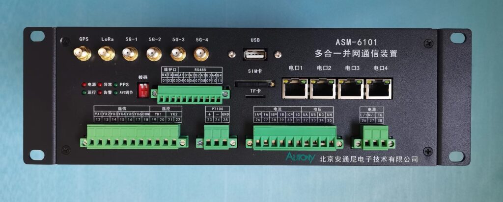
- Telecontrol Communication Panel: Including an all-in-one grid-connection communication device, protocol conversion device, common control and measurement device, and longitudinal encryption authentication device.
- Clock Synchronization System Panel: Including two clock synchronization devices.
- Anti-islanding Protection and Power Quality Panel: Including one anti-islanding protection device and one power quality online monitoring device.
- Solar Power Prediction System
- Primary Frequency Regulation System
- Integrated Power Supply System
- Collector Line Protection and Grid-connection Line Protection Devices
Protection Scheme of a 3 MW Rooftop Plant
Relay protection for PV power systems on a rooftop plant runs with an inverter in the loop instead of a synchronous machine, which changes what a relay can assume. Current stops when the sun stops, fault current is limited by the inverter switches rather than by impedance, and the grid can vanish while the array is still producing. 3MW solar protection starts from those three facts.
Relays at the inverter
Every string reaches a combiner box and then an inverter. The inverter itself will not hold a dead grid, and most units also trip on over or under voltage and frequency. The panel at the coupling point still carries a dedicated anti-islanding protection device with its own trip output to the breaker, because the grid code and the dispatch agreement name a device the utility can verify, not a setting buried in an inverter menu.
That is where the 3 MW rooftop case above put its anti-islanding relay.
Collector and grid-connection lines
Distributed arrays run radial strings, not networks with loops, so overcurrent 51 and residual 51N relays grade by distance with a time step between them. Where the building switchroom can also be fed from the utility in the other direction, add directional 67 so the relay knows which way the current is going. The grid-connection line takes the same functions with a faster clear, and a reverse power stage handles the case set out in the low-voltage PV reverse power protection case study.
One string fault should not empty the roof.
Where rooftop trips usually come from
Three conditions stop healthy rooftop plant. A cloud edge moves output in seconds, and a pickup set inside that transient band sees it as a fault. Inverter switching current carries harmonics that a plain overcurrent curve misreads. After sunset the coupling point can still push power back into a feeder whose load has switched off. The relay side of each fix is a transient block, a filtered pickup, and a directional power stage.
Clouds move faster than a thermal pickup.
Rooftop PV protection lives with those three conditions instead of trying to out-muscle them.
Implementation Status
Relay protection for PV power systems on a distributed roof is a secondary-side job, and this one had to reach site ready to debug. The design window ran for months. The delivery window ran for weeks.
Grid connection is the date the plant starts earning, so the telecontrol chain to both dispatch centres was the critical path. The debug closed on 28 April 2025, two days ahead of the deadline.
- Pre-sales Technical Support: The technical team engaged in exhaustive communication with the client and the design institute across all stages, from grid-connection planning through technical implementation to blueprint design, so the design institute held what it needed for the panel drawing.
- Delivery Assurance: Faced with the “430” grid-connection deadline, short-term orders, and tight delivery schedules, Antongni’s delivery team responded rapidly. The delivery team pulled panel building forward and kept a commissioning engineer on site through the debug window, which is what closed the telecontrol chain to the two dispatch centres in time.
III. Core Products
Relay protection for PV power systems on a rooftop plant is a short parts list. Two products carried most of the work on this site: the monitoring platform and the grid-connection communication unit.
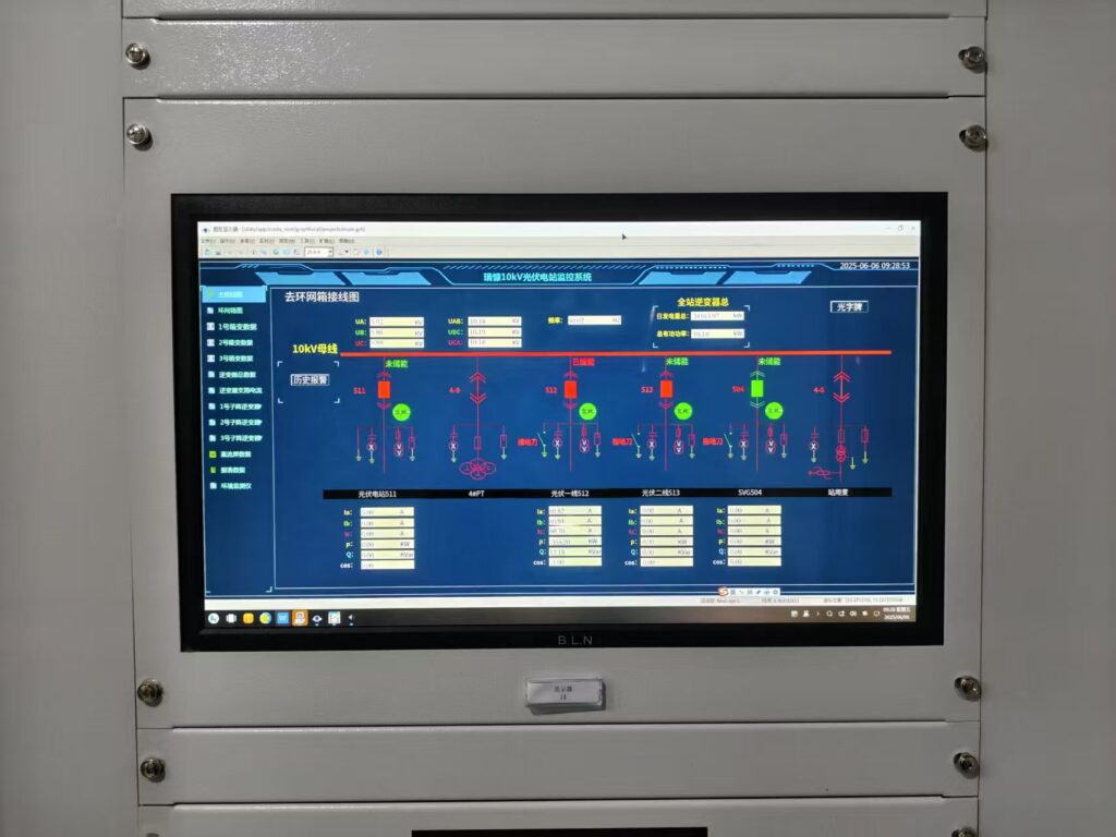
- ATN-2000P Distributed PV Monitoring System: Utilizing an advanced architecture, it collects real-time data such as power generation and voltage for intelligent management through analysis. Its stable performance improves management efficiency and reliability, enabling timely detection of equipment hazards to reduce downtime and ensure stable power station operation. PV automation on this site runs on that platform: generation and voltage data from every feeder land in one screen, and an alarm that fires at 03:00 names the string.
- ASM-6101H All-in-one Grid-connection Communication Device: This device precisely meets the power grid’s “Four Controllables” requirements. Through efficient communication links, it accurately uploads generation data and receives dispatch instructions while flexibly adjusting generation power to ensure safe and stable grid connection.
IV. User Recognition
Short orders and an urgent debug window were the two constraints on this order. The delivery team moved the panel build forward, and the commissioning crew stayed on site through the 28 April debug session. The plant reached the grid before the 30 April deadline and the operator signed the commissioning record.
The scope is the part worth reading twice: this was secondary equipment only. Relays, telecontrol panels, time synchronisation, power quality monitoring and the dispatch communication chain, with the array, inverters and primary switchgear supplied elsewhere.
Conclusion
| No. | English Name | Core Function |
|---|---|---|
| 1 | Microprocessor-based protection devices (overcurrent, overvoltage, zero-sequence protection) | Core secondary protection unit; detects overcurrent, overvoltage and zero-sequence faults to trigger tripping and isolate faulty sections. |
| 2 | Anti-islanding protection devices | Identifies islanding operating conditions and trips the system to eliminate hazards caused by off-grid standalone PV operation. |
| 3 | Fault disconnection devices | Separates PV plants from utility grids during grid faults to prevent fault propagation between generation side and grid side. |
| 4 | Online power quality monitoring devices | Performs 24/7 real-time monitoring on grid-connected power quality indexes and records abnormal data to meet grid compliance requirements. |
| 5 | Substation measurement and control devices | Collects analog and digital status signals and supports remote switch control as core automation equipment for PV substations. |
| 6 | Telecontrol communication panels | Establishes communication links between PV station and dispatching center for data upload and downlink of dispatch commands. |
| 7 | Dispatch data network equipment | Builds dedicated secure transmission channels to ensure stable and low-latency delivery of telemetry and telecontrol data. |
| 8 | Secondary security panels | Implements cyber security protection for secondary systems against unauthorized access, network intrusion and data leakage. |
| 9 | GPS time synchronization devices | Supplies unified high-precision clock reference to all secondary equipment for synchronous data acquisition and consistent fault event timestamp. |
| 10 | Backend monitoring systems | Centralizes real-time data display, alarm management and historical data review to facilitate centralized and remote operation & maintenance. |
Relay protection for PV power systems comes down to four points and a clock. Protect the inverter interface, the collector line, the transformer or bus, and the grid connection. Then keep every device on one time source, so an event record says what happened instead of what someone thinks happened.
The 3 MW rooftop case above shows the practical shape of it: one protection and telecontrol cabinet at the coupling point, anti-islanding on its own trip output, 51/51N on the feeders, and IEC 60870-5-103 or IEC 61850 traffic to the dispatch centre.
That is the whole protection job.
Rooftop PV protection on a 3 MW roof does not need a transformer differential or a bus wire. It needs the four points above, one time source and a tested trip path.
The engineering covers secondary equipment for distributed PV plants from a few hundred kilowatts up to utility scale: scheme design, relay selection, panel building and whole-station commissioning. What the engineering team needs first is a single-line, the inverter list and the interconnection agreement. The setting sheet comes out of those three documents, not out of a catalogue.
Send the three documents and the protection scheme comes back as a function list with the ANSI numbers in it.
Related Reading
- Solar anti-islanding protection goes deeper into detection methods, the trip path and the settings a utility will check.
- Low-voltage PV reverse power protection case covers the night export trip at a coupling point on a building feeder.
- Secondary equipment in PV power generation splits the duties between SCADA, protection and communication.
- Step-up transformer protection covers 87T and the backup stages when the roof output reaches a pad-mounted transformer.
- Relay protection training and testing is how the trip paths get verified before handover.
Standards Referenced
- IEC 60255 measuring, protection and controlling relays, the equipment every function on this page sits in.
- IEC 62116 test procedure for utility-connected PV inverters, including the anti-islanding test.
- IEC 61727 photovoltaic array design, which fixes the string voltage and the array configuration a protection scheme starts from.
- IEC 61850 station bus and object modelling for the protection and telecontrol layer.
- IEC 60870-5-103 / IEC 60870-5-104 relay to station and station to control centre telecontrol, the two protocols this dispatch path was built on.
- IEEE 1547 interconnection of distributed resources, the reference most grid codes quote for voltage, frequency and ride-through behaviour.
- IEEE C37.90 communication between relays and other substation equipment.
FAQ
Q:What is a photovoltaic power system?
A photovoltaic power system is a renewable energy system that converts sunlight directly into electricity using solar panels, inverters, transformers, and monitoring equipment. These systems can be installed for residential, commercial, industrial, and utility-scale power generation applications.
Q:How does a photovoltaic system generate electricity?
A :photovoltaic system generates electricity when solar cells absorb sunlight and create a flow of direct current (DC). The inverter then converts the DC power into alternating current (AC), which can be used by electrical loads or exported to the utility grid.
Q:What are the main components of a photovoltaic power system?
A typical photovoltaic power system includes:
- Solar PV modules
- Grid-tied or hybrid inverters
- Combiner boxes
- Protection relays
- Step-up transformers
- Monitoring and SCADA systems
- Energy storage systems (optional)
Each component plays a critical role in ensuring efficient and reliable power generation.
Q:What is photovoltaic power system modeling and control?
Photovoltaic power system modeling and control refers to the process of simulating, designing, and optimizing solar power systems to improve performance, stability, and energy output. Engineers use modeling tools to analyze system behavior under different environmental and grid conditions.
Q:Why is modeling important in photovoltaic power system design?
Modeling helps engineers:
- Predict energy production
- Optimize inverter sizing
- Evaluate grid integration performance
- Reduce design errors
- Improve system reliability
Accurate modeling cuts project risk and operating cost before a single cabinet is built.
Q:What are grid converters in photovoltaic and wind power systems?
Grid converters are power electronic devices that convert renewable energy output into grid-compatible electricity. In photovoltaic and wind power systems, converters regulate voltage, frequency, and power quality while ensuring compliance with grid codes.
Does the inverter handle anti-islanding on its own?
An inverter will not hold a dead grid, and most units also react to over and under voltage and frequency. Utilities still ask for a separate anti-islanding device at the coupling point with its own trip output to the breaker, because that trip path can be checked during commissioning without opening the inverter menu. The 3 MW rooftop case above follows that pattern.
Why does a rooftop PV plant trip at night?
Relay protection for PV power systems is rarely why a rooftop plant trips at night, but it is the only thing that clears the fault once the inverter has handed over. After sunset the array can still feed a building feeder through the inverter, and once the load switches off there is nowhere for that power to go. A reverse power or directional power stage at the coupling point clears it. Daytime trips are a different list: cloud transients, a pickup set too close to the transient band, and harmonic current from the inverters.

About Author

Hello, I'm Leno Zhang. I have 15 years of experience in the power relay protection industry with extensive pre-sales and after-sales project experience. Our company specializes in various complete sets of relay protection and automation equipment. I can assist customers in solving all practical on-site project challenges and provide optimal integrated solutions.
Tell Us Your Requirement
High Quality
Stable performance, reliable design, ensuring safe operation for power system protection and grid stability.
Fast Delivery
Timely delivery to support your urgent orders and project schedules efficiently and professionally at any time.
Best Warranty
Professional Warranty: Reliable after-sales support for stable relay protection and long-term customer satisfaction.