

-
Leon Zhang sales consultant
-
Email: zxl635973785@gmail.com
-
Phone/WhatsApp: +86 13655813266
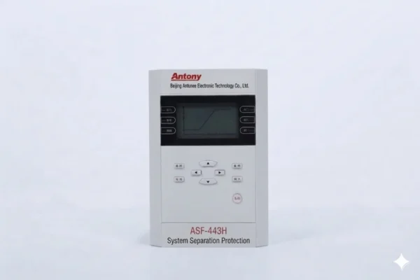
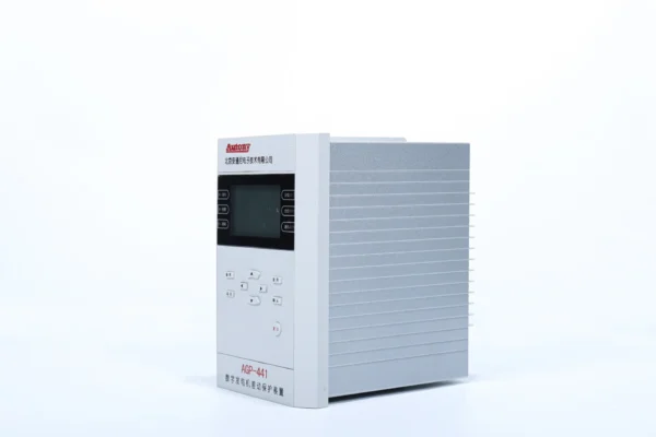
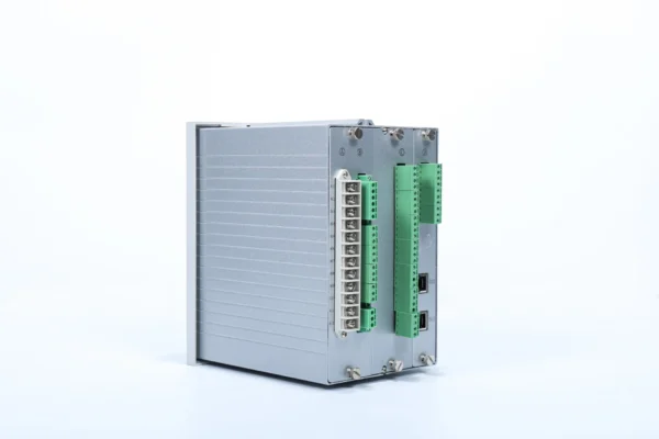
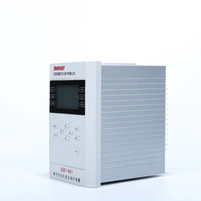
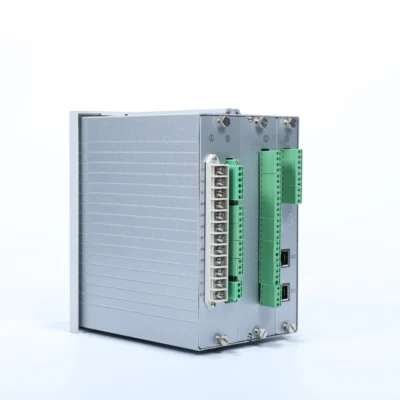
78 System Separation Protection
The System Separation Protection Device is a new-generation product independently developed and manufactured by our company. It is suitable for substations or interconnections operating with small power sources connected to medium- and low-voltage grids.
Product Functions (ANSI)
81, 27, 59, 78, 59N, 50, 51
Communication Mode
Optional: RS-485, CAN bus, Ethernet, IEC 60870-5-103 (IEC-103)
Send your requirements, we will quote for you within 12 hours
Description
- The System Separation Protection (78) Device is a new-generation product independently developed and manufactured by our company. It is suitable for substations or interconnections operating with small power sources connected to medium- and low-voltage grids.
- In the event of a grid fault, the device can quickly and reliably disconnect the small power sources from the grid to ensure the restoration of power supply from the main source and guarantee the safe and stable operation of the grid system.
- It features functions such as low-frequency disconnection, low-voltage disconnection, over-frequency disconnection, busbar overvoltage disconnection, zero-sequence overvoltage disconnection, and loss-of-synchronism disconnection.
Product Functions (ANSI)
- Frequency relay|81
- Undervoltage relay|27
- Overvoltage relay |59
- System separation relay |78
- Neutral overvoltage relay|59N
- Instantaneous Overcurrent|50
- Time Delayed Overcurrent|51
Communication Mode
- Optional: RS-485, CAN bus, Ethernet, IEC 60870-5-103 (IEC-103)
Main Functional Specifications
- Protection Response Time (including output relay response time): The average response time error is no more than 35 ms.
- Precision Operating Range: The minimum precision current is 0.08 In, and the maximum precision current is 20 In.
- Setting Accuracy: The current setting error is within ±2.5% for current values above 1.00 A; the voltage setting error shall not exceed ±3%.
- Measurement Accuracy: Current (I) and Voltage (U) meet Class 0.2 accuracy; Active power (P) and Reactive power (Q) meet Class 0.5 accuracy.
- Remote Signal Resolution: ≤ 2 ms.
Event Logging, Fault Recording
- The recorded events include protective action events and device malfunctions;
- Record the type of protection trip, the time of the trip, and the operating parameters at the time of the trip;
- The fault recording data includes: the time of the protection operation, the type of protection operation, and the rms values before and after the recording was initiated;
- Data length of the fault recording: 2 cycles before the fault and 4 cycles after the fault;
- The SOE can retain 48 sets of data after a power loss, and the fault report can retain 16 sets of data after a power loss.
Monitoring Features
- This device measures analog parameters including current, voltage and frequency.
- It acquires digital signals such as status data from circuit breakers, energy storage systems, disconnectors and remote/local control switches, and supports disconnector control functions.
Setting Table
| No. | Definition | Display | Setting Range | Default Value | Main Program | Remarks |
|---|---|---|---|---|---|---|
| 1 | Control Word 1 | 0000~FFFF | 0000 to FFFF | 0x0000 | – | – |
| 2 | Control Word 2 | 0000~FFFF | 0000 to FFFF | 0x0000 | – | – |
| 3 | Control Word 3 | 0000~FFFF | 0000 to FFFF | 0x0000 | – | – |
| 4 | Low Frequency Start-up Delay | 0.1~120.00s | 0.1 to 120.00 s | 1.00 s | – | – |
| 5 | Low Frequency Stage 1 Delay | 0.1~120.00s | 0.1 to 120.00 s | 1.00 s | – | – |
| 6 | Low Frequency Stage 2 Delay | 0.1~120.00s | 0.1 to 120.00 s | 1.00 s | – | – |
| 7 | Over Frequency Stage 1 Delay | 0.1~120.00s | 0.1 to 120.00 s | 1.00 s | – | – |
| 8 | Over Frequency Stage 2 Delay | 0.1~120.00s | 0.1 to 120.00 s | 1.00 s | – | – |
| 9 | Under Voltage Start-up Delay | 0.1~120.00s | 0.1 to 120.00 s | 1.00 s | – | – |
| 10 | Under Voltage Stage 1 Protection Delay | 0.1~120.00s | 0.1 to 120.00 s | 1.00 s | – | – |
| 11 | Under Voltage Stage 2 Protection Delay | 0.1~120.00s | 0.1 to 120.00 s | 1.00 s | – | – |
| 12 | Over Voltage Stage 1 Protection Delay | 0.1~120.00s | 0.1 to 120.00 s | 1.00 s | – | – |
| 13 | Over Voltage Stage 2 Protection Delay | 0.1~120.00s | 0.1 to 120.00 s | 1.00 s | – | – |
| 14 | Over Current Stage 1 Delay | 0~120.00s | 0 to 120.00 s | 1.00 s | – | – |
| 15 | Over Current Stage 2 Delay | 0~120.00s | 0 to 120.00 s | 1.00 s | – | – |
| 16 | Over Current Stage 3 Delay | 0~120.00s | 0 to 120.00 s | 1.00 s | – | – |
| 17 | Zero Voltage Stage 1 Protection Delay | 0.1~120.00s | 0.1 to 120.00 s | 5.00 s | – | – |
| 18 | Zero Voltage Stage 2 Protection Delay | 0.1~120.00s | 0.1 to 120.00 s | 5.00 s | – | – |
| 19 | Reserved | 0.1~120.00s | 0.1 to 120.00 s | 5.00 s | – | – |
| 20 | Reserved | 0.1~120.00s | 0.1 to 120.00 s | 5.00 s | – | – |
| 21 | Low Frequency Start-up Setting Value | 45.00~50.00Hz | 45.00 to 50.00 Hz | 49.50 Hz | – | – |
| 22 | Low Frequency Stage 1 Protection Setting Value | 45.00~50.00Hz | 45.00 to 50.00 Hz | 49.00 Hz | – | – |
| 23 | Low Frequency Stage 2 Protection Setting Value | 45.00~50.00Hz | 45.00 to 50.00 Hz | 48.50 Hz | – | – |
| 24 | Over Frequency Stage 1 Protection Setting Value | 50.00~55.00Hz | 50.00 to 55.00 Hz | 51.00 Hz | – | – |
| 25 | Over Frequency Stage 2 Protection Setting Value | 50.00~55.00Hz | 50.00 to 55.00 Hz | 52.00 Hz | – | – |
| 26 | Frequency Change Rate (Blocking Setting Value), df/dt2 | 0.00Hz/s~20.00Hz/s | 0.00 Hz/s to 20.00 Hz/s | 1.00 Hz/s | – |
|
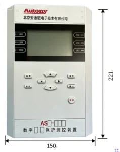
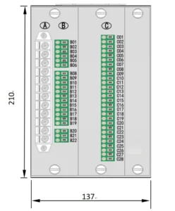
Outline and Installation Dimensions
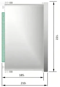
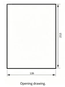
FAQ
Q:In what types of projects are system separation protection devices primarily used?
A:System separation protection devices are primarily used in power generation projects, such as hydroelectric, thermal, and photovoltaic power plants. In the event of a fault on the generation side, these devices immediately isolate the faulty section to ensure the safety of the power grid.
Q:Where are system separation protection devices typically installed?
A:System separation protection devices are typically installed in parallel and are mainly located in the secondary distribution rooms of substations; however, they may sometimes be installed on high-voltage switchgear for grid connection depending on specific requirements.
Q: What is a Fault Separation Device?
A: It is a dedicated protection device used to split power grid sections automatically when system faults or abnormal operating conditions occur, preventing grid collapse and ensuring stable operation of the remaining power supply area.
Q: What main working conditions trigger separation action?
A: It executes splitting under conditions including power system out-of-step oscillation, severe frequency deviation, abnormal voltage fluctuation, overload tie line and main grid fault loss.
Q: Where is this device generally installed?
A: It is mainly arranged on tie lines between regional power grids, power plant outgoing lines and important contact feeders of substations to realize islanding protection of power grids.
Q: What electrical signals need to be accessed?
A: Three-phase voltage and three-phase current of the tie line are required for calculation of power angle, active power, reactive power, frequency and voltage amplitude.
Q: Can the action delay time be set on site?
A: Yes. The splitting delay threshold, action criteria and locking conditions can be flexibly configured via local panel operation or remote background software with password authorization.
Q: Does it support interlock blocking logic?
A: Blocking functions can be enabled such as manual switching lockout, circuit breaker position interlock and fault locking to avoid false splitting under normal switching operations.
Q: What communication protocols are available for data upload?
A: It supports IEC 60870-5-104, Modbus TCP and IEC 61850, uploading action events, fault information and real-time operation data to the master monitoring system.
Q: Will the device record fault and action records?
A: It automatically records action time, splitting cause, electrical quantity before and after fault and wave recording files, supporting local query and remote export for accident analysis.
Q: What auxiliary power supply does the device need?
A: Standard working power adopts DC 110V or DC 220V, which matches the power supply specification of conventional substation secondary protection panels.
Q: What is the warranty and supporting documents?
A: The standard warranty period is 24 months from delivery. The product is delivered with principle drawings, terminal wiring diagrams and complete operation & setting manuals.
2 reviews for 78 System Separation Protection
Related products
High Quality
Stable performance, reliable design, ensuring safe operation for power system protection and grid stability.
Fast Delivery
Timely delivery to support your urgent orders and project schedules efficiently and professionally at any time.
Best Warranty
Professional Warranty: Reliable after-sales support for stable relay protection and long-term customer satisfaction.
xiao zhang –
This separation relay monitors grid voltage & frequency deviation, rapidly splits small power sources from main grid during system fault. Flexible threshold setup and multi communication for distributed PV, wind and captive power plants.
Jack –
Event records are stored reliably even after a complete power loss.