

-
Leon Zhang sales consultant
-
Email: zxl635973785@gmail.com
-
Phone/WhatsApp: +86 13655813266
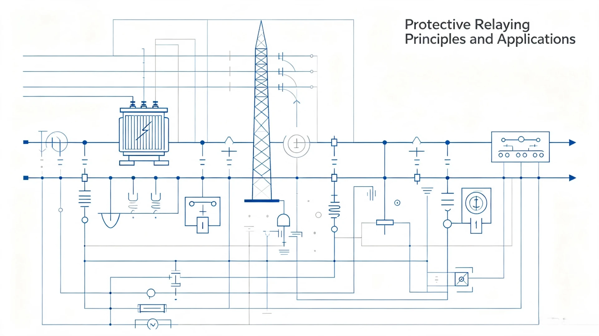
Protective Relaying Principles and Applications: Understand, Configure and Select Power‑System Protective Relays
Introduction to Protective Relaying
Applied protective relaying forms the primary safety backbone for modern power systems, industrial plants, renewable sites and utility substations. A protective relay continuously monitors electrical operating conditions, detects faults or abnormal states, and issues trip signals to circuit breakers to isolate faulty equipment quickly.
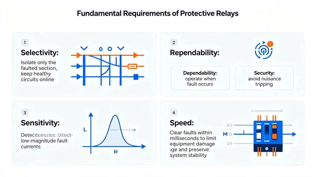
Fundamental Requirements of Protective Relays
- Selectivity: Isolate only the faulted section, keep healthy circuits online
- Reliability: Dependability (operate when fault occurs) and security (avoid nuisance tripping)
- Sensitivity: Detect low‑magnitude fault currents
- Speed: Clear faults within milliseconds to limit equipment damage and preserve system stability
Without properly engineered protective relaying, short‑circuits, ground faults and equipment failures can lead to transformer burnout, generator damage, extended plant outages, and safety hazards for site personnel. For EPC contractors and asset owners, correct protection configuration directly reduces total‑cost‑of‑ownership by lowering unplanned downtime and asset replacement costs.
This paper mainly introduces protective relaying principles and applications, providing practical references for EPC contractors and asset owners.
Core Protective Relay Principles
Fault Detection
Relays acquire real‑time measurements from current transformers (CTs) and voltage transformers (VTs/PTs). Measured quantities include phase current, residual current, phase‑to‑phase voltage, frequency, impedance, and active/reverse power. When measured values deviate from pre‑defined thresholds, internal protection algorithms evaluate whether a genuine fault exists.
Fault Classification
Power system faults fall into two major groups: short‑circuit faults and abnormal operating conditions.
- Phase‑to‑phase faults
- Phase‑to‑ground faults
- Three‑phase short‑circuits (most severe fault event)
- Open‑circuit conditions, overload, under‑frequency, reverse power flow
Selectivity: Primary and Backup Protection
Primary protection: First‑line protection for each piece of equipment, operates at fastest time delay for faults within its protection zone. Backup protection: Secondary protection for adjacent zones, activates if primary protection fails to trip. Backup protection prevents total system collapse caused by protection device failure.
Reliability: Dependability vs Security
- Dependability: Relay must trip for in‑zone faults.
- Security: Relay must restrain from tripping for external faults or normal transients (motor starting, transformer inrush).
Poor balance between the two creates two common field failures: failure‑to‑trip and unwanted nuisance tripping.
Sensitivity and Operating Speed
Sensitivity defines the minimum fault magnitude that can trigger reliable operation. Operating speed determines how fast fault energy is removed. High‑speed clearance is critical for generators, busbars and large‑capacity industrial loads to avoid irreversible thermal and mechanical damage.
How Does a Protection Relay Work?
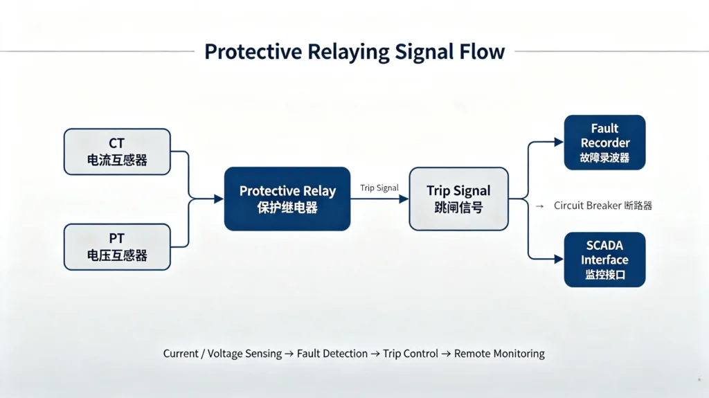
The signal‑to‑trip workflow follows a fixed practical sequence:
- CT / VT signal acquisition: Instrument transformers step down high primary current and voltage to secondary‑level signals safe for relay hardware.
- Signal conditioning & measurement: Analog signals are sampled and converted into digital values.
- Protection algorithm execution: Compare measured values against configured pickup, time‑delay and characteristic curves.
- Trip command output: If fault criteria are satisfied, dry‑contact or binary output sends trip signal to circuit breaker.
- Fault recording & event logging: Capture fault waveforms, event timestamps, SOE (Sequence‑of‑Events) data for post‑fault analysis.
- Substation communication: Upload fault records, alarms and real‑time status to SCADA or IEC‑61850‑based substation automation systems.
Types of Electrical Protective Relays
Below table summarizes widely‑used protection functions, ANSI device numbers and typical application scope.
| Protection Function | ANSI Code | Typical Application |
|---|---|---|
| Instantaneous / Time‑delayed Overcurrent | 50 / 51 | Feeders, motors, transformer backup |
| Earth / Ground Fault Protection | 50N/51N, 50G/51G | Feeders, transformers, industrial earthing systems |
| Differential Protection | 87 | Transformers, generators, busbars |
| Distance Protection | 21 | High‑voltage transmission lines |
| Directional Overcurrent | 67 / 67N | Meshed distribution & interconnected networks |
| Undervoltage / Overvoltage | 27 / 59 | Generators, motors, busbar voltage supervision |
| Under‑ / Over‑frequency | 81U / 81O | Generator islanding, load‑shedding schemes |
| Reverse Power Protection | 32 | Generator motoring protection, distributed generation anti‑islanding |
Overcurrent Protection Relay (ANSI 50 / 51)
Time‑delayed (51) overcurrent responds to sustained overload and moderate short‑circuit currents. Instantaneous overcurrent (50) provides fast tripping for high‑magnitude short‑circuits. Widely deployed for distribution feeders, motor and transformer backup protection.
Earth Fault and Ground Fault Protection (ANSI 50N/51N, 50G/51G)
Detects residual ground fault current. Critical for solidly‑grounded and resistance‑grounded systems. Earth fault settings are normally lower than phase‑fault pickup values to detect low‑level ground faults that phase overcurrent cannot capture.
Differential Protection Relay (ANSI 87)
Compares incoming and outgoing current across protected equipment. Any current imbalance indicates internal fault. Offers high‑speed primary protection for transformers, generators and busbars. Requires correct CT polarity matching on both sides of protected zone.
Distance Protection Relay (ANSI 21)
Measures impedance between relay location and fault point. Divided into Zone 1, Zone 2 and Zone 3 stepped protection zones. Standard for transmission‑line protection, immune to wide‑ranging source‑impedance variations.
Directional Overcurrent Protection (ANSI 67 / 67N)
Only operates for fault current flowing in a predefined direction. Essential for loop‑configured networks and multi‑source systems to avoid non‑selective tripping.
Under‑ / Overvoltage Protection (ANSI 27 / 59)
Monitors abnormal voltage excursions. Applied for generator loss‑of‑field detection, motor stall prevention and busbar supervision.
Under‑ / Overfrequency Protection (ANSI 81U / 81O)
Responds to frequency drift caused by generation‑load imbalance. Used for generator protection and automatic load‑shedding logic.
Reverse Power Protection (ANSI 32)
Detects power flowing backward into prime‑movers. Protects generators from motoring condition, and used for anti‑reverse‑power in solar‑PV and diesel‑generator hybrid sites.
Motor Protection Relaying
Industrial medium‑voltage motors require multi‑function protection suite: overload, locked‑rotor detection, phase‑failure protection, thermal overload modelling, and starting‑time supervision. Mis‑configured motor protection is a top source of unplanned plant downtime.
Transformer Protection Relaying
Transformer protection scope includes differential main protection, overcurrent backup, restricted earth fault,Buchholz gas alarm/trip for oil‑filled units, over‑temperature and over‑fluxing protection.
Protective Relays Application Guide
Generator Protection
Generator‑unit protection covers stator phase‑to‑phase and earth faults, rotor excitation faults, reverse‑power motoring protection, loss‑of‑excitation, and generator‑transformer unit combined protection. Setting complexity increases for synchronous generators and renewable distributed generation assets.
Transformer Protection
Both power‑transformer and distribution‑transformer protection rely on differential primary protection plus time‑graded backup overcurrent and earth‑fault functions. Oil‑filled transformers integrate Buchholz alarm and trip signals into numerical relay logic.
Transmission Line Protection
Transmission‑line protection mainly uses distance protection (ANSI 21), directional overcurrent, pilot protection and auto‑reclosing functions. Auto‑reclosing restores service for transient overhead‑line faults.
Distribution Feeder Protection
Distribution feeders use overcurrent and earth‑fault protection with time‑current coordination between upstream and downstream devices. Feeder automation logic enables fault‑section isolation for smart‑distribution networks.
Motor and Industrial‑Equipment Protection
Heavy‑industry assets: large pumps, compressors, crushers, process motors in mining, oil‑gas, cement and manufacturing plants. Protection must tolerate normal motor starting inrush current while responding to genuine fault conditions.
Busbar Protection
Busbar faults represent high‑risk failure events. Bus differential protection delivers high‑speed fault clearance to limit arc‑flash damage across the whole substation.
Protective Relay Coordination and Selectivity
Relay coordination is the process of setting pickup values and time‑delays so that the relay closest to fault trips first, and upstream backup relays trip only if downstream protection fails.
Key practical parameters for coordination work:
- Pickup current: Threshold current value that activates relay function
- Time Multiplier Setting (TMS): Adjusts overall time‑current curve shift
- Instantaneous trip threshold: Defines high‑current fast‑trip boundary
- Time‑current characteristic curves: Inverse‑definite‑minimum‑time (IDMT), definite‑time, instantaneous.
Common real‑world coordination challenges: short‑circuit level variation across operating modes, generator contribution to fault currents, and CT saturation under heavy fault conditions.
Protective Relay Settings
Correct settings depend on site‑specific system data; generic default values must never be directly deployed for project commissioning.
Major setting categories:
- Current pickup setting
- Time‑delay setting
- Instantaneous trip threshold
- Differential protection slope setting
- Voltage and frequency threshold settings
- Protection zone boundaries
Practical Factors for Calculating Relay Settings
When performing setting calculations, engineers must collect these site inputs:
- Maximum and minimum load current
- Minimum and maximum short‑circuit fault current
- CT ratio, CT accuracy class and burden
- System‑earthing configuration
- Transformer impedance and rated power
- Motor starting inrush characteristics
Improper setting calculation is one of the leading root‑causes for protection mis‑operation on EPC projects.
Protective Relay Standards and ANSI Device Numbers
Two major standard frameworks govern modern protective relays: the ANSI/IEEE device‑number system, defining protective relay code numbers widely used in North‑American‑style projects, and the IEC 60255 series international standards for measuring relays and protection equipment.
- ANSI / IEEE C37.2: Standard for device function numbers for power‑system protection devices
- IEC 60255‑1: General requirements for measuring relays and protection equipment
- IEC 60255‑26: EMC requirements for protection relays
- IEC 61850: Communication standard for substation automation
Refer back to Table‑1 for the most‑frequently‑applied ANSI function codes.
Numerical Protection Relays
Electromechanical relays have been largely replaced by microprocessor‑based numerical multifunction relays for new‑build substations and plant projects.
Core features of numerical relays:
- Multiple protection functions integrated inside one hardware unit
- Built‑in fault recorder and sequence‑of‑events logging
- Support for Modbus, DNP3, IEC 61850 MMS / GOOSE communication
- Remote setting read‑write access
- Self‑diagnostic hardware monitoring
Advantages vs older electromechanical relays: smaller panel footprint, fewer secondary‑wiring points, richer fault‑diagnostic data, and easier remote integration with SCADA systems.
Protective Relay Testing and Commissioning
Correct commissioning testing verifies hardware, logic, wiring and setting before energisation. In‑service testing mitigates hidden risks from wiring errors, CT polarity reversal, or incorrect parameter download.
Secondary Injection Testing
Standard site commissioning test: inject calibrated secondary‑level current and voltage signals into relay terminals, verify pickup thresholds, time‑delays and binary‑output trip response.
Primary Injection Testing
Inject high primary‑side current onto instrument‑transformer primary windings; verifies full CT‑to‑relay chain performance. Used for critical high‑voltage installations.
Trip‑circuit testing
Validate continuity of trip‑coil circuit and circuit‑breaker actual tripping response.
Common Protective Relaying Problems in Field Projects
These are frequently‑reported issues observed across EPC and industrial‑plant projects:
- Incorrect relay settings copied from generic templates without site short‑circuit study
- CT saturation under high‑magnitude fault events distorting measured values
- Reversed CT polarity for differential protection circuits
- Poor time‑current coordination leading to nuisance tripping or over‑tripping
- Nuisance tripping triggered by motor‑starting or transformer‑inrush transients
- Failure‑to‑trip because of loose wiring terminals or blown trip‑circuit fuses
- Communication drop‑out between numerical relays and SCADA
- Missing backup‑protection layers in compact‑substation designs
How to Select the Right Protection Relay
EPC and project‑owner engineers should evaluate this checklist before selecting protective‑relay hardware for tender and procurement:
- System rated voltage and frequency
- Type of primary equipment being protected (transformer, motor, feeder, generator, busbar)
- Rated operating current
- System short‑circuit level
- Mandatory protection‑function list derived from protection‑philosophy document
- CT / VT secondary‑rating and burden requirements
- Communication protocol requirements (IEC 61850, Modbus, DNP3)
- Environmental operating conditions: temperature range, humidity, EMC environment
- Compliance requirements: IEC 60255, ANSI/IEEE standards
- Site testing and long‑term spare‑part support availability
Practical tip: Over‑specifying unnecessary protection functions increases hardware cost and configuration complexity; under‑specifying creates safety risks. Align hardware selection with project‑specific protection philosophy documents.
Protective Relaying in Modern Smart Grids
Digital‑substation technology reshapes protective‑relaying workflows:
- IEC 61850 process‑bus replaces conventional hard‑wired secondary analog circuits
- GOOSE messages enable fast peer‑to‑peer inter‑relay logic
- Remote monitoring and condition‑based maintenance reduces site‑visit frequency
- Wide‑area protection schemes coordinate relay actions across multiple substations
- Deep integration with SCADA and plant‑control‑system platforms
For renewable‑energy sites (solar‑PV, wind‑farms), protective relays must handle bidirectional power flow and variable‑generation fault characteristics, including reverse‑power protection (ANSI 32) and anti‑islanding logic.
Protective Relaying vs Circuit‑Breaker Protection
It is critical to distinguish between protective‑relay functions and circuit‑breaker functions:
- Protective relay: Decision‑making device. It measures system status, evaluates fault conditions and issues trip commands. It does not interrupt fault current itself.
- Circuit‑breaker: Power‑interruption hardware. It physically opens primary‑circuit contacts to clear fault current upon receiving trip‑signal from relay.
Both components are required for complete fault‑clearing chains; circuit‑breakers cannot replace protective‑relay intelligence.
Protective Relaying Applications by Industry
Different industries carry distinct protection priorities:
- Utility power systems & substations: Transmission‑line distance protection, bus differential, generator‑unit protection
- Power‑generation plants: Synchronous generator protection, auxiliary‑motor protection
- Renewable‑energy plants (Solar PV / Wind): Reverse‑power protection, anti‑islanding, feeder protection
- Manufacturing & heavy‑industry: Large‑motor protection, transformer and MCC‑feeder protection
- Oil & gas / mining: Rugged environmental rating, arc‑flash mitigation, high‑availability selectivity
- Data‑centers: Zero‑downtime selectivity requirements for redundant‑supply systems
Practical Example: Protective Relaying for a Medium‑Voltage Substation
A typical medium‑voltage substation includes incoming feeders, power transformer, busbars and multiple outgoing feeders.
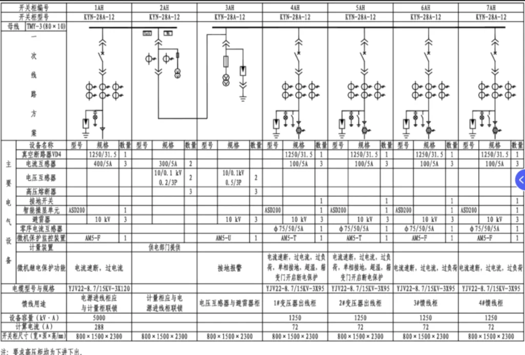
Protection allocation overview:
- Incoming feeder: Overcurrent, earth‑fault, directional‑overcurrent where applicable
- Power transformer: ANSI 87T differential main protection + overcurrent / REF backup protection
- Busbar: Bus differential protection for high‑speed bus‑fault clearance
- Outgoing feeders: 50/51 overcurrent and 50N/51N ground‑fault protection
- Global backup protection: Time‑graded upstream backup protection for all zones
Time‑current coordination study ensures that faults on outgoing feeders trip feeder‑relays first, without tripping transformer or incoming‑feeder protection.
Frequently Asked Questions About Protective Relaying
What is the basic principle of protective relaying?
Protective relaying measures electrical quantities (current, voltage, impedance, power). When measurements exceed pre‑calculated thresholds, relays issue trip commands to circuit breakers to isolate faulty equipment, balancing selectivity, speed, sensitivity and reliability.
What are the main types of protection relays?
Major categories of the electrical protective relay include overcurrent, earth‑fault, differential, distance, directional‑overcurrent, voltage‑frequency supervision, reverse‑power, and dedicated motor / transformer protection relays. Modern numerical electrical protective relay integrates multiple functions within one unit.
What is the difference between primary and backup protection?
Primary protection is the fastest‑acting main protection for a given equipment zone. Backup protection operates when primary protection fails, to avoid widespread blackouts.
How does a protection relay detect a fault?
Relays sample secondary‑side signals from CT and VT instrument transformers, compare measured values against setting thresholds, and execute internal protection algorithms to distinguish genuine faults from normal operating transients.
What is relay coordination?
Relay coordination means tuning pickup and time‑delay settings so that the relay nearest to fault trips first, while upstream backup relays trip only as a fallback. This guarantees selectivity and avoids cascading outages.
What are ANSI protection relay numbers?
ANSI / IEEE C37.2 defines standard numeric device codes for each protection function (e.g. 51 time‑overcurrent, 87 differential, 32 reverse‑power). These codes simplify documentation and cross‑vendor engineering communication.
What is the difference between numerical and electromechanical relays?
Electromechanical protective relays use moving mechanical components for fault detection. Numerical relays use microprocessors, deliver multi‑function protection, fault‑recording, digital‑communication and self‑diagnostic features, and are the standard for modern projects.
How often should protection relays be tested?
Commissioning tests are mandatory before energisation. Periodic in‑service testing intervals follow local utility codes or owner‑specification; typical industrial practice is 2‑5‑year secondary‑injection test cycles.
What standards apply to protection relays?
Primary international standards are IEC 60255 series for hardware and performance; ANSI/IEEE C37.2 for device‑numbering; IEC 61850 for substation communication.
How do you select a protection relay for a substation?
Start from project protection‑philosophy document and short‑circuit‑study results. Define required protection functions, CT/VT parameters, communication needs, environmental rating and standard compliance, then match hardware specifications.
What is the overall development direction of future protective relaying?
Future protective relaying will develop toward intelligence, digitization, networking and high reliability.
Conclusion
Within the digital protective relay market, protective relaying is not merely hardware‑product selection. Reliable power‑system protection comes from three pillars: sound protection‑principle understanding, correct site‑specific setting calculation, and rigorous commissioning and periodic testing.
Numerical multifunction protective relays deliver powerful capabilities, yet mis‑configuration or poor coordination can negate hardware performance. For EPC contractors and asset owners, investing in quality protection‑engineering design and proper commissioning lowers long‑term operational risk, reduces costly unplanned downtime and protects high‑value generation and industrial assets.
When you are specifying protection for your next substation, heavy‑industry or renewable‑energy project, work with experienced relay‑engineering resources to align hardware selection, protection philosophy and setting calculations to your exact site conditions.
Technical References & Source Documents
- IEEE C37.2‑2008, IEEE Standard for Electrical Power System Device Function Numbers, Acronyms, and Contact Designations
- IEC 60255‑1:2021, Measuring relays and protection equipment — Part 1: General requirements
- IEC 60255‑26:2025, Measuring relays and protection equipment — Part 26: Electromagnetic compatibility requirements for protection relays
- IEC 61850 series, Communication networks and systems for power‑utility automation
- IEEE Guide for Protective Relay Applications to Power System Buses (IEEE C37.97)
- IEEE Std 242‑2001, IEEE Recommended Practice for Protection and Coordination of Industrial and Commercial Power Systems



About Author

Hello, I'm Leno Zhang. I have 15 years of experience in the power relay protection industry with extensive pre-sales and after-sales project experience. Our company specializes in various complete sets of relay protection and automation equipment. I can assist customers in solving all practical on-site project challenges and provide optimal integrated solutions.
Tell Us Your Requirement
High Quality
Stable performance, reliable design, ensuring safe operation for power system protection and grid stability.
Fast Delivery
Timely delivery to support your urgent orders and project schedules efficiently and professionally at any time.
Best Warranty
Professional Warranty: Reliable after-sales support for stable relay protection and long-term customer satisfaction.