

-
Leon Zhang sales consultant
-
Email: zxl635973785@gmail.com
-
Phone/WhatsApp: +86 13655813266
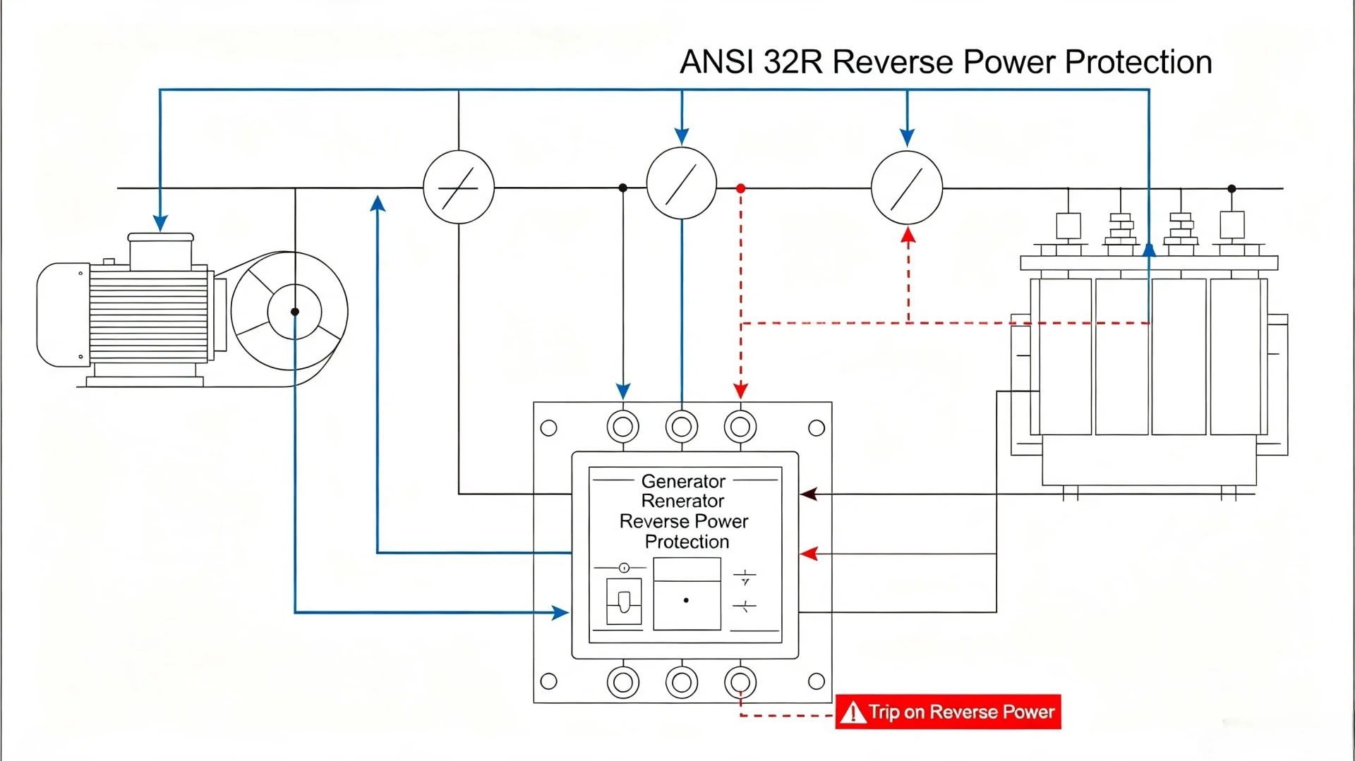
Generator Reverse Power Protection (ANSI 32): Settings and Testing
Generator reverse power protection is ANSI 32: a directional element that reads the sign of active power at a generator terminal and opens the breaker when the machine starts absorbing power instead of producing it. That condition is called motoring. The relay holds any negative reading for a set delay before it acts, because a few cycles of reversed power are normal during load transfer.
Why Generator Reverse Power Protection Is Important
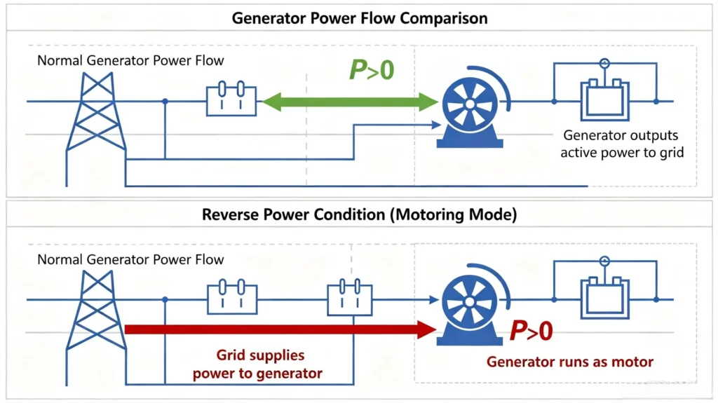
A synchronous generator needs two inputs to stay useful: mechanical power from the prime mover, and synchronism with the grid. Take the first one away and the machine stays tied to the system. It becomes a motor, drawing power from the grid to spin the turbine that used to drive it.
Motoring does not look like a fault to most of the panel. No overcurrent. No overvoltage. The stator current sits at the no-load value and the bus voltage stays inside limits. By the time a temperature alarm arrives, the turbine blades are already heating.
Motoring is quiet. That is the problem.
At a glance
- Device number. ANSI 32. On a generator it is written 32R, for reverse power, but it is one device number, not a second standard.
- What it measures. Active power P. Not current, not voltage. A directional overcurrent element cannot see this fault, because the current is ordinary load current.
- Pick-up. 1% to 5% of rated power on steam turbines, 5% to 15% on diesel units. Set it just above the machine no-load loss so healthy operation never reaches it.
- Delay. 2 s to 10 s in most plants. The short end rides out load transfer; the long end waits for the prime mover to actually stop turning.
- Trip logic. Two conditions, held at the same time: power below the pick-up setting, and that condition lasting longer than the delay.
- Top cause. CT polarity reversed at commissioning. Flip the CT and the element sees forward power while the machine is motoring, so nothing picks up.
- Not covered. It does not protect against motoring on an isolated bus with no grid to feed back from, and it does not detect under-frequency. Those are separate functions.
- Reference frame. IEEE C37.102-2023 governs generator-side practice. ANSI/IEEE C37.2-2008 defines the 32 number. IEC 60255-1:2022 covers the relay as a measuring device.
Where to Start, by Your Role
Three people touch the same element on the same panel, and they should not begin in the same place. This is the order we use on a site that has never had motoring protection before.
- Protection engineer. CT polarity first, pick-up second, delay third. The last two numbers are meaningless until the first one is right.
- EPC or design. Decide where reverse power is measured: generator breaker, unit transformer HV side, or the point of common coupling. That choice fixes how many CTs the panel carries.
- Plant owner. Start from the failure you have actually had. A generator that motored for ten minutes is a different budget conversation from a commissioning report the utility rejected.
- Commissioning tester. Run the operating-time test at the smallest pick-up and walk upward. One sequence covers polarity, pick-up and delay at the same time.
Number, not standard. ANSI 32 is a device number, not a published standard. The number comes from ANSI/IEEE C37.2-2008, the list of electrical power system device function numbers. Generator application sits in IEEE C37.102-2023, the Guide for AC Generator Protection. The relay itself is judged against IEC 60255-1:2022, and station-layer communication follows IEC 61850.
You will see 32R, 32F and plain 32 on drawings. 32R marks the reverse direction, 32F the forward one, and the bare 32 is the family. All three are device numbers from C37.2, and none of them has a standard of its own.
What Is Generator Reverse Power Protection?
Generator reverse power protection is a directional power function on a synchronous machine. It measures active power at the generator terminals and compares its sign against a pick-up value. When the sign turns negative and stays negative, the relay alarms or trips the generator breaker. The machine stops motoring before the prime mover takes any real damage.
Normal vs Fault Operating State
Healthy operation and motoring differ by one sign. The wiring on both sides is identical.
- Normal state. The prime mover supplies mechanical power, the generator pushes active power out to the grid, and mechanical input exceeds electrical output.
- Fault state. The prime mover loses drive, the grid feeds the machine, and that machine drives the prime mover as a motor.
The machine does not care which way the power moved. The turbine does.
Core Protection Functions
Four jobs, in this order, and the element cannot skip any of them.
- Track generator active power and its direction in real time.
- Recognise the reversed condition against the pick-up setting.
- Hold the condition for the delay setting before issuing a trip.
- Open the generator breaker so the prime mover stops being dragged.
Causes of Reverse Power in Generators
Reverse power is a symptom. The element trips, but the event happened somewhere else, usually upstream of the relay. The three groups below cover nearly every case we have been called out to look at.
Loss of Prime Mover Input (Main Cause)
The prime mover stops delivering torque while the machine stays synchronised. This is the common one.
- Steam turbine. A valve shuts or the steam supply drops. A closed governor valve on a running turbine is the single most frequent trigger on a thermal unit.
- Hydraulic turbine. Water flow collapses or the wicket gates close. The unit then runs as a pump, which is the hydropower version of motoring.
- Diesel generator. Fuel fault, flameout, or a speed governor that has lost its output. The engine is still coupled to a machine that is now driving it.
Governor valves close. On a thermal unit that is usually the whole story.
Generator Operating Errors
Operator and control mistakes that put the machine into reverse without any hardware fault.
- Incorrect synchronising, closing the breaker outside the permitted slip window.
- Unbalanced load sharing when two units run in parallel, one of them taking less than its share.
- Unit control parameters set for a machine that is being replaced by a smaller one.
Grid and System Disturbances
The grid side. These usually clear themselves, which is why the delay setting has to exist.
- Large load rejection elsewhere on the network, causing a generation surplus that flows back into running units.
- Grid frequency and voltage excursions that push the machine toward its reactive limits.
- Short-term system instability, where the power swing crosses zero for a couple of cycles.
How Does Generator Reverse Power Protection Work?
Reverse Power Protection Relay Measuring Principle
The relay takes three-phase voltage from the PT and three-phase current from the CT, then computes active power. Industrial numerical relays use this form:
P = √3 × U × I × cosφ
The sign of the result is what matters. Phase angle alone is not the test, and that trips people up. cosφ flips sign when you reverse the current reference, and CT polarity is a wiring choice. A relay wired with reversed CTs will report forward power while the generator is visibly motoring.
So the practical rule is: read P, read its sign against the relay terminal convention, and hold the negative value. If the convention is set for the generator terminal, P below zero means the machine is taking power from the system.
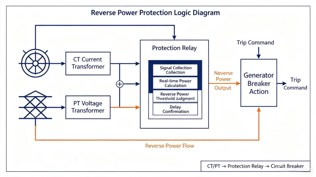
Reverse Power Protection Logic Diagram
Six steps, and each one is a separate setting or wiring check on the panel.
- Signal collection from CT and PT.
- Real-time active power calculation.
- Comparison against the pick-up setting.
- Delay confirmation, started the moment the condition appears.
- Trip or alarm command output.
- Generator breaker opening.
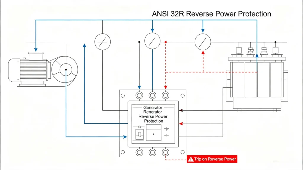
ANSI 32 Reverse Power Protection Relay Function
The ANSI device numbering scheme gives every protection function a fixed number so drawings, specs and PLC tags agree across vendors. 32 is directional power. On a generator, the reverse variant is written 32R.
| ANSI Code | Standard Function Definition | Application Scenario |
|---|---|---|
| 32 | Directional Power Relay | General directional power monitoring |
| 32R | Reverse Power Protection | Generator anti-motoring core protection |
| 32F | Forward Power Protection | Prevent excessive forward power output. |
A modern numeric generator protection relay carries 32R alongside overcurrent, earth fault, under and over voltage, and frequency functions on one device. That integration is what keeps the panel small and the wiring short. It does not remove the need to check each function separately at commissioning.
Generator Reverse Power Protection Setting Calculation
Settings are where this function earns or loses its reputation. Too sensitive and the plant trips on every load transfer. Too blind and the turbine cooks. The two values below, pick-up and delay, carry most of the risk.
Reverse Power Pickup Setting
Pick-up is set against the machine no-load loss, not against its rating. A generator that idle-draws 3% of rating needs a setting above 3%, or it will trip on its own fluctuations.
- Steam turbine generator. 1% to 5% of rated power. Low no-load loss, so the setting sits low and the accuracy demand goes up with it.
- Diesel generator. 5% to 15% of rated power. A diesel idling has a much larger internal loss, so the pick-up has to sit higher.
- Hydro generator. 2% to 8% of rated power, and a pumped unit is designed to run backward, so the intent has to be checked against the pumping mode.
- Worked example. A 10 MW steam turbine with a no-load loss of 380 kW. Set the pick-up at 5% of rating: 0.05 × 10 MW = 500 kW. That 500 kW becomes the reverse power trip threshold.
Start from the measured idle draw, not from the rating.
Time Delay Setting
The delay is what separates a transient from a fault. Power crosses zero every time load transfers or the grid swings, and a few cycles of reversed power there is not a fault.
- 2 s–3 s. Short. Used where a motoring event has to be cleared fast, typically on large steam turbines where blade heating starts quickly.
- 5 s–10 s. Long. Used on complex or weak grid connections where the direction genuinely flips during switching.
- Below 2 s. Only with direction logic verified in the field. A short delay on a badly polarised CT is how healthy plants end up tripping themselves.
The delay is the whole argument about this setting.
Key Setting Influencing Factors
Four inputs go into the two numbers above. They are not independent.
- Generator type and the prime mover behind it.
- Grid connection mode, and the on-site load profile during transfer.
- The manufacturer factory data and type test report.
- Plant class and the grid code requirements for the connection.

Reverse Power Protection for Different Generator Types
Steam Turbine Generator (Thermal Power Plant)
Steam turbines have very low no-load loss and very little tolerance for running backward. Blade overheating, steam erosion and rotor heating follow quickly.
Reverse power protection is a primary requirement here, not a backup. The pick-up runs at the low end of the range and the delay is short, because the machine cannot afford a long motoring window.
Blades first, then the rotor.
Diesel Generator (Industrial/Marine/Backup)
These sit in factory backup sets, marine plants and distributed generation, and they are usually the units running in parallel. Reverse power between parallel diesel sets is common.
The damage here is mechanical wear on the engine while it idles, plus the loading already carried by the unit that stayed healthy. Pick-up sits higher to clear the engine idle loss, and the delay can be longer.
Parallel sets are where this happens.
Hydro Generator (Hydropower Station)
When the turbine loses water and the generator drives it, the unit runs in a pumping state and the hydraulic system takes the shock.
Set the pick-up from the pump-mode commitment in the unit operating procedure. A unit that is meant to pump needs that mode excluded from the trip logic, or it will trip itself every time the schedule calls for pumping.
Check the pumping mode before setting anything.
Reverse Power Protection Scheme in Power Plants
Four devices, one loop. The relay is only doing the deciding.
System Core Components
- CT and PT: Carry the measured current and voltage to the relay, and decide the polarity reference everything else depends on.
- Protection relay. Compute power, apply the pick-up and delay logic, and output the trip.
- Generator circuit breaker. Do the actual opening. No relay trips a breaker that has a stalled trip coil.
- SCADA or DCS. Record the event, so the cause is visible after the fact.
That recording is worth as much as the trip itself. Without it, the shift looking at the panel sees a breaker open and no reason for it.
Difference Between Reverse Power Protection and Other Generator Protections
On site, reverse power protection gets confused with the current-based functions next to it. The criterion is different, so is the fault it catches.
| Protection Type | Core Detection Criterion | Applicable Fault Scenario |
|---|---|---|
| Reverse Power Protection (ANSI 32R) | Power flow direction & reverse power value | Generator motoring operation |
| Overcurrent Protection | Current magnitude exceeding threshold | Short circuit, overload fault |
| Differential Protection | Current difference between two ends of generator | Generator internal winding short circuit |
| Under Voltage Protection | Bus voltage drop exceeding limit | Grid voltage abnormality. |
The short version: reverse power faults carry no overcurrent and no overvoltage. Conventional protection cannot replace ANSI 32R, and ANSI 32R cannot replace differential protection.
- Differential. Internal winding faults. It will never see motoring.
- Overcurrent. Short circuits and overload. Load current during motoring is below the pick-up.
- Under voltage. Bus conditions. It says nothing about which way power is moving.
How to Test Reverse Power Protection?
Commissioning testing proves the loop end to end. A settings sheet that nobody has verified is a guess with a stamp on it.
Required Testing Equipment
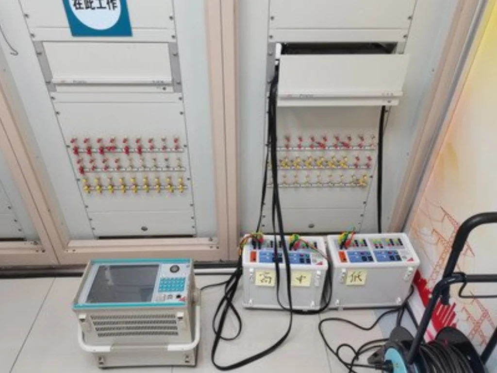
- Three-phase relay protection test set, a secondary injection tester.
- High precision signal simulation source for voltage and current.
- Parameter recording tool for the commissioning report.
Standard Testing Procedure
Six steps. Run them in this order.
- Read back the stored settings and confirm them against the specification sheet.
- Inject three-phase voltage and current, and check the reported power value.
- Sweep the current phase angle to find the actual pick-up, and compare it with the setting.
- Hold the reverse condition for a period shorter than the delay, and confirm no trip.
- Hold it longer than the delay, and confirm the trip output energises.
- Verify the breaker trip coil, then record the results.
Step three is the one that catches a reversed CT. Sweeping the angle also shows where the sign changes, so a polarity error shows up as a measurement error before it becomes a nuisance trip.
Sweep the angle. One test point proves nothing.
Common Problems During Reverse Power Protection Commissioning
Two failure modes account for most callouts. One trips when it should not, the other stays quiet when it should not.
One trips when it should not. The other stays quiet when it should not.
False Reverse Power Trips
The element fires on a healthy machine. Fix the wiring and the setting before touching the hardware.
- Causes: CT polarity reversed, phase sequence wrong, pick-up set below the no-load loss, CT accuracy below Class 0.5.
- Fixes: recheck the polarity and phase rotation, raise the pick-up above the measured idle draw, replace or recertify the CTs.
Protection Refusal to Trip
The element stays silent while the machine motors. This one is more expensive.
- Causes: the function disabled in the settings, direction logic set for the wrong reference, or an incomplete signal loop.
- Fixes: enable the 32R function, recalibrate the direction reference against the measured power, and trace the secondary wiring.
Industry Standards for Generator Reverse Power Protection
Scheme design, setting practice and equipment selection all sit under these. The list is short, and each one does a different job.
- IEC 60255-1:2022. Measuring relays and protection equipment, common requirements. This is what the relay as a hardware device is tested against.
- IEC 61850. Substation automation communication. It governs how the relay talks to the station layer, not how the protection logic behaves.
- IEEE C37.102-2023. The AC generator protection guide. This is the one that covers motoring protection, and it is where the setting philosophy comes from.
- ANSI/IEEE C37.2-2008. Device function numbers, including 32, 32R and 32F.
- IEEE 1547-2018. Distributed resource interconnection. Relevant where the generator sits behind an interconnection rather than a generator breaker.
How to Select a Reliable Generator Reverse Power Relay Supplier?
For an EPC contractor or a plant owner, the relay decides how the generator behaves on its worst day. Three criteria carry the weight.
Complete Protection Functions
One device should carry 32R together with overcurrent, earth fault, frequency and voltage. Split functions across boxes means more wiring and more places to get polarity wrong.
Professional Technical Performance
Accuracy on the power calculation is the product that matters, since the whole function rests on the sign. Check the measurement accuracy, the CT and PT ratio handling, and whether the device supports steam, diesel and hydro machines of different sizes without a firmware change.
Complete After-Sales Support
Setting calculations, on-site commissioning guidance, remote support and English documentation. On an overseas project the commissioning window is short, and the team on site is not going to reverse-engineer a setting philosophy at two in the morning.
FAQ About Generator Reverse Power Protection
Q1: What is Reverse Power Protection of Generator?
It is the ANSI 32R directional function on a generator that watches the sign of active power. When the machine starts absorbing power from the system, the relay opens the generator breaker to stop it motoring and protect the prime mover.
Q2: What ANSI code is reverse power protection?
The device number is ANSI 32, written 32R when the reverse direction is the one in question. It comes from ANSI/IEEE C37.2-2008. It is a device number, not a standard, so no one publishes a “32R standard”.
Q3: What causes reverse power in generators?
Loss of prime mover drive is the main one: a shut steam valve, lost water flow, or a diesel flameout. Operator error, uneven load sharing between parallel units and grid disturbances also do it.
Q4: What is the typical reverse power relay setting?
Steam turbine generators take 1% to 5% of rated power, diesel generators 5% to 15%, and hydro units roughly 2% to 8%. Delay normally lands between 2 s and 10 s, with the short end for fast-clearing steam turbines and the long end for weak grid connections.
Q5: Can reverse power protection prevent generator damage?
Yes, for this fault and this fault only. It is the dedicated protection against motoring, so it avoids turbine blade overheating, engine wear while idling and the hydraulic shock on a pumped hydro unit. It does not cover electrical faults.
Q6: How do you test a reverse power relay?
Inject three-phase voltage and current with a secondary injection set, sweep the phase angle to measure the real pick-up, confirm the element holds below the delay and trips above it, then verify the breaker trip. Record the results for the commissioning report.
Conclusion
Generator reverse power protection is the only element that answers the question “is this machine producing or consuming power”. Everything else on the panel answers a different question, which is why the function cannot be dropped from a specification to save cost.
Get the two settings right and the element stays quiet for years. Get CT polarity wrong and it either trips a healthy generator or ignores a motoring one. The wiring check comes before the number work, and the test sweep catches both.
Polarity first, always. The numbers come after.
Technical Reference
- IEC 60255-1:2022. Measuring relays and protection equipment, common requirements.
- IEEE C37.102-2023. IEEE Guide for AC Generator Protection.
- ANSI/IEEE C37.2-2008. Standard Device Numbers for Power System Protection Relays.
- IEEE 1547-2018. IEEE Standard for Interconnection and Coordination of Electric Energy Systems with Distributed Resources.
- IEC 61850. Communication networks and systems for power utility automation.
- Older references. Application notes still in circulation cite IEC 60255-1:2009 and IEEE C37.102-2006. Both have been superseded. IEC 60255-1:2022 and IEEE C37.102-2023 are the current editions.
Related Reading
- Generator protection relay: the panel this element sits in
- Reverse power flow protection: the same element on a line or bus
- ANSI 32 reverse power protection relay: hardware and rating data
- Generator protection relays: the full range
- Earth fault protection: what sits beside ANSI 32 on the panel
- Frequency protection: the other generator-side function
- Short circuit protection relay: overcurrent practice
- Differential protection: generator internal faults



About Author

Hello, I'm Leno Zhang. I have 15 years of experience in the power relay protection industry with extensive pre-sales and after-sales project experience. Our company specializes in various complete sets of relay protection and automation equipment. I can assist customers in solving all practical on-site project challenges and provide optimal integrated solutions.
Tell Us Your Requirement
High Quality
Stable performance, reliable design, ensuring safe operation for power system protection and grid stability.
Fast Delivery
Timely delivery to support your urgent orders and project schedules efficiently and professionally at any time.
Best Warranty
Professional Warranty: Reliable after-sales support for stable relay protection and long-term customer satisfaction.