

-
Leon Zhang sales consultant
-
Email: zxl635973785@gmail.com
-
Phone/WhatsApp: +86 13655813266
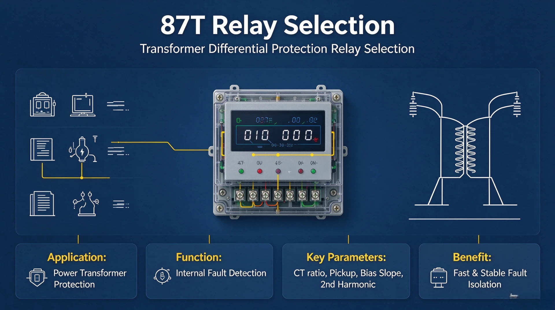
How to Select an 87T Relay for Transformer Differential Protection
87T relay selection starts with the transformer, not the relay. Fix rated power, voltage ratio, vector group, CT data and the protection functions the scheme must deliver, then match a relay that covers those numbers.
Transformer differential relay selection is mostly a comparison exercise. A numerical 87T relay may also carry restricted earth fault, overcurrent, event recording and substation communication, so two relays with the same differential element can differ widely on everything the project actually needs.
This guide covers how to select an 87T relay in the order the criteria are usually checked, then the comparison tables and the RFQ checklist you can send to a supplier.
Design reviews rarely fail on the relay model. They fail on missing CT data.
Written by Leon Zhang, Protection Application Engineer · Technical review by Li Ming, Electrical Engineer · Last reviewed September 2026
What Is a Differential Relay for Transformer Protection?
What Is an 87T Differential Relay?
An 87T differential relay monitors the balance of current entering and leaving a transformer. Under normal and external fault conditions, currents remain balanced. When an internal fault occurs, the balance is disrupted and the relay trips. The “87T” designation refers to transformer differential protection under ANSI/IEC standards.
What Faults Does It Detect?
The relay detects internal faults within the transformer protection zone, including:
- Phase-to-phase and phase-to-ground faults
- Winding faults (including turn-to-turn faults)
- Internal lead and terminal faults
Detection speed and sensitivity depend on relay settings, CT performance, and protection scheme configuration.
Where Is the Differential Protection Zone?
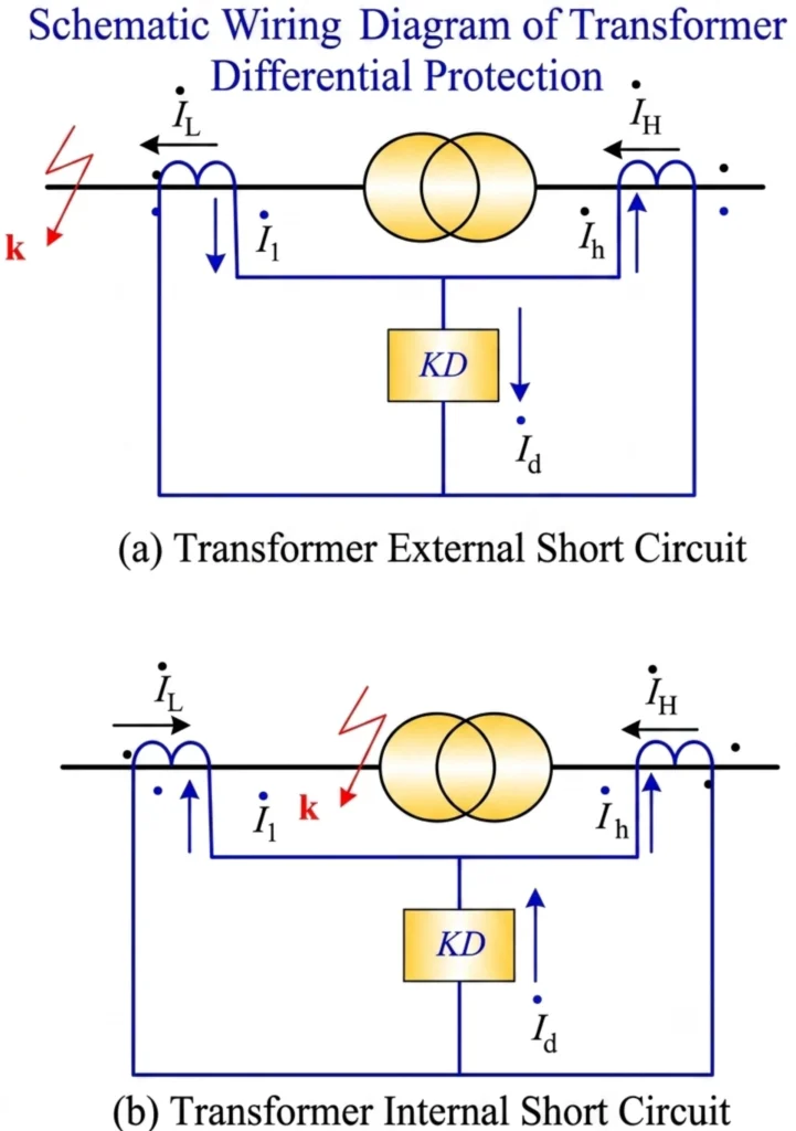
The zone is defined by CT locations on each side of the transformer, covering windings and internal connections. Faults inside the zone cause tripping; faults outside are restrained. This provides fast, selective protection for the power transformer differential relay system.
For a detailed explanation, see our Transformer Differential Protection Working Principle guide.
Key Selection Criteria for a Transformer Differential Relay
87T relay selection runs through nine inputs. Work them in this order and the shortlist falls out of the data. Skip one and the error usually surfaces at commissioning instead.
1. Transformer Rated Power
When selecting an 87T relay, the following transformer rating information is required:
- MVA rating
- HV voltage
- LV voltage
- Frequency
- Number of windings (two-winding or three-winding)
These parameters determine the protection range, CT requirements, and relay configuration, which are core to transformer protection relay selection.
2. Transformer Voltage Ratio
The relay must accommodate the HV/LV current relationship and CT ratios. The voltage ratio defines the current relationship between both sides and influences CT selection and relay compensation settings.
For detailed calculation methods, see our Differential Protection Relay Setting Calculation guide.
3. Transformer Vector Group
The vector group defines the phase displacement between HV and LV windings. The relay must support the required vector group compensation for correct differential current calculation of the numerical transformer differential relay.
Common vector groups include:
- Dyn11
- Yd1
- Yd11
- Yy0
For detailed application guidance, see our Star-Delta Transformer Differential Protection and Star-Star Transformer Differential Protection guides.
4. CT Parameters
CT data constrains transformer differential relay selection more than any other input. Five parameters decide whether the scheme will balance:
- CT ratio – Must match the transformer primary currents on each side
- CT secondary rating – Typically 1A or 5A, must be compatible with relay inputs
- CT accuracy class – Affects protection reliability during high fault currents
- CT knee-point voltage – Determines CT performance under fault conditions and saturation resistance
- CT burden – Must be compatible with relay input impedance and wiring length
5. Protection Functions Required
In addition to 87T differential protection, the relay may need to support:
- Restricted earth fault (REF) – For enhanced ground fault protection
- Overcurrent protection (50/51) – Backup protection for phase and ground faults
- Thermal overload protection – For transformer thermal monitoring
- Breaker failure protection – For backup tripping if the circuit breaker fails to open
The required functions depend on the application, project specifications, and protection philosophy for transformer differential protection relay deployment.
6. Harmonic Restraint and Inrush Blocking
Harmonic restraint decides whether the relay survives the first energization. Saturation of the core during inrush produces a large differential current that looks like an internal fault. When selecting, confirm three things:
- Second harmonic restraint – The primary blocking method, adjustable over a relay-specific ratio range
- Fifth harmonic restraint – Used for overexcitation detection, model-dependent
- Cross-blocking – Restrains all three phases when inrush is detected on any one. Presence depends on the model.
A threshold set too low blocks a genuine internal fault during energization. Set too high, it trips on every energization. Ask the supplier for the adjustable range, not just for the presence of the function.
7. Communication and Integration
For substation automation and remote monitoring, the relay should support:
- IEC 61850 – Including GOOSE and MMS for digital substation integration
- Modbus RTU/TCP – For SCADA integration and legacy system compatibility
- IEC 60870-5-103 – For protection device communication (where applicable)
- Time synchronization – IRIG-B or SNTP for accurate event time-stamping
Select protocols based on project requirements and existing substation infrastructure.
8. Environmental and Mechanical Requirements
The relay must be suitable for the installation environment:
- Operating temperature range – Must match site ambient conditions
- Mounting type – Panel mounting, rack mounting, or DIN-rail (depending on relay form factor)
- Protection class – IP rating for dust and moisture protection
- Power supply – DC or AC voltage compatible with station battery or auxiliary supply
- Certifications – Compliance with utility, industry, or EPC project standards
9. Event Recording and Diagnostics
Fault recording is not the deciding line in 87T relay selection, but it is the item most often added late. Check for:
- Fault recording – Waveform capture in COMTRADE format
- Sequence of events (SOE) – Time-stamped event logging
- Disturbance records – Pre- and post-fault data for fault analysis
- Self-diagnostics – Relay health monitoring and alarm functions
These features simplify troubleshooting and reduce outage time.
Essential Protection Functions to Consider
The table below is the function set we normally specify where one relay has to cover more than the differential element.
| Function | Purpose |
|---|---|
| 87T | Transformer differential protection |
| 64REF / 87N | Restricted earth fault, where applicable |
| 50/51 | Overcurrent backup |
| 50N/51N | Earth-fault backup |
| 24 | Overexcitation |
| 49 | Thermal overload |
| 50BF | Breaker failure |
| 86 | Lockout logic |
| Fault recorder | Post-fault analysis |
Differential Characteristic and Percentage Bias
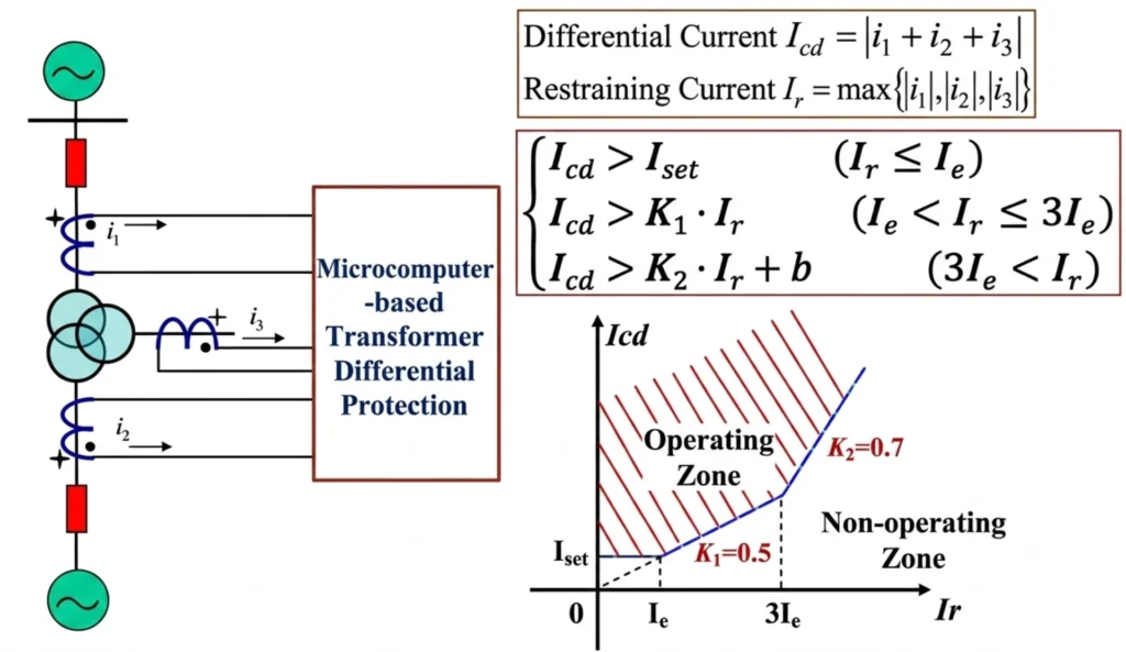
Percentage bias raises the relay’s operating threshold as through-current increases, ensuring stability during external faults while maintaining sensitivity for internal faults, which is a core performance indicator for transformer 87T relay selection.
A single-slope characteristic applies one constant bias across the entire range, while dual-slope uses a lower slope for the low-current region to preserve sensitivity and a higher slope for the high-current region to improve stability during severe external faults and CT saturation.
The percentage bias characteristic ensures the relay remains stable during external faults and CT saturation by raising the operating threshold proportionally to fault current.
Actual slope and pickup settings come out of the protection study, based on CT characteristics, transformer impedance, fault levels and relay type. The datasheet only tells you the range the relay can accept.
Harmonic Restraint: What to Confirm in the Datasheet
Once the relay passes the blocking-method check, four datasheet entries decide whether it fits the project.
- Overexcitation detection – Some relays add fifth harmonic or a flux-based algorithm. Availability is model-dependent, and it matters wherever overexcitation is a design case.
- Harmonic measurement – The relay derives harmonic content from digitized samples. Its sampling rate and filtering set how reliably it separates inrush from fault current.
- Inrush discrimination – Beyond harmonic analysis, some models add cross-blocking or waveform-shape criteria. Ask which method the model uses.
- Adjustable thresholds – A fixed threshold cannot cover every transformer and system condition. Confirm the range and the step size.
Harmonic Logic Is Manufacturer-Specific
The algorithm and the default thresholds come from the relay manufacturer, not from a single industry table. Two relays carrying the same 87T function may block at different second-harmonic ratios. Take the range from the manual of the exact model you are specifying, and record it on the comparison sheet.
Communication and Substation Integration
| Requirement | What to Check |
|---|---|
| IEC 61850 | MMS / GOOSE support |
| Modbus | SCADA integration |
| IEC 60870-5-103 | Legacy substation communication |
| Ethernet | Engineering / communication |
| GOOSE | Fast interlocking/tripping |
| Fault records | COMTRADE or equivalent |
| Time synchronization | IRIG-B / SNTP / PTP, if required |
Two-Winding vs Three-Winding 87T Relay Comparison
The winding count fixes the number of CT inputs and the compensation the relay has to run. 87T relay selection for a three-winding unit means a relay that accepts three-winding transformer differential protection inputs, or two separate relays with external summation. The table below is the comparison we send with a quotation.
| Item | Two-Winding | Three-Winding |
|---|---|---|
| CT inputs | HV + LV | HV + MV + LV |
| Differential elements | Two-side | Multi-side |
| Vector compensation | Required | Required for each winding |
| Application | Standard power transformer | Three-winding transformer |
| Relay selection | 2-winding 87T | 3-winding 87T |
Special Transformer Applications
Settings and relay configuration change with the transformer type. The five cases below cover most of what differs in practice.
Two-Winding Transformer
A two-winding transformer has one primary and one secondary winding. Differential protection compares currents from CTs installed on both sides. This is the simplest configuration and the most common for differential relay application. Setting calculations are straightforward, requiring compensation for CT ratio, voltage ratio, and vector group.
Three-Winding Transformer
A three-winding transformer has three separate windings, typically a primary and two secondary windings, or two primary windings and one secondary. Differential protection for three-winding transformers requires CTs on all three sides. The relay must compare currents from three sets of CTs, requiring more complex compensation and setting calculations. The differential current is the vector sum of all three winding currents. Some relays offer dedicated three-winding differential protection functions.
Auto-Transformer
An auto-transformer has a single continuous winding with a tap, providing a galvanic connection between HV and LV circuits. Differential protection for auto-transformers must account for the electrical connection between windings and the distribution of currents across the series and common windings. CT placement and compensation settings are more complex than for two-winding transformers. Some relays provide specific auto-transformer compensation algorithms.
Generator Step-Up Transformer
A generator step-up transformer carries the heaviest through-fault current in the plant, because the generator keeps feeding the fault after the grid side has tripped. Selection here turns on CT saturation margin and on coordination with the generator differential element. Where the two zones overlap, the settings have to be studied together. For the current balance inside the relay, see the transformer differential protection working principle.
Industrial Transformer
Industrial transformers supply power to manufacturing plants, processing facilities, and large loads. Differential protection for industrial transformers may require integration with process protection, coordination with motor protection, and trip settings for high inrush applications. Space constraints and panel layout considerations may also influence relay selection. Communication interfaces should be compatible with plant SCADA or DCS systems.
High-Impedance vs Low-Impedance Differential Protection
| Feature | High Impedance | Low Impedance |
|---|---|---|
| CT matching | Strict | More flexible |
| Configuration | Hardware-oriented | Digital / configurable |
| Application | Traditional schemes | Modern numerical schemes |
| CT saturation stability | Strong stability | Managed by restraint / algorithms |
| Engineering flexibility | Lower | Higher |
High-impedance differential protection uses a high-value series resistor in the relay circuit to force current through the CTs during external faults, ensuring stability even when CT saturation occurs. It requires careful CT matching and is typically applied for busbar or restricted earth fault protection.
Low-impedance differential protection is commonly used in numerical relays. It relies on software-based percentage bias characteristics and digital signal processing to maintain stability. This approach offers greater flexibility, simpler CT requirements, and easier integration with other protection functions.
Choosing Between the Two Schemes
Most numerical 87T relays use the low-impedance percentage-biased scheme. High-impedance schemes still appear where the CT circuits are short, the CTs are matched, and the zone is a restricted earth fault or busbar zone rather than a transformer winding. The choice follows CT performance and the existing protection philosophy, not relay availability.
Interoperability and Retrofit Considerations
Retrofit work is where transformer differential relay selection fails most often, because the panel, the CT ratings and the SCADA interface are already fixed. Check compatibility before the offer, not after delivery.
- CT Input Compatibility – Confirm CT secondary rating (1A or 5A) matches the new relay inputs.
- Binary Inputs and Outputs – Verify number and type of I/O meet existing scheme requirements.
- Communication – Supported protocols and physical interfaces match the existing SCADA or substation automation system.
- IEC 61850 – GOOSE and MMS support for digital substation integration, where the project is IEC 61850 based.
- Existing Protection Scheme – Review coordination with backup protection, interlocking, and scheme-specific logic.
- Panel Dimensions – Check that the new relay fits within the available panel space.
- Wiring – Review terminal assignments and wiring compatibility; update documentation as needed.
- Settings Migration – Translate existing settings to the new relay format using manual or manufacturer tools.
- FAT and SAT – Plan factory and site acceptance testing to verify configuration, installation, and system integration.
Testing Requirements Before Commissioning
Testing is not a selection criterion, but the test plan a supplier can support is a common tie-breaker in 87T relay selection. Before energization, these items have to be verified:
- CT polarity – Confirm correct phase relationship between primary and secondary currents
- CT ratio – Verify that CT ratios match nameplate ratings and relay settings
- Relay input – Check that analog inputs are correctly connected and scaled
- Differential characteristic – Verify pickup and slope settings using secondary injection
- Trip logic – Confirm trip contacts and alarm outputs operate as configured
- Binary I/O – Verify correct mapping and response of all binary inputs and outputs
- Communication – Check protocol settings and data exchange with SCADA or substation automation systems
- Event recording – Confirm fault recording and waveform capture functions operate correctly
- Protection settings – Review all settings against the approved calculation and design documentation
Record the results against the approved setting sheet, not against the relay defaults. Secondary injection covers the differential characteristic; primary injection is the only way to confirm CT polarity and ratio end to end.
👉 Full 87T testing and commissioning procedure →
Transformer Differential Relay RFQ Checklist
Send these entries with the enquiry. Missing rows usually delay the offer rather than change the model.
| Information | Required |
|---|---|
| Transformer capacity | MVA |
| HV voltage | kV |
| LV voltage | kV |
| Transformer vector group | e.g. Dyn11 |
| Number of windings | 2 / 3 |
| CT ratios | HV / LV / MV |
| CT secondary | 1A / 5A |
| Frequency | 50 / 60 Hz |
| Differential function | 87T |
| REF | Required / Optional |
| Communication | IEC 61850 / Modbus / etc. |
| Binary I/O | Project requirement |
| Fault recording | Required / Optional |
| Installation | Panel / rack |
| Auxiliary supply | DC voltage |
| Applicable standards | Project specification |
Questions to Ask Before Buying an 87T Differential Relay
These are the questions we ask before quoting an 87T relay. They are also the ones that overturn 87T relay selection late in a project, after the design has already been frozen:
- Does the relay support my transformer vector group (e.g., Yd11, Dyn11, Yy0)?
- What CT ratios are supported, and does the relay provide internal CT ratio compensation?
- Does the relay provide internal vector compensation, or are external CT connections required?
- Does it support both 1 A and 5 A CT secondary inputs?
- What differential characteristic is used (single slope, dual slope, or adaptive)?
- How is transformer inrush detected and restrained (e.g., second harmonic, cross-blocking)?
- Does the relay support IEC 61850 communication protocols?
- Does it provide GOOSE messaging for fast peer-to-peer communication?
- Can it record COMTRADE fault files for post-event analysis?
- What FAT (Factory Acceptance Test) documents are provided with the relay?
- Is factory testing available before shipment?
- Can the relay be customized to meet specific EPC project requirements (e.g., labelling, logic, protocol configuration)?
Recommended 87T Transformer Differential Protection Relay
For a two-winding transformer, start from the 87T relay specification: percentage-biased differential element, harmonic inrush restraint, internal vector group compensation, 1 A and 5 A CT inputs. For a three-winding transformer, compare the same list against the three-winding transformer differential protection relay, which adds the third current input and per-winding compensation.
87T Relay Specification: Key Features to Compare
- CT Inputs – Supports both 1A and 5A CT secondary inputs with configurable ratio compensation
- Vector Group Compensation – Internal software compensation for common vector groups including Yd11, Dyn11, Yy0 and others
- Protection Functions – Percentage-biased differential protection with single or dual-slope characteristic, harmonic restraint for inrush blocking, and optional backup functions
- Communication Options – IEC 61850 with GOOSE and MMS, Modbus RTU/TCP, IEC 60870-5-103
- Event Recording – COMTRADE fault recording and sequence of events for post-event analysis
- Configuration Flexibility – Adjustable settings to match project-specific transformer and CT parameters
87T Differential Relay Selection – Q&A
Q1. What is a differential relay for transformer protection?
A differential relay for transformer protection is a device that compares currents entering and leaving a transformer. Under normal and external fault conditions, currents are balanced. When an internal fault occurs, an imbalance is created and the relay issues a trip signal.
Q2. What is an 87T differential relay?
The 87T differential relay is the ANSI/IEC designated protection function for transformer differential protection. “87” denotes differential protection, and “T” indicates application to a transformer. Modern 87T relays are numerical devices with advanced compensation, communication and recording features.
Q3. What information is required to select a transformer differential relay?
You will need transformer MVA rating, HV and LV voltages, vector group, number of windings, CT ratios and secondary ratings, required protection functions, communication protocols, and project standards.
Q4. Does an 87T relay support Dyn11 transformers?
Yes. Numerical 87T relays typically provide configurable vector group compensation, including support for Dyn11 and other common vector groups such as Yd11, Yd1, and Yy0.
Q5. What CT parameters should be checked before selecting an 87T relay?
Check CT ratio, secondary current rating (1A or 5A), accuracy class, knee-point voltage, and burden compatibility with relay inputs and wiring.
Q6. Should I choose a two-winding or three-winding differential relay?
This depends on your transformer configuration. Two-winding relays are suitable for two-winding transformers. Three-winding relays are required for three-winding transformers and provide compensation for currents from all three sides.
Q7. Does a numerical 87T relay provide internal vector compensation?
Yes. Numerical 87T relays perform vector group compensation internally through software configuration, eliminating the need for external CT connection adjustments.
Q8. What communication protocols should a transformer differential relay support?
Common protocols include IEC 61850 (GOOSE and MMS), Modbus RTU/TCP, and IEC 60870-5-103. Protocol selection depends on substation automation and SCADA integration requirements.
Q9. What additional protection functions should an 87T relay provide?
Optional functions may include restricted earth fault (REF), overcurrent protection (50/51), thermal overload protection, and breaker failure protection, depending on application requirements.
Q10. What testing is required before commissioning an 87T relay?
Testing includes CT polarity and ratio checks, secondary injection tests for pickup and slope, harmonic restraint verification, trip logic checks, binary I/O verification, and primary injection tests for full system validation.
Q11. What documents should be requested from the relay supplier?
Request FAT (Factory Acceptance Test) reports, test certificates, configuration files, wiring diagrams, communication setup guides, and the relay manual with setting instructions.
Q12. Can an 87T relay be used for transformer retrofit projects?
Yes. Numerical 87T relays are suitable for retrofit projects. Compatibility should be checked for CT inputs, binary I/O, panel dimensions, wiring, communication, and protection scheme integration.
Conclusion
87T relay selection is decided by the transformer data, not by the catalogue. Match the relay to the winding count and the CT inputs first. Confirm the harmonic restraint method and its adjustable range second. Then check communication, the test plan and the documents the supplier will hand over.
Two gaps cause the most rework on site: a relay whose CT ratio compensation range cannot cover the HV/LV mismatch, and a vector group the firmware does not support. Both are answerable from the datasheet before the order is placed. Ask for the range, not for a yes.
For the current balance behind the differential element, start with the transformer differential protection working principle. The wider scheme, beyond 87T, is covered in our transformer protection relay selection guide.
Reference Technical Documents & Standards
| Source | What it covers | Type | Edition |
|---|---|---|---|
| IEEE C37.91 | Guide for protecting power transformers: protection philosophy, CT behaviour during faults, 87T application | IEEE guide | 2021 |
| IEEE C37.2 | Device function numbers and acronyms; defines the 87T designation | IEEE standard | 2022 |
| IEC 60255-1 | Common requirements for measuring relays and protection equipment: type tests, environmental conditions | IEC standard | 2022 |
| IEC 60076-1 | Power transformers, Part 1: General; ratings, connection phase displacement symbols, tolerances | IEC standard | 2011 |
| IEC 61850-8-1 | MMS and GOOSE mapping for substation communication | IEC standard | 2011+A1:2020 |
| IEC 61850-9-2 | Sampled values over the process bus | IEC standard | 2011+AMD1:2020 |
| IEC 60870-5-103 | Companion standard for protection equipment communication | IEC standard | 1997 |



About Author

Hello, I'm Leno Zhang. I have 15 years of experience in the power relay protection industry with extensive pre-sales and after-sales project experience. Our company specializes in various complete sets of relay protection and automation equipment. I can assist customers in solving all practical on-site project challenges and provide optimal integrated solutions.
Tell Us Your Requirement
High Quality
Stable performance, reliable design, ensuring safe operation for power system protection and grid stability.
Fast Delivery
Timely delivery to support your urgent orders and project schedules efficiently and professionally at any time.
Best Warranty
Professional Warranty: Reliable after-sales support for stable relay protection and long-term customer satisfaction.