

-
Leon Zhang sales consultant
-
Email: zxl635973785@gmail.com
-
Phone/WhatsApp: +86 13655813266
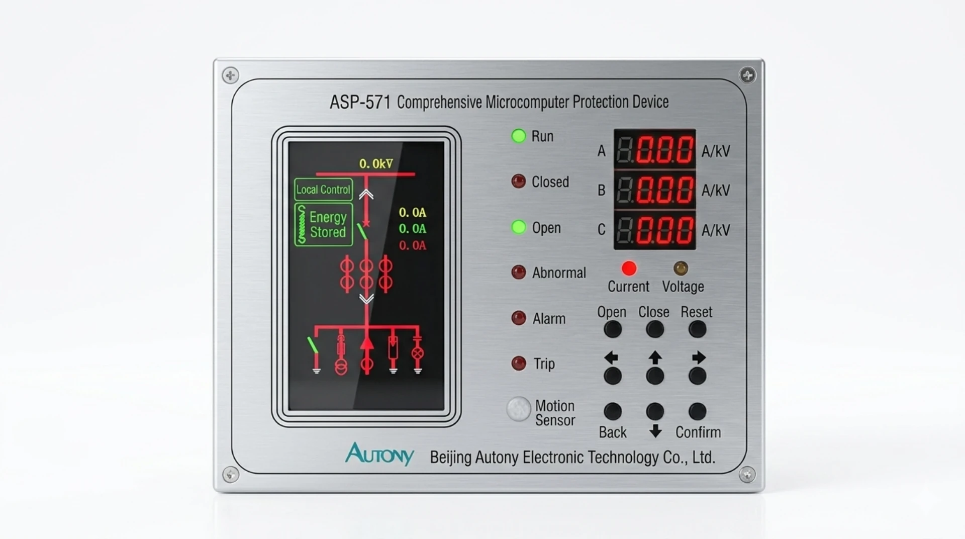
Microprocessor Based Relay: Working Principle, Types and Applications
Microprocessor based relays are digital protection devices that sample CT and VT secondary quantities, convert them into numbers several times per power cycle, and run the protection logic in software rather than in springs, disks and fixed analogue circuits. One hardware platform then carries as many protection functions as its firmware licence allows.
Microprocessor Based Relay at a Glance
Six things change once the logic moves out of hardware into firmware, and they are what the relay is actually bought for:
- Sampling: the relay takes roughly 8 to 80 samples per cycle, so accuracy rests on the anti-alias filter and the A/D converter instead of on coil tolerances.
- Functions: overcurrent (ANSI 50 and 51), earth fault (ANSI 50N and 51N), directional overcurrent (ANSI 67), differential (ANSI 87), distance (ANSI 21) and thermal replica (ANSI 49) can sit in the same case.
- Settings: pickup, time multiplier and curve shape are numbers, so a scheme change costs an upload rather than a panel rebuild.
- Recording: disturbance records and event logs survive the trip, which is what makes a post-mortem possible at all.
- Self-supervision: the watchdog looks at auxiliary supply, memory and A/D path, and blocks any trip it cannot vouch for.
- Communication: IEC 61850-8-1:2011+AMD1:2020 carries GOOSE and MMS to the station bus, alongside Modbus and IEC 60870-5-103.
A relay that has quietly stopped supervising itself is more dangerous than one that never could, because nobody learns that it failed.
On retrofit work the size of the change is easiest to see in panel space: a cubicle built for five electromechanical relays often accepts one digital protection relay doing the same five jobs.
ANSI/IEEE C37.2-2022 assigns the device numbers used above. IEC 60255-1:2022 sets the common requirements for the relay itself, IEC 60255-151:2009 covers overcurrent function performance, and IEC 61000-6-5:2015 is the immunity level usually demanded in substation and plant environments.
The sections below take the working principle stage by stage, then the function list, then how the technology compares with electromechanical and static relays, and finally what to check before specifying one.
What Is a Microprocessor-Based Relay?
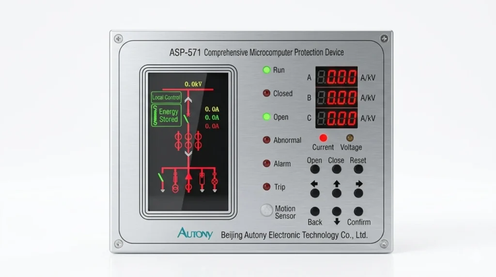
The definition worth writing into a specification is narrower than the marketing one. A microprocessor based relay executes protection algorithms in firmware, so the same hardware can be reconfigured in the field; an electromechanical or static relay keeps whichever characteristic it left the factory with.
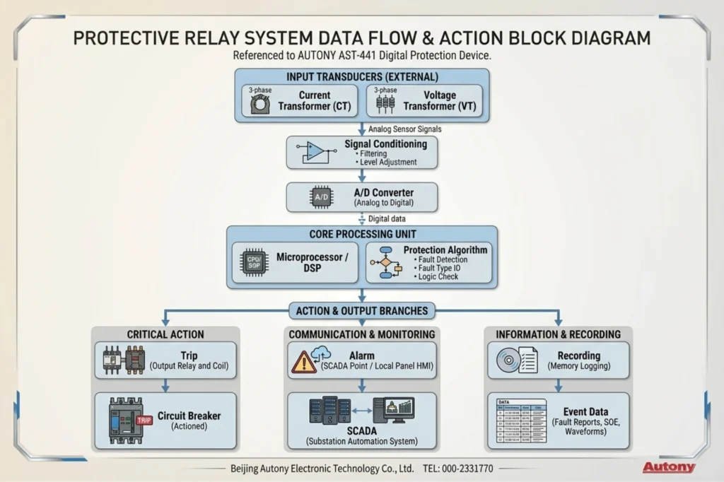
It continuously samples voltage and current signals from CTs and PTs, then converts these analog signals into digital values through an analog-to-digital converter. The microprocessor executes protection algorithms on these digital values to detect faults. When a fault is detected, the relay sends a trip signal to the circuit breaker to isolate the faulty section.
The relay also stores fault records and communicates with SCADA systems for remote monitoring and event analysis. The entire signal flow follows this path:
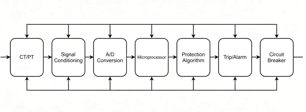
This software-defined architecture gives microprocessor-based relays distinct advantages over older technologies: one hardware platform supports multiple functions, settings can be modified remotely, and protection characteristics can be updated without changing hardware. For engineers upgrading a substation, this means fewer panel changes when protection requirements evolve.
How Does a Microprocessor-Based Relay Work?
Microprocessor relay working principle is a loop rather than a chain: measure, convert, estimate, compare, decide, act, record. The loop repeats every few milliseconds and ends either in a trip contact or in nothing at all. The stages below follow the signal itself.
1. Signal Acquisition
The relay receives analog current and voltage signals from CTs and PTs. These signals represent primary system values, scaled down to levels the relay can handle, typically 1 A or 5 A for CTs, and 100 V or 110 V for PTs.
The input circuits include filtering to remove noise and harmonics that could distort measurements.
2. Analog-to-Digital Conversion
The conditioned analog signals are sampled at a fixed rate and converted into digital values by an analog-to-digital converter.
For 50 Hz or 60 Hz systems, typical sampling rates range from 16 to 24 samples per cycle. Higher rates improve accuracy but require more processing power. The A/D converter’s resolution determines the smallest detectable signal change.
3. Digital Signal Processing
The microprocessor applies digital signal processing to extract useful information from the sampled data.
Common DSP operations include calculating RMS values, removing harmonics, extracting fundamental frequency components, and computing symmetrical components (positive, negative, and zero sequence).
4. Protection Algorithm
The protection algorithm compares processed measurements against programmed settings to detect faults.
| Protection Function | What the Algorithm Checks |
|---|---|
| Overcurrent (50/51) | Current magnitude against pickup threshold |
| Earth fault (50N/51N) | Residual or zero-sequence current |
| Differential (87) | Current difference entering and leaving the zone |
| Distance (21) | Impedance calculated from voltage and current |
| Directional (67) | Power flow direction using voltage reference |
5. Fault Decision
After executing the algorithms, the microprocessor determines whether a fault exists. This decision may combine outputs from multiple protection elements and scheme logic (e.g., inrush blocking or directional supervision).
If a fault is confirmed, the relay initiates the trip sequence. The entire decision process takes milliseconds.
6. Trip Command
The relay sends a trip signal to the circuit breaker through its output contacts. These contacts are rated for the breaker’s trip coil current.
Additional outputs may include alarm signals for annunciation and interlocking signals to prevent unintended operations.
7. Event Recording and Communication
After tripping, the relay records event data for post-fault analysis. Recorded information includes fault current and voltage values, time stamps, operated protection elements, and waveform captures.
The relay communicates with SCADA and other systems through protocols like IEC 61850, Modbus, and DNP3. Communication enables remote monitoring, fault reporting, and setting adjustments.
What Functions Does a Microprocessor Based Relay Provide?
A microprocessor based relay is specified by the functions its firmware carries, and every one of them maps to an ANSI device number. Ten cover most feeders and transformers: ANSI 50 and 51 for phase overcurrent, ANSI 50N and 51N for earth fault, ANSI 67 for direction, ANSI 87 for differential, ANSI 21 for distance, ANSI 27 and 59 for voltage, ANSI 81 for frequency and ANSI 49 for thermal replica. Anything beyond that list needs its own reason on the drawing.
| Protection / Function | ANSI Code | Typical Application |
|---|---|---|
| Instantaneous Overcurrent | 50 | Feeder |
| Time Overcurrent | 51 | Feeder |
| Earth Fault | 50N/51N | Feeder |
| Differential | 87 | Transformer/Generator |
| Distance | 21 | Transmission Line |
| Undervoltage | 27 | Bus/Feeder |
| Overvoltage | 59 | Bus/Generator |
| Frequency | 81 | Generator/Grid |
| Directional Overcurrent | 67 | MV Network |
| Thermal Overload | 49 | Motor/Transformer |
Advantages of Microprocessor-Based Relays
Every advantage below follows from one change: the logic moved out of hardware into firmware in a microprocessor based relay. Each can be demonstrated on a bench before the panel ships, which is why upgrade projects get argued on measured behaviour rather than on claims.
1. Multiple Protection Functions in One Device
A single relay can integrate dozens of protection functions: overcurrent, earth fault, differential, directional, voltage, frequency, and thermal protection, which previously required multiple separate devices. This reduces panel space, wiring, and failure points.
2. Digital Measurement Capabilities
Microprocessor relays provide real-time measurement of current, voltage, frequency, active/reactive power, power factor, energy, and harmonics. Measurements are software-calculated from digitized waveforms, offering higher accuracy than analog methods.
3. Event Recording
The relay logs time-stamped sequences of protection operations, including which elements picked up, which tripped, and the order of events. These records help engineers verify protection scheme performance and understand disturbance sequences.
4. Fault Recording (Oscillography)
Fault recording captures waveform data before, during, and after a fault. Engineers can analyze fault currents, voltage dips, and relay response times using software tools, speeding up post-fault investigation and root cause identification.
5. Self-Diagnostics
The relay continuously monitors its own health through built-in self-test routines. If an internal failure occurs, the relay issues an alarm immediately. This is a major advantage over electromechanical relays, where failures may remain undetected until a fault occurs.
6. Communication Capabilities
Microprocessor relays support protocols like IEC 61850, Modbus, DNP3, and IEC 60870-5-103/104 for integration with SCADA and substation automation systems. This enables remote monitoring, fault notification, setting changes, and data retrieval.
7. Multiple Setting Groups
Engineers can store and switch between multiple setting groups to accommodate seasonal load changes, system configuration changes, or maintenance scenarios. Switching can be done remotely via communication.
8. Remote Monitoring and Control
Operators can view real-time measurements, receive fault notifications, retrieve records, and change settings from a central location. Remote monitoring reduces site visits and enables faster response to system events.
Microprocessor Based Relay vs Electromechanical Relay
This comparison is the one that decides most retrofit jobs. Microprocessor relay working principle replaces torque and spring tension with arithmetic, so a microprocessor based relay holds its accuracy instead of drifting with age, and a scheme change costs an upload rather than a rebuild. Electromechanical units still win on one point: nothing to configure means nothing to misconfigure.
| Feature | Microprocessor Based Relay | Electromechanical Relay |
|---|---|---|
| Operating principle | Digital processing | Electromagnetic/mechanical |
| Protection functions | Multiple | Usually single |
| Setting | Software-based | Mechanical |
| Event recording | Yes | Limited/No |
| Fault recording | Available | No |
| Self-diagnosis | Available | Limited |
| Communication | Yes | Limited/No |
| Remote monitoring | Yes | No |
| Maintenance | Lower | Higher |
| Data measurement | Extensive | Limited |
| Setting groups | Multiple | Usually unavailable |
Microprocessor-Based Relay vs Static Relay
Static relays moved part of the job into electronics already, but the characteristic is still built from resistors, capacitors and comparators, so it cannot be reshaped without replacing parts. Numerical relay types are usually grouped by hardware generation at this point, and the table below is what a specification review actually turns on.
Comparison Table
| Feature | Static Relay | Microprocessor-Based Relay |
|---|---|---|
| Technology | Solid-state circuits (transistors, diodes, ICs) | Microprocessor with firmware and software |
| Protection functions | Single or limited functions per device | Multiple functions integrated in one device |
| Setting method | Potentiometers, resistors, or jumper settings | Digital settings via keypad, software, or remote |
| Measurement accuracy | Moderate | High (digital sampling with DSP) |
| Temperature drift | Susceptible to drift | Minimal (digital compensation) |
| Event recording | None or very limited | Full event logging with time stamps |
| Fault recording | None | Waveform capture for post-fault analysis |
| Self-diagnostics | Limited or none | Continuous built-in self-test |
| Communication | None or basic (RS-232/485 limited) | Multiple protocols (IEC 61850, Modbus, DNP3) |
| Remote monitoring | Not possible | Full remote access and control |
| Setting groups | Single | Multiple, switchable |
| Configuration flexibility | Fixed, cannot add functions without hardware change | Software-defined, functions added via firmware |
| Component ageing | Components drift over time, affecting accuracy | Digital processing eliminates drift |
| Typical applications | Simple fixed protection, legacy panels | Modern substations, automation-ready projects |
Is a Microprocessor-Based Relay the Same as a Numerical Relay?
On a current tender the three names describe almost the same box. Numerical relay types are grouped by platform generation rather than by function count, and the microprocessor based relay sits inside that group: digital is the broad term, while numerical and microprocessor based describe narrower hardware generations.
Understanding the Terminology
The naming reflects different generations of technology development:
| Term | Typical Meaning |
|---|---|
| Digital relay | Relay that uses digital signal processing; a broad term covering most electronic relays |
| Microprocessor-based relay | Relay that uses one or more microprocessors for protection logic and communication |
| Numerical relay | Relay that uses digital signal processing with advanced algorithms (often later-generation relays) |
Microprocessor Relay vs Numerical Relay
Digital relay is the broad category. It includes any relay that converts analog signals to digital form for processing. Microprocessor-based relay and numerical relay are subsets of digital relays.
In practice the split is about when the box was designed, not what it does. Numerical relay types built in the last two decades add faster DSP, Ethernet and IEC 61850, so ask which capability is actually being requested when a specification insists on one name over the other.
Summary
For most engineering and procurement purposes, these terms can be treated as equivalent. When a project specification calls for a “numerical relay” or “microprocessor-based relay,” the requirement amounts to the same thing: a digital protection device with software-based algorithms and communication capability.
What matters is the list behind the name: which protection functions are enabled, which protocols are licensed, and what the guaranteed operating times are. Microprocessor relay applications are bought against that list, not against the label.
Applications of Microprocessor-Based Relays
Microprocessor relay applications reach every voltage level, and the difference between them is mostly which functions get enabled and how many setting groups the plant needs. Each application below has its own default function set.
Substations (MV/HV/EHV)
In a modern substation, a single microprocessor-based relay can perform feeder protection, transformer protection, busbar protection, and backup protection simultaneously. For a 33 kV incoming feeder, the relay combines overcurrent, earth fault, directional protection, breaker control, event recording, and IEC 61850 communication in one device.
This integration reduces panel space, simplifies wiring, and streamlines commissioning. For GIS or AIS switchgear, the relay mounts directly on the panel or in a 19-inch rack.
Distribution Feeders
For a 33 kV or 11 kV distribution feeder, the relay provides phase overcurrent (50/51), earth fault (50N/51N), and directional overcurrent (67/67N) where required. It also includes autoreclose functionality for overhead lines and breaker failure protection.
The relay measures load current, fault current, and power quality parameters. It communicates with SCADA for remote monitoring and control. Fault records help engineers locate and analyze disturbances on the feeder.
Power Transformers
For a 33/11 kV transformer or a large GSU transformer, a microprocessor-based relay provides differential protection (87T), overcurrent backup (51), earth fault protection (51N), and thermal overload protection (49).
The relay includes inrush current blocking and harmonic restraint to prevent misoperation during energization. It also monitors transformer temperature through analog inputs and issues alarms for overtemperature conditions.
Generators
In generator applications, the relay provides differential protection (87G), reverse power protection (32), loss of excitation (40), stator earth fault (59N), over/undervoltage (27/59), and over/underfrequency (81O/81U).
For grid-connected generators, the relay includes synchronising check (25) and directional protection to manage reverse power and islanding conditions. Event records capture startup and shutdown sequences for performance analysis.
Motors
For medium-voltage motors (e.g., 6.6 kV or 11 kV), the relay provides overload protection (49), short-circuit protection (50/51), earth fault protection (51N), negative sequence protection (46), and phase loss protection. It also includes start inhibit and stall protection to prevent damage during starting or overloaded conditions.
The relay monitors motor current, thermal capacity, and starts-per-hour to extend motor life and reduce unplanned downtime.
Transmission Lines
For 66 kV, 110 kV, or higher voltage transmission lines, the relay provides distance protection (21) with multiple zones, directional overcurrent (67), and auto-reclose functions. Modern numerical relays also support line differential protection (87L) using fiber-optic communication channels.
Distance relays use impedance measurement to locate faults accurately. They include communication schemes like permissive overreach and blocking schemes to improve coordination and tripping speed.
Renewable Energy Systems
In solar, wind and battery energy storage systems (BESS), the relay provides ANSI 81 frequency and ANSI 27/59 voltage protection, ANSI 67/67N directional overcurrent, loss of mains protection and anti-islanding detection. Inverter and collector schemes are grouped under renewable energy relay protection.
For inverters and STATCOMs, the relay monitors power quality and interfaces with plant SCADA via IEC 61850 or Modbus.
Industrial Power Systems
Industrial plants, including oil and gas, mining, steel, and chemical facilities, use microprocessor-based relays for backup protection of motors, transformers, generators, and distribution feeders. The relays help coordinate with existing protection systems and support safety compliance.
In plants with emergency generators or UPS systems, the relay handles transfer schemes and monitors power quality. Plant engineers use fault records to troubleshoot electrical faults and improve system design.
How to Select a Microprocessor-Based Relay?
Ten decisions, in this order. Steps four and five are the ones that get skipped, which is how a relay ends up tripping correctly and talking to nothing: microprocessor relay applications decide the function list first, and the hardware follows. The device numbers behind those functions are covered in protective relay functions.
Step 1: Determine System Voltage
Start by confirming the primary system voltage where the relay will be installed.
| Voltage Level | Typical Application |
|---|---|
| Low voltage (≤1 kV) | Industrial distribution, motor control |
| Medium voltage (1 kV – 72.5 kV) | Substation feeders, transformers, motors |
| High voltage (72.5 kV – 245 kV) | Transmission lines, GSU transformers |
| Extra high voltage (>245 kV) | Long-distance transmission, EHV substations |
The relay’s input ratings must match the system voltage. For MV and HV applications, ensure the relay supports the rated voltage and frequency (50/60 Hz).
Step 2: Identify Protected Equipment
Different equipment requires different protection functions. Identify the asset the relay will protect.
| Equipment | Typical Protection Functions |
|---|---|
| Feeder | 50/51, 50N/51N, 67/67N, auto-reclose |
| Transformer | 87T, 50/51, 50N/51N, 49, temperature |
| Motor | 49, 50/51, 46, earth fault, stall protection |
| Generator | 87G, 32, 40, 59N, 27/59, 81O/81U |
| Transmission line | 21, 67, 85, auto-reclose |
| Capacitor bank | 50/51, 59, unbalance protection |
| Busbar | 87B, 50BF, arc flash protection |
Matching the relay to the equipment ensures the right set of protection functions is available.
Step 3: Determine CT/PT Inputs
Verify the CT and PT specifications at the installation point.
CT Parameters to Confirm:
- Ratio (e.g., 400/5 A, 600/1 A)
- Accuracy class (5P10, 10P20, etc.)
- Burden (VA rating)
- Knee-point voltage (for saturation check)
PT Parameters to Confirm:
- Ratio (e.g., 33 kV / 110 V)
- Accuracy class
- Connection type (phase-to-phase or phase-to-ground)
The relay’s analog inputs must match CT secondary ratings (1 A or 5 A) and PT secondary voltages (typically 100 V or 110 V).
Step 4: Define Required Protection Functions
Select the specific ANSI/IEC protection functions required for the application. Refer to the table in Step 2 for guidance.
Also consider:
- Do you need directional protection (67/67N)?
- Is differential protection (87) required?
- Do you need voltage or frequency protection (27, 59, 81)?
- Is breaker failure protection (50BF) specified?
Select only what the system needs. Adding unnecessary functions adds complexity and cost.
Step 5: Check Protection Setting Range
Verify that the relay’s setting range covers the system operating parameters.
| Parameter | Check Against |
|---|---|
| Current pickup range | Minimum and maximum fault current |
| Time delay range | Coordination requirements |
| Curve characteristics | IEC or IEEE inverse curves available |
| Instantaneous setting | Maximum short-circuit current |
The relay must be sensitive enough to detect minimum faults but stable enough to avoid nuisance trips. Check that the minimum fault current is above the relay’s minimum pickup setting.
Step 6: Check Communication Protocols
Determine the communication requirements for the project.
| Protocol | Typical Use |
|---|---|
| IEC 61850 | Modern digital substations |
| Modbus RTU/TCP | Industrial SCADA |
| DNP3 | Utility SCADA |
| IEC 60870-5-103/104 | Utility grid communication |
| Profibus-DP | Industrial automation |
Consider whether the relay needs GPS or IRIG-B time synchronization for event time-stamping.
Step 7: Check Event and Fault Recording
Most projects require event and fault recording for post-fault analysis.
| Feature | Consideration |
|---|---|
| Event records | Number of events stored (e.g., 256, 1024) |
| Fault records | Number of records and waveform duration |
| Record triggering | Manual or automatic on fault |
| Data retrieval | Local download or remote access |
For critical assets, specify relays with detailed fault recording (oscillography) to support root cause analysis.
Step 8: Verify Environmental Requirements
The relay must operate reliably under site conditions.
| Environmental Factor | Check |
|---|---|
| Operating temperature | -25°C to +70°C (typical) |
| Humidity | Condensation risk |
| Ingress protection | IP20 (indoor), IP54 or higher (outdoor) |
| EMC immunity | IEC 61000-6-5 compliance |
| Vibration | Switchgear-mounted applications |
| Altitude | Derating above 1000 m |
Match the relay’s environmental rating to the installation location (indoor control room, outdoor yard or industrial environment).
Step 9: Check IEC/IEEE Compliance
Ensure the relay complies with applicable international standards.
| Source | What it covers | Type | Edition |
|---|---|---|---|
| ANSI/IEEE C37.2 | Device function numbers and acronyms used on single-line drawings | IEEE Standard | 2022 |
| IEC 60255-1 | Common requirements for measuring relays and protection equipment | International Standard | 2022 |
| IEC 60255-151 | Overcurrent function performance, the ANSI 50 and 51 side | International Standard | 2009 |
| IEC 60255-26 | Electromagnetic compatibility requirements for relay hardware | International Standard | 2023 |
| IEC 61850-8-1 | Station bus communication mapped to MMS and GOOSE | International Standard | 2011+AMD1:2020 |
| IEEE C37.112 | Inverse-time characteristic equations used by curve-shape settings | IEEE Standard | 2018 |
| IEC 61000-6-5 | Immunity levels for substation and power plant environments | International Standard | 2015 |
| IEC 60255-27 | Product safety requirements for measuring relays | International Standard | 2023 |
Edition years move, so confirm the current one before quoting a number. Some projects also ask for marine, railway or utility-specific certification. Check project specifications for these requirements.
Step 10: Confirm Testing and Commissioning Requirements
Select a relay that supports easy testing, and settle the test programme before it arrives on site: protection relay testing and commissioning covers the sequence most utilities require.
| Requirement | Check |
|---|---|
| Secondary injection testing | Support for test modes |
| Software tools | PC-based configuration and testing software |
| Commissioning support | Documentation and templates |
| Protection setting file | Export/import capability |
Relays with test mode functionality allow protection engineers to verify settings without tripping breakers. Check that the relay comes with configuration software compatible with your PC environment.
How to Test a Microprocessor-Based Relay
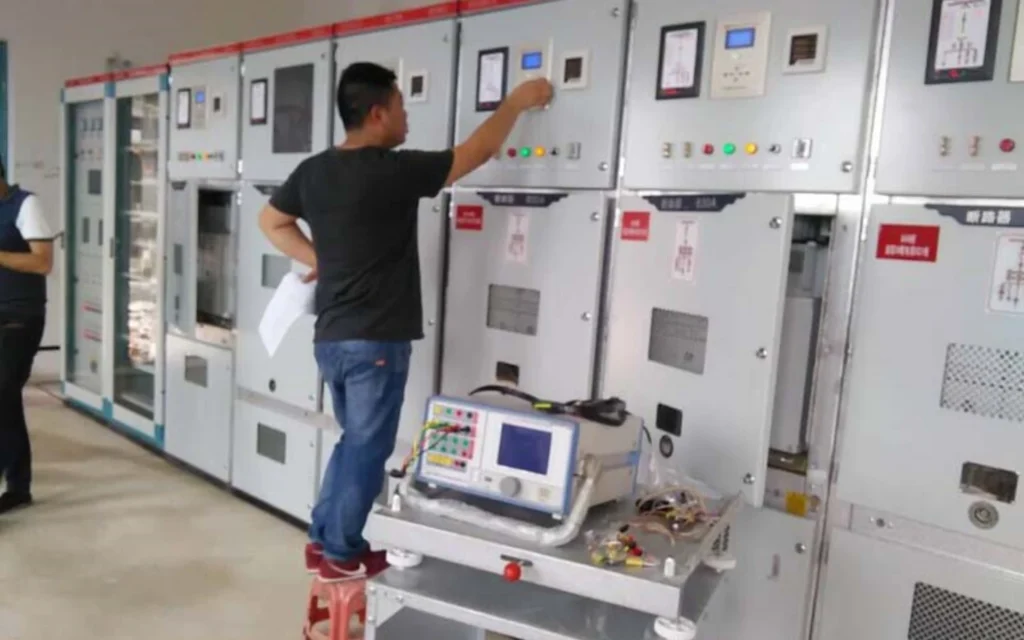
Testing a microprocessor-based relay verifies that it operates correctly within the protection scheme. Commissioning tests confirm proper installation and settings before the relay enters service. Routine periodic tests verify ongoing reliability throughout its service life.
A complete test program covers the following areas:
- Visual inspection – Check for physical damage, loose connections, and proper labeling. Verify that the relay model and firmware version match the project specification.
- Wiring verification – Confirm that CT and PT connections are correct, including polarity for CTs and phase rotation for PTs. Check auxiliary power supply wiring and communication cable terminations.
- CT/PT input test – Inject primary or secondary test signals to verify that CT and PT circuits are connected correctly and that the relay measures the correct values.
- Secondary injection test – Use a test set to inject current and voltage signals directly into the relay inputs. Verify that the relay measures accurately and that protection elements operate at the correct pickup values.
- Protection function test – Test each enabled protection element individually. Verify that time delays, curve characteristics, and instantaneous settings operate within tolerance.
- Trip output test – Verify that trip and alarm outputs activate correctly when protection functions operate. Confirm that output contacts are wired to the correct circuit breaker trip coils and annunciation circuits.
- Communication test – Verify that the relay communicates with SCADA, RTU, or substation automation systems. Check protocol implementation and data exchange for measurements, events, and settings.
- Event recording test – Generate test faults and verify that the relay records events and fault waveforms correctly. Check time-stamping accuracy if GPS or IRIG-B synchronization is used.
- Self-diagnostic test – Verify that the relay’s built-in self-diagnostics function correctly. Force a diagnostic alarm if possible and confirm that the alarm is reported.
- End-to-end test – For line differential or teleprotection schemes, perform end-to-end testing with communication channels active. Verify that both ends operate correctly for internal and external faults.
Commissioning tests cover more ground than routine maintenance tests. For critical applications, some project specifications require factory acceptance testing (FAT) and site acceptance testing (SAT) as part of the commissioning process.
Common Problems With Microprocessor-Based Relays
Microprocessor-based relays are highly reliable, but they are not immune to issues. Most problems stem from installation errors, incorrect settings, or external factors rather than internal failures. The table below lists common problems encountered during commissioning and operation, along with possible causes and recommended checks.
Problem Table
| Problem | Possible Cause | Recommended Check |
|---|---|---|
| Relay does not operate during fault | CT wiring incorrect or open circuit | Verify CT polarity and continuity; check CT secondary circuit resistance |
| Wrong protection settings (pickup too high) | Review setting file against coordination study | |
| Protection element disabled | Check which elements are enabled in the configuration | |
| CT saturation at high fault current | Review CT knee-point voltage and fault current level | |
| Relay trips unexpectedly (nuisance trip) | Pickup setting too low | Verify settings against actual load current |
| Transient inrush or motor starting current | Check inrush blocking settings or add time delay | |
| Incorrect CT ratio entered | Confirm CT ratio matches relay setting | |
| Harmonics or noise on input signals | Check signal filtering and grounding | |
| Relay measures incorrect current or voltage | CT ratio mismatch | Verify CT ratio setting in relay matches physical CT |
| PT ratio mismatch | Verify PT ratio setting matches physical VT | |
| Wiring error (phase reversal, open CT) | Perform primary or secondary injection test | |
| Burden exceeds CT capability | Check CT burden and cable length | |
| Communication failure | Incorrect protocol or settings | Verify baud rate, parity, and protocol match |
| Wiring or termination issues | Check RS-485/Ethernet connections and termination resistors | |
| IP address conflict (Ethernet) | Verify unique IP address on network | |
| IEC 61850 GOOSE configuration error | Check SCD file and published data sets | |
| Event records show incorrect time stamps | No time synchronization | Verify GPS or IRIG-B connection and signal |
| Time zone or DST setting wrong | Check time zone and daylight saving configuration | |
| IRIG-B signal polarity reversed | Verify signal wiring polarity | |
| Relay does not trip breaker | Trip circuit wiring open or shorted | Check trip coil continuity and wiring |
| Auxiliary supply to relay interrupted | Verify relay auxiliary power is present | |
| Output contact not configured correctly | Check output mapping in relay configuration | |
| Breaker anti-pumping circuit activated | Check breaker control circuit | |
| Self-diagnostic alarm triggered | Internal hardware fault | Record fault code and contact manufacturer support |
| Auxiliary power supply out of tolerance | Measure relay supply voltage | |
| Over-temperature condition | Check ambient temperature and cooling | |
| Firmware or configuration issues | Firmware version mismatch | Verify firmware version against project specification |
| Corrupted setting file | Reload settings from backup file | |
| Incompatible configuration for application | Review configuration against protection scheme design |
Troubleshooting Priority
When a problem occurs, follow this priority sequence:
- Check the obvious first – Verify auxiliary power, CT/PT connections, and basic wiring.
- Review event and fault records – The relay captures data that points to the cause.
- Verify settings – Confirm that the settings match the protection study.
- Perform secondary injection – Test individual elements to isolate the issue.
- Check communication – If the relay communicates, check protocol and wiring.
- Contact manufacturer support – For hardware or firmware issues, involve the manufacturer’s technical support team.
Prevention is Better Than Troubleshooting
Most common problems can be prevented by:
- Following the manufacturer’s installation manual
- Performing full commissioning tests before energizing the system
- Using a structured setting management process
- Training maintenance staff on relay operation and testing
- Keeping backups of setting files and configuration
- Regularly reviewing event and fault records for early warning
These practices reduce downtime, lower maintenance costs, and ensure the relay operates reliably when a real fault occurs.
FAQ About Microprocessor-Based Relay
What does a microprocessor based relay do?
A microprocessor based relay measures CT and VT secondary quantities, turns them into numbers, and runs the protection logic in firmware. Unlike electromechanical or static relays with fixed characteristics, it runs software-based protection algorithms. It samples voltage and current signals from CTs and PTs, converts them to digital values, and executes protection logic to detect faults.
How does a microprocessor based relay work step by step?
The relay continuously samples analog signals from CTs and PTs, converts them to digital values through an analog-to-digital converter, and processes the data using digital signal processing techniques. The microprocessor executes protection algorithms that compare measurements against programmed settings. If a fault is detected, the relay sends a trip signal to the circuit breaker. The entire cycle, measure, convert, process, decide and act, happens within milliseconds.
What are the advantages of microprocessor-based relays?
Microprocessor-based relays offer multiple advantages over conventional types:
- Multiple protection functions in one device
- High-accuracy digital measurement (current, voltage, frequency, power)
- Event and fault recording for post-fault analysis
- Built-in self-diagnostics for immediate failure detection
- Multiple communication protocols (IEC 61850, Modbus, DNP3)
- Multiple setting groups for flexible operation
- Remote monitoring and control via SCADA integration
These features reduce panel space, simplify maintenance, and improve system reliability.
What is the difference between a microprocessor relay and a numerical relay?
In modern power system protection, the terms microprocessor-based relay, digital relay, and numerical relay are often used interchangeably. The naming reflects different generations of technology. Digital relay is the broad category that includes any relay using digital signal processing. Microprocessor-based relay and numerical relay are subsets. If there is a distinction, earlier microprocessor relays performed basic sampling and protection, while numerical relays use advanced DSP and communication capabilities. For most engineering and procurement purposes, they can be treated as equivalent.
What is the difference between a microprocessor relay and an electromechanical relay?
Electromechanical relays operate using physical principles: magnetic attraction, induction disks, and spring-loaded contacts. They are single-function devices, settings are adjusted manually with tools, they have no communication capability, and moving parts wear over time. Microprocessor relays replace all moving parts with digital logic. One device handles dozens of functions, settings are entered via software, and communication enables SCADA integration. These features make microprocessor relays the standard for modern installations.
What protection functions can a microprocessor-based relay provide?
A single microprocessor relay can provide dozens of protection functions simultaneously:
| ANSI Code | Function |
|---|---|
| 50/51 | Overcurrent protection |
| 50N/51N | Earth fault protection |
| 67/67N | Directional overcurrent protection |
| 87T | Transformer differential protection |
| 87B | Bus differential protection |
| 87L | Line differential protection |
| 21 | Distance protection |
| 27 | Undervoltage protection |
| 59 | Overvoltage protection |
| 81U/81O | Under/over frequency protection |
| 46 | Negative sequence protection |
| 49 | Thermal overload protection |
| 50BF | Breaker failure protection |
| 25 | Synchronism check |
| 32 | Reverse power protection |
| 40 | Loss of excitation protection |
Are microprocessor-based relays suitable for medium voltage substations?
Yes. Microprocessor-based relays are the standard choice for medium voltage substations (1 kV to 72.5 kV). They provide feeder protection, transformer protection, motor protection, and busbar protection, all within a single device. Their communication capabilities support SCADA integration, and their event and fault recording features help engineers analyze disturbances. For new MV substation projects, microprocessor-based relays are the default selection.
Can a microprocessor-based relay communicate with SCADA?
Yes. Microprocessor-based relays support multiple communication protocols for SCADA and substation automation integration:
- IEC 61850 – Modern digital substation standard
- Modbus RTU/TCP – Industrial SCADA
- DNP3 – Utility SCADA
- IEC 60870-5-103/104 – Utility grid communication
Communication enables remote monitoring, fault notification, setting changes, and data retrieval from a central location.
How is a microprocessor-based relay tested?
Testing a microprocessor-based relay includes several steps:
- Visual inspection and wiring verification
- CT/PT input tests to verify correct connections
- Secondary injection tests to verify measurement accuracy and protection element operation
- Protection function tests for each enabled element
- Trip output tests to confirm correct wiring to breakers
- Communication tests to verify SCADA integration
- Event recording tests to verify fault data capture
- Self-diagnostic tests to confirm internal health monitoring
- End-to-end tests for line differential or teleprotection schemes
Commissioning tests cover more ground than routine periodic maintenance tests. Some projects require factory acceptance testing (FAT) and site acceptance testing (SAT).
What should be considered when selecting a microprocessor-based relay?
Follow these 10 key steps:
- Determine system voltage (LV, MV, HV, EHV)
- Identify protected equipment (feeder, transformer, motor, generator, line)
- Determine CT/PT inputs (ratio, class, burden, saturation)
- Define required protection functions (ANSI codes)
- Check protection setting range (pickup, time delay, curve)
- Check communication protocols (IEC 61850, Modbus, DNP3)
- Check event and fault recording requirements
- Verify environmental requirements (temperature, humidity, IP rating, EMC)
- Check IEC/IEEE compliance (IEC 60255, IEEE C37 series)
- Confirm testing and commissioning requirements
Matching the relay to the application and project specifications ensures reliable protection and avoids costly mistakes.
Conclusion
Microprocessor based relays replaced hardware characteristics with firmware, and every practical difference comes out of that one substitution. Microprocessor relay working principle is the seven-stage loop that runs every few milliseconds; applications differ mainly in which functions get enabled and how many setting groups the plant needs. Specify the function list and the protocols first, then choose the hardware that carries them.
Three checks settle most procurement arguments: the loop time quoted at the relay terminals rather than in the datasheet header, whether self-supervision blocks a trip it cannot verify, and whether the current edition of IEC 60255 appears on the type test report. Everything else is a configuration question that can be answered after delivery.
Related Reading
Where you go next depends on the job in front of you. Writing a specification starts with the device numbers, replacing a panel starts with the application pages, and chasing a trip nobody can explain starts with the records. A microprocessor based relay is only ever as good as the settings it carries and the evidence left behind by the last one.
Digital multifunction protection relay ASL-591H: one hardware platform carrying the functions above.
What are protective relays: the hardware generations this page compares, and where each one is still used.
Working principle of protective relays: the same loop described from the protection side rather than the hardware side.
Numerical transformer differential protection: what ANSI 87T asks of sampling, CT matching and inrush restraint.
Protective relay functions: the ANSI device numbers behind every entry on the function list.
Numerical overcurrent protection relay: ANSI 50/51 settings and curve selection in practice.
Protection relay setting calculation: turning a short-circuit study into the numbers typed into the relay.
Relay testing and commissioning: the sequence used before a panel is energised.



About Author

Hello, I'm Leno Zhang. I have 15 years of experience in the power relay protection industry with extensive pre-sales and after-sales project experience. Our company specializes in various complete sets of relay protection and automation equipment. I can assist customers in solving all practical on-site project challenges and provide optimal integrated solutions.
Tell Us Your Requirement
High Quality
Stable performance, reliable design, ensuring safe operation for power system protection and grid stability.
Fast Delivery
Timely delivery to support your urgent orders and project schedules efficiently and professionally at any time.
Best Warranty
Professional Warranty: Reliable after-sales support for stable relay protection and long-term customer satisfaction.