
-
Leon Zhang Sales Manager
-
Email: sale@relayprotect.com
-
Phone/WhatsApp: +86 13655813266

Vector Groups, Cooling and Ratings on a Power Transformer
A power transformer changes voltage by turns ratio, not by regulation: ratings, vector groups, cooling classes, losses, impedance and how insulation ages.
What does a power transformer nameplate specify and how is it built?
A power transformer steps voltage up or down between network sections with no moving parts, from a few hundred kVA on a plant feeder to several hundred MVA on a transmission tie; IEC 60076-1:2011 fixes what the nameplate promises. The turns ratio sets the voltage ratio, so a 66/11 kV unit carries about six times as many high-voltage turns, and a 20 MVA unit runs at 98.5 to 99.5 percent efficiency. Four assemblies decide service life: a core of 0.23 to 0.30 mm grain-oriented steel losing about 0.9 W per kg at 1.7 T, the windings, the oil and the tap changer, which steps in 1.25 percent increments and is the mechanical part most neglected. The vector group states winding connection, whether the neutral is brought out, and phase shift: Dyn11 reads as a delta high-voltage side, star low-voltage side with neutral, and a 30 degree shift. IEC 60599:2015 guides dissolved gas analysis. Setting review and quotation within 12 hours, MOQ 1, 7-15 working days.
Power transformer is the unit that steps voltage up or down between two parts of a network without moving parts, carrying anywhere from a few hundred kVA on a plant feeder to several hundred MVA on a transmission tie. IEC 60076-1:2011 fixes what the nameplate promises.
At a glance
- IEC 60076-1:2011 defines rating as apparent power at the terminals, not what the downstream cable can carry.
- A 20 MVA unit at 6 percent impedance passes roughly 16.7 times rated current into a terminal fault.
- No-load loss runs for 8,760 hours a year. Load loss only accrues while the unit carries current.
- Dyn11 means the LV phasor sits at clock hour 11 when the HV reference is held at 12.
- Two units can run in parallel only at the same vector group, ratio and close impedance values.
- ONAF fan cooling typically adds about 40 percent to the ONAN rating on the same frame.
- Every 6 K above 98 degrees Celsius halves the life of cellulose winding insulation.
- The unit itself carries almost no protection. Differential, Buchholz and winding temperature are separate devices.
What a power transformer actually does
The ratio between the two sides is the turns ratio, so a 66/11 kV unit carries about six times as many turns on the high-voltage winding as on the low-voltage one. Nothing rotates, nothing opens, and at 20 MVA the efficiency sits between 98.5 and 99.5 percent. Stepping down from 132 kV to 11 kV on a grid injection point, the same physics applies at every size.
Every power transformer has at least two windings per phase, and the two never touch electrically.
What the device cannot do is regulate.
Secondary voltage falls as the load rises, in proportion to the impedance voltage, and drops again when the power factor falls. The only automatic correction inside most units is a tap changer stepping in 1.25 percent increments, which is why a network with a wide daily swing needs either an on-load tap changer or a separate voltage regulator. Specifying a fixed-tap unit on a feeder that runs from 2 MVA at night to 18 MVA at midday produces chronic low voltage on the far end, and no amount of relay setting work will fix it.
Core, windings and the parts that fail first
Selecting a relay for a live project?
Send the system voltage, CT ratio and tripping scheme. Our engineers confirm the model and reply within 12 hours.
Four assemblies decide the service life of an oil-immersed unit, and two of them are mechanical rather than electrical. Knowing which one your maintenance contract actually covers is worth more than another page of catalogue figures.
The core is a stack of grain-oriented silicon steel, laminated at 0.23 to 0.30 mm and cut with mitred joints so the flux runs along the grain. At 1.7 T a modern grade loses about 0.9 W per kg, which is why no-load loss barely moves between two manufacturers quoting the same flux density.
| Assembly | Typical failure | What you see before it fails | Reference |
|---|---|---|---|
| On-load tap changer | Selector or diverter contact wear, coking of the oil in the compartment | Rising acetylene in dissolved gas analysis, tap change time drifting | IEC 60214-1:2014 |
| Bushings | Capacitance and tan delta drift in the graded core | Tan delta above 0.7 percent, partial discharge at terminations | IEC 60137:2017 |
| Winding insulation | Thermal ageing of cellulose, loss of tensile strength | Furan content in the oil, rising winding temperature | IEC 60076-7:2018 |
| Gaskets and valves | Oil weeping, moisture ingress through breathers | Water content above 20 ppm at 60 degrees Celsius | IEC 60076-2:2011 |
Table 1. Four assemblies, ranked by how often they appear in our own service records, with the measurement that catches each one early.
The order matters more than the list.
A tap changer has moving contacts inside a compartment that most boards never open, and a diverter with 300,000 operations behind it will coke its own oil. Winding insulation, given adequate cooling and dry oil, usually outlives the plant around it. Buying the lower no-load loss figure while ignoring tap changer access is the commonest false economy in this table.
Vector groups and why Dyn11 is the distribution default
The vector group is a compact statement of three things at once: how each winding is connected, whether the neutral is brought out, and the phase shift between the two sides. Dyn11 reads as a delta-connected high-voltage side, a star-connected low-voltage side with a neutral, and a phase shift corresponding to clock hour 11.
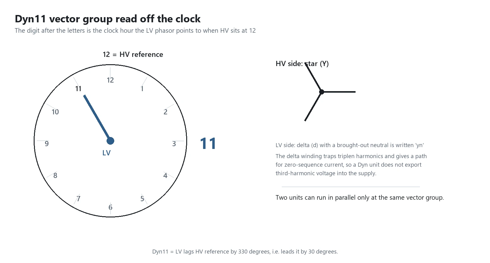
Dyn11 dominates distribution for three reasons that have nothing to do with convention.
The delta winding on the high-voltage side gives zero-sequence and third-harmonic currents somewhere to circulate, so the magnetising current stays close to sinusoidal and the upstream network does not see the harmonic voltage. The star point on the low-voltage side gives single-phase loads a neutral, which is what a lighting and socket board actually needs. And the 30 degree shift works cleanly with the generator and feeder arrangements most boards are drawn for.
Paralleling is where the group stops being academic. Two units with different group numbers have tens of volts between corresponding phases and cannot be tied together, full stop. Two units of the same group but impedance values more than about 10 percent apart share load in inverse proportion to impedance, so the lower impedance unit reaches its rating first and trips, taking its share of the load with it.
Cooling classes decoded: ONAN, ONAF and OFAF
Four letters describe the whole cooling arrangement. The first pair describes what touches the windings, the second pair what carries the heat away from the tank. Reading them in that order removes most of the mystery from a quotation.
| Class | Internal circuit | External circuit | Rating step on the same frame |
|---|---|---|---|
| ONAN | Oil, natural convection | Air, natural convection | Base rating |
| ONAF | Oil, natural convection | Air, fans forced | Up to about 140 percent of ONAN |
| OFAF | Oil, pumps forced | Air, fans forced | Up to about 170 percent of ONAN |
| ODAF | Oil, directed through the windings | Air, fans forced | Largest frames, above roughly 100 MVA |
| AN / AF | Air only, dry type | Air, natural or fans | Indoor installations, IEC 60076-11:2016 |
Table 2. Reading the four-letter cooling code left to right, with the rating step each stage buys.
Each stage costs you a dependency.
An ONAF rating assumes the fans start. Lose the auxiliary supply in a substation during a heat wave and the unit is back at its ONAN number, which may be below what the load needs. Wire the fan loss into an alarm rather than a trip, because the operator needs the option of shedding load before the winding temperature relay does it for them.
Ratings on a power transformer nameplate that decide the spec
Six lines on a nameplate carry nearly all the risk, and procurement habitually reads two of them. The table below is what we check when a client sends a single-line for review, in the order the numbers interact.
| Line | What it fixes | Typical value | Consequence of reading it loosely |
|---|---|---|---|
| Rated power, MVA | Apparent power at the terminals under the stated cooling | 5 to 250 MVA | A 20 MVA ONAF figure quoted as the ONAN base |
| Rated voltages | No-load ratio and the taps available around it | 66 kV plus or minus 8 steps of 1.25 percent | Taps cannot reach the network voltage extremes |
| Vector group | Phase shift and the availability of a neutral | Dyn11 | Second unit cannot be paralleled with the first |
| Impedance voltage | Fault level and voltage regulation together | 6 to 12 percent at rated taps | Switchgear specified below the actual fault contribution |
| Insulation levels | Lightning impulse and power frequency withstand | 325 kV BIL for 66 kV, 170 kV BIL for 33 kV | Winding fails its own routine test |
| Temperature rise | Headroom before insulation ageing accelerates | Top oil 60 K, winding 65 K | Insulation life halved by a hot enclosure |
Table 3. Six nameplate lines, the sequence they interact in, and what gets expensive when one is read in isolation.
Taps cannot be changed under load unless the unit has an on-load changer. An off-circuit tap switch must be operated de-energised and interlocked with the isolator, which is why “plus or minus 5 percent by off-circuit links” on a quotation predicts a shutdown every time the network voltage moves.
The nameplate of a power transformer is a set of coupled numbers, not a menu.
Raising the impedance from 6 to 10 percent cuts the fault contribution by nearly 40 percent and lets the downstream switchgear stay at 25 kA, but it also doubles the voltage drop at full load on a poor power factor. A plant with large motor starting does not want the higher number. Ask for the impedance together with the tolerance, which IEC 60076-1:2011 sets at plus or minus 10 percent of the declared value, because a nameplate 6 percent can arrive as 5.4 percent and raise the fault level you sized the board around.
Losses, efficiency and what each kilowatt really costs
Losses split into two kinds with completely different economics. No-load loss comes from magnetising the core and is present whenever the unit is energised, day and night, loaded or not. Load loss comes from resistance and stray flux and only appears when current flows.

The arithmetic behind a tender evaluation is short.
Take a 20 MVA unit with 18 kW of no-load loss and 105 kW of load loss at rated current. The no-load component costs 18 kW times 8,760 hours, about 158,000 kWh a year, whatever the load does. Over a 25 year life at 0.09 dollars per kWh that is roughly 355,000 dollars before anyone has drawn a single ampere. A competitor offering 14 kW of no-load loss for 40,000 dollars less than another is not automatically the better bid once the capitalised loss figure is written into the comparison.
Load loss is evaluated against the load factor, not against the rating. A standby unit that carries 10 percent load for most of its life rarely justifies paying for low load loss, while a base-loaded industrial injection point usually does.
Impedance voltage and the fault level it sets
Impedance voltage is the primary voltage, as a percentage of rated value, that drives rated current in a short-circuited secondary measured at the winding temperature reached during the test. Nobody remembers the definition. Everybody uses the number.
The relationship to fault current is direct. A three-phase fault at the terminals passes rated current divided by the per-unit impedance, so a unit at 6 percent passes about 16.7 times rated current, and one at 10 percent passes about 10 times. For a 20 MVA unit at 11 kV, rated current is 1,050 A, which puts the terminal fault contribution at roughly 17.5 kA for the low impedance design and 10.5 kA for the higher one.
That single line decides the switchgear rating, the cable cross-section and the grading study, and it is specified before anybody has run a load flow.
Oil, paper and how insulation actually ages
Cellulose degrades by a chain-scission reaction driven by heat, oxygen and water. Remove all three and laboratory paper lasts centuries. In a sealed tank with an ageing breath and a 60 degree Celsius top oil, you get decades.

The loading rule everyone uses comes from the ageing work behind IEEE C57.91-2011. Paper held at 98 degrees Celsius has a nominal life. Raise it 6 K and the remaining life halves. Run at 104 degrees for a decade and you have spent twenty years of insulation in ten, which is exactly what happens to units in enclosures with poor ventilation in a hot climate.
Water is the partner of heat in that reaction. Tensile strength of insulation paper falls steeply once moisture by dry weight passes about 2 percent, and 4 percent is taken as the end of life. Silica gel breathers and oil sampling every twelve months cost very little against that curve, and dissolved gas analysis interpreted under IEC 60599:2015 picks up incipient faults before any other test.
Where the power transformer stops and protection starts
A power transformer carries almost no protection of its own. What it has is a set of mechanical devices that report condition, and a set of external relays that decide when to open the circuit breakers feeding it. Keeping those two categories separate in the specification avoids most review errors.
ANSI/IEEE C37.2-2022 assigns the electrical functions their numbers. 87T is the transformer differential element, 51 is the time-delayed overcurrent backup, 50 is the instantaneous element, and 50N or 51N handle earth fault on the star side. Restricted earth fault, usually written 87N, covers the turns nearest the star point where a standard differential element is blind. The complete schemes and single-lines for those functions sit in our guide to transformer protection schemes, and the device level split between relays and mechanical trips is set out under types of transformer protection.
None of those functions live inside the tank. Each one runs in a separate device, and the only physical link between them and the interruption is a pair of wires into the trip coil of the upstream breaker. A unit with perfect insulation and no functioning trip path still clears nothing when it fails.
Three things make transformer protection harder than feeder protection.
Magnetising inrush. Energising a unit at a voltage zero crossing drives the core into saturation and draws 8 to 12 times rated current that decays over 0.1 to 1 second. Differential relays restrain on second harmonic content, typically above 15 to 20 percent, and that setting has to survive an energisation during a no-load test.
Tap position and CT ratio mismatch. A differential relay compares currents through two CT sets whose ratios were chosen for one tap position. Moving the tap changer introduces a mismatch of a few percent, and the relay slope has to tolerate it without losing sensitivity. The working principle, including bias characteristics, is described in our differential relay note.
Our integrated transformer protection devices pair the 87T element with the auxiliary inputs a unit actually needs, for two-winding and three-winding applications.
Selection checklist: sizing to the duty, not to the catalogue
Six questions settle the specification before the first quotation arrives. Work down the table, because later answers can invalidate earlier ones.
| Question | If yes | If no | Number to check |
|---|---|---|---|
| Does the load swing more than 3 to 1 across the day? | On-load tap changer plus a voltage profile study | Off-circuit taps are enough | Ratio and number of steps |
| Does the network need a neutral on the secondary? | Star secondary, written yn in the vector group | Delta secondary is acceptable | Vector group letter inside |
| Is the prospective fault below the switchgear rating? | Standard impedance is sufficient | Raise impedance or re-rate the board | Impedance plus its tolerance |
| Will the unit run at over 80 percent load most of the year? | Capitalise load loss in the evaluation | No-load loss carries more weight | Both loss kW figures |
| Is the enclosure sealed, hot or poorly ventilated? | Derate or force the cooling | ONAN base rating stands | Ambient inside the room |
| Will it ever be paralleled with an existing unit? | Match group, ratio and impedance | Circulating current is not a concern | Existing unit nameplate |
Table 4. Six questions in the order that avoids rework, with the figure that settles each answer.
When a power transformer is the wrong answer
Four requests arrive in review meetings every year that no transformer can satisfy, and each one has a different correct answer.
- Voltage regulation on a feeder with a wide swing. Transformation is fixed by the turns ratio. Ordering more MVA will not hold secondary voltage up, and the correct answer is an on-load tap changer or a dedicated voltage regulator.
- Reactive power support. A transformer absorbs and passes reactive power but does not generate it. Power factor correction on a board that runs at 0.8 belongs in a capacitor bank sized separately.
- Galvanic isolation for electronics or control circuits. Using an 11 kV class unit to isolate a 24 V control supply is expensive and gives nothing the Wien bridge did not. Use a control transformer or an isolating module rated for the circuit.
- DC applications. Induction needs a changing flux. There is no direct current transformer, and a DC link uses converters on both ends with no magnetic coupling between them.
Conclusion
Power transformer specification comes down to five coupled numbers: MVA, voltage ratio, vector group, impedance and the two loss figures. Read them as a set and against the duty the unit will actually see, and the majority of commissioning surprises disappear. Everything else on the drawing is detail that follows.
Then confirm what protects it. A well specified unit with no differential element, no Buchholz relay and no winding temperature alarm has three ways to fail that nobody will know about until the dissolved gas results come back.
Frequently asked questions
What is the difference between a power transformer and a distribution transformer?
In IEC usage the two overlap and the boundary is drawn by application rather than by a hard rating. Units feeding transmission networks and running near full load with high capitalised losses sit in the power class. Units feeding final distribution circuits, optimised for low no-load loss because they are energised all day at light load, are usually called distribution transformers. The construction and the standards are largely the same family.
What does Dyn11 actually mean?
The capital D is a delta-connected high-voltage winding, y is a star-connected low-voltage winding, n means the neutral on the low-voltage side is brought out, and 11 is the clock position of the low-voltage phasor when the high-voltage reference phasor is held at 12. Each hour is 30 degrees, so 11 describes a 30 degree lead of the low voltage.
How do I size a transformer for a plant?
Add the connected load, apply a diversity factor for what runs together, then divide by the target power factor to convert kW to kVA. Size the unit above that figure with headroom for the largest motor starting, which usually binds rather than the running total, and then check the impedance against the prospective fault level at the board.
Why does impedance voltage matter so much?
It sets two opposing quantities at once. A low impedance gives good voltage regulation but contributes a high fault current, so the downstream switchgear has to be rated further up. A high impedance limits fault current but makes the secondary voltage sag under load and during motor starting. The value chosen is a compromise between those two, decided by what is downstream.
How long does a transformer last?
Thirty to forty years is normal for an oil-immersed unit run within its temperature limits, and forty-plus years is common when oil stays dry and the load stays moderate. Insulation ageing is the binding constraint, and it roughly doubles for every 6 K of operation above 98 degrees Celsius. Continuous overloading to 130 percent can cut that life to single digits in years.
Can two transformers be run in parallel?
Yes, provided the vector group is identical, the ratios match within a fraction of a percent, and the impedance figures are within about 10 percent of each other, so the load divides proportionately. Otherwise a circulating current flows between the two secondaries even at no external load, which heats both units and wastes rating.
What should be tested before energising?
Insulation resistance and polarisation index, winding resistance, turns ratio on every tap position, vector group verification, oil dielectric strength and moisture content, plus functional checks of the Buchholz relay, pressure relief device and winding temperature indicators. Then verify the protection settings, including 87T slope and second harmonic restraint.
Related reading
- Transformer protection schemes, for the single-lines from 11 kV up to 220 kV.
- Types of transformer protection, the split between electrical relays and mechanical devices.
- Setting 50/51 overcurrent elements, including the grading margin calculation.
- Substation, where this equipment sits in the wider arrangement.
Field record
Vector groups and cooling classes are the two fields that most often come back wrong on a client datasheet, and our record shows the range they have to cover: 6 kV distribution transformers in Kazakhstan, 11 kV in Nepal and the UAE, 33 kV in Ghana and Iraq, 66 kV in Qatar, 110 kV in Myanmar and Saudi Arabia, and 154 kV on the South Korean project. Plants and voltages by country: project record.
Sources and standards
| Source | What it covers | Type | Edition |
|---|---|---|---|
| IEC 60076-1:2011 | General requirements: rating, taps, tolerances, tests | Standard | 2011 |
| IEC 60076-2:2011 | Temperature rise limits for oil-immersed units | Standard | 2011 |
| IEC 60076-3:2013 | Insulation levels, dielectric tests and external clearances | Standard | 2013 |
| IEC 60076-5:2006 | Ability to withstand the effects of short circuit | Standard | 2006 |
| IEC 60076-7:2018 | Loading guide and thermal ageing of cellulose insulation | Standard | 2018 |
| IEC 60076-10:2016 | Determination of sound levels | Standard | 2016 |
| IEC 60076-11:2016 | Dry-type transformers, AN and AF cooling | Standard | 2016 |
| IEC 60214-1:2014 | On-load tap changers, performance and type tests | Standard | 2014 |
| IEC 60599:2015 | Interpretation of dissolved gas analysis in mineral oil | Standard | 2015 |
| IEEE C57.91-2011 | Loading guide and insulation life loss for mineral-oil units | Standard | 2011 |
| ANSI/IEEE C37.2-2022 | Device function numbers including 87T, 50, 51 and 87N | Standard | 2022 |
Table 5. Every standard cited above, with the edition each figure in this guide was taken from.
Losses and ageing figures quoted here come from manufacturer catalogues and our own commissioning records on units between 5 MVA and 63 MVA, 2021 to 2026. They describe what we saw on those installations and nothing beyond them.
Related guides: Power distribution · Contactors · Annunciator
Questions on the settings in this guide go to the engineering team, normally answered the same working day.
Related product: Three-Winding Transformer Differential Protection Relay
About Author

Hello, I'm Leon Zhang. I have 15 years of experience in the power relay protection industry with extensive pre-sales and after-sales project experience. Our company specializes in various complete sets of relay protection and automation equipment. I can assist customers in solving all practical on-site project challenges and provide optimal integrated solutions.
Tell Us Your Requirement



High Quality
Stable performance, reliable design, ensuring safe operation for power system protection and grid stability.
Fast Delivery
Timely delivery to support your urgent orders and project schedules efficiently and professionally at any time.
Best Warranty
Professional Warranty: Reliable after-sales support for stable relay protection and long-term customer satisfaction.