

-
Leon Zhang sales consultant
-
Email: zxl635973785@gmail.com
-
Phone/WhatsApp: +86 13655813266
87M Relay: How It Works and When Is It Required?
87M Relay: How It Works and When Is It Required? |
An 87M relay is the ANSI function number for motor differential protection: it compares the current entering and leaving a motor stator winding and trips when the two no longer match. That comparison catches internal winding faults which overcurrent protection cannot resolve. This page covers how it works, what it does not cover, and when the scheme is worth specifying.
Written by Leon Zhang, Protection Application Engineer · Technical review by Li Ming, Electrical Engineer · Last reviewed September 2026
What Is an 87M Relay?
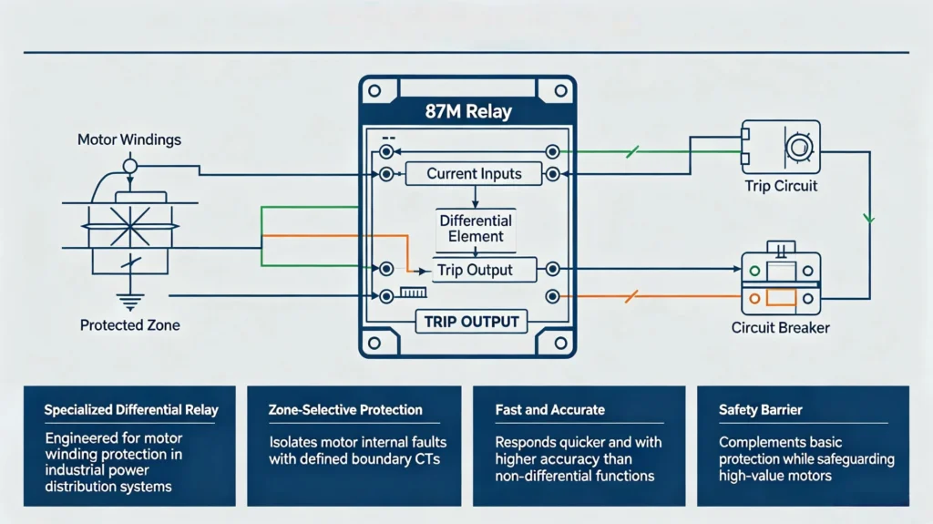
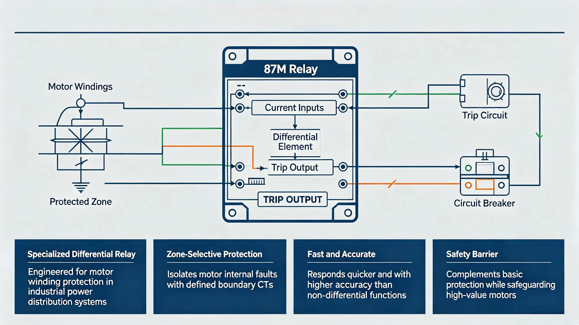
An 87M element is a differential relay built specifically for motor windings.
It protects only inside the zone bounded by its two CT sets, which makes it faster and more sensitive than any motor protection function that measures current at one point. It does not replace overload, thermal or earth-fault protection. It sits alongside them.
What Does ANSI 87M Mean?
In the IEEE C37.2 device numbering system, 87 means differential protection and the suffix “M” narrows it to motors.
ANSI 87M is therefore the function number for motor differential protection, separate from the same 87 family applied to other plant.
The 87 family splits by protected object, and the suffixes are not interchangeable:
| ANSI Function | Protected Equipment | Main Protection Principle |
|---|---|---|
| 87M | Motor | Differential protection for motor stator winding internal faults |
| 87T | Transformer | Differential protection for transformer winding and bushing faults |
| 87B | Busbar | Differential protection for substation busbar internal faults |
| 87L | Transmission Line | Pilot differential protection for overhead line and cable faults |
The difference matters at starting.
A motor draws five to seven times rated current while accelerating, and that inrush passes through both CT sets in the same direction. It cancels in the differential calculation, so an 87M element needs no inrush blocking. An 87T element on a transformer does.
87M Relay Working Principle: Current Comparison
The principle is a current balance across a fixed zone.
Two CT sets, one at each end of the stator winding, feed the same relay.
Anything that changes the balance between them is either a fault inside the zone or a measurement error the relay has to be told how to ignore.
Current Comparison Principle
Two sets of current transformers (CTs) sit at the line-side and neutral-side terminals of the stator winding. The relay samples both sets continuously and brings them to a common base. The operating quantity is:
Id = | I1 − I2 |
I1 is the current entering the zone, I2 the current leaving it, both referred to the same base.
Most relays also form a restraint quantity, usually Ir = (I1 + I2) / 2. Some use the larger of the two instead.
Under normal running and external faults the difference stays near zero once ratio and polarity are matched.
An internal stator fault breaks that balance, and the differential current climbs. When it crosses the biased characteristic, the element trips the motor breaker.
Four things stop that from becoming a nuisance trip. CT ratio matching, polarity verification, saturation immunity, and a bias slope wide enough to cover the measurement error.
Internal Fault vs External Fault
An 87M element answers one question. Was the fault between the two CT sets? Everything outside stays restrained. The table below is the acceptance view for commissioning.
| Condition | Differential Current | 87M Response |
|---|---|---|
| Normal motor operation | Low (near zero) | No trip |
| External system fault | Ideally low (restrained) | No trip |
| Internal stator phase-to-phase fault | High | Instant trip |
| Internal stator ground fault | Set by the grounding method | Covered on low-resistance grounded systems; add 50N/51N where the system is ungrounded or high-resistance grounded |
Boundary: 87M protection stops at the CT sets.
Faults on the supply side of the line CT, or downstream of the neutral CT, are outside the zone and are cleared by other protection.
What Does 87M Differential Protection Protect Against?
Overcurrent protection answers “how much current is flowing”. 87M motor differential protection answers “is the current still balanced”. The three fault types below are the ones where that second question earns its cost.
Phase-to-Phase Faults
A short between two phases in the stator is the fault an 87M element was built for.
Fault current is high and the damage builds in milliseconds, so tripping time is what decides whether the motor is repairable. Overcurrent elements see it, but only once it has grown large enough to stand out from starting current.
Stator Internal Faults
Conventional overcurrent protection is poor at turn-to-turn faults, where the fault current is a fraction of rated and the motor keeps running normally. 87M protection sees the imbalance directly. That is the fault it buys you time on.
Ground Faults Within the Protection Zone
In-zone ground faults are the weakest case for 87M protection, and what decides it is the grounding method.
With low-resistance grounding the fault current is large enough for the differential element alone to catch most in-zone earth faults. On an ungrounded or high-resistance grounded system the earth-fault current is held deliberately low, which puts it below what the differential element can separate from CT error, so a dedicated 50N/51N element is still needed.
What 87M Does Not Normally Replace
87M protection is one element in a scheme, not the whole scheme. These five functions stay in the design:
- Overload protection and thermal protection (49)
- Locked-rotor and motor stall protection (50LR/51LR)
- Phase loss and negative sequence protection (46)
- Independent earth-fault protection (50N/51N)
- Under/over-voltage protection (27/59)
87M Motor Differential Scheme: Arrangement and Zone
Three things decide whether the scheme works: where the CTs sit, how the zone is drawn, and how the bias characteristic is set.
Typical 87M Protection Arrangement
A complete scheme is a single closed loop. The five elements below are the loop, in order.
- Motor stator winding, the protected object
- Two CT sets, one at the line side and one at the neutral side
- 87M relay, fed from both sets
- Trip circuit, carrying the trip command to the breaker
- Motor circuit breaker, which removes the motor from the bus
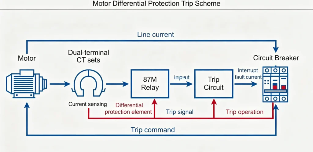
Everything between the two CT sets is treated as internal, which means the motor terminal box, the winding, and the cable up to the neutral CT all sit inside the zone and any fault in that span trips the breaker.
How the Differential Protection Zone Is Defined
The zone is drawn by the CT positions, not by the relay settings.
Everything between the line-side CT and the neutral-side CT is inside; anything beyond them is external and belongs to overcurrent, busbar or line protection.
The payoff is selectivity.
An external fault produces restraint, not a trip, so a downstream short circuit does not take a healthy motor off the bus. The one thing to watch is a CT that saturates during that external fault, which is what the bias setting is for.
Percentage Differential / Biased Differential Protection
The bias characteristic is what sets where the element stops trusting its own measurement.
Two CTs of the same class still differ by a few percent under normal load, and a CT going into saturation during an external fault can differ by many times that. The relay divides the operating quantity by the through-current and only trips above a threshold that rises with it. A low-current internal fault sits in the sensitive part of the curve. A heavy through-fault sits in the stable part.
The same characteristic covers starting inrush and a downstream short circuit without retuning between them.
When 87M Is Required: Rating, Voltage and Criticality
No standard sets a fixed kW threshold above which 87M is required.
Practice turns on four things: what the motor costs, what its downtime costs, what voltage it runs at, and how fast an internal fault has to be cleared.
Large and High-Value Motors
A motor that costs more to replace than to protect gets 87M.
Winding rewinds are expensive, lead times for a replacement frame are long, and a failed motor often damages the driven equipment as well.
Critical Motors in Industrial Plants
Where a stopped motor stops the plant, 87M is usually specified regardless of its rating: pumps on a once-through process, compressors, large fans, mills, and heavy-duty conveyors. The justification is the cost of an unplanned outage, not the cost of the motor.
Medium- and High-Voltage Motors
Medium-voltage and high-voltage motors are where 87M is most often standard.
They already have CT sets for metering and protection, which is the main practical precondition for a differential scheme. On low-voltage motors those CTs usually do not exist, which is why 87M is rare below 1 kV.
Motors Where Fast Internal Fault Clearing Is Important
Where internal fault clearing time is the deciding factor, 87M is the only element fast enough.
Trip time is set by the relay’s own operate time, typically one to two power cycles, not by how long the fault takes to grow. If the motor is one you would rather repair than replace, see which motors need differential protection for the rating and criticality thresholds.
87M vs Other Motor Protection Functions
Each function in the list covers a different failure mode, and none of them substitutes for another. The motor protection relays range shows how these functions are grouped into hardware.
| Protection Function | Main Purpose | Typical Fault/Condition |
|---|---|---|
| 87M | Differential zone selective protection | Internal stator winding faults |
| 50/51 | Overcurrent and short-circuit protection | General short circuit and overload current surge |
| 49 | Thermal overload protection | Motor overheating and long-term overload |
| 46 | Negative sequence protection | Three-phase current unbalance and phase loss |
| 50LR/51LR | Locked-rotor protection | Motor starting stall and rotor locking |
| 50N/51N | Residual ground fault protection | Motor system ground faults |
87M vs Overcurrent Protection
The distinction that matters: 50/51 answers “is there too much current anywhere in this circuit”, and 87M answers “is the current unbalanced inside this motor”. A 50/51 element cannot separate a fault in the motor from a fault on the feeder. An 87M element does not care about the feeder. The two are compared in more detail under motor differential protection vs overcurrent protection.
ANSI 87M Settings and Application Considerations
Four settings decide whether the element is stable or a nuisance. The first two are wiring, not settings. The last two are where most commissioning time goes.
CT Ratio and Matching
Both CT sets must share a ratio, an accuracy class and a saturation characteristic.
Any mismatch shows up as standing differential current at full load, which is exactly the quantity the element is watching. Our notes on motor differential protection CT wiring cover the connection side of this.
CT Polarity
One CT wired the wrong way round doubles the apparent differential current instead of cancelling it, so the element trips as soon as the motor is energised. Polarity is the first thing to prove during commissioning, before any setting is touched.
Differential Pickup Setting
Pickup trades sensitivity against nuisance tripping.
Set it too low and the standing error between two real CTs trips the motor on load. Set it too high and a turn-to-turn fault stays invisible. The starting point is the measured imbalance at full load, plus margin.
CT Saturation and Stability
An external short circuit drives both CTs hard, and the two rarely saturate in step.
The mismatch appears as differential current while nothing is wrong inside the motor.
The bias characteristic and any saturation detector in the relay are there to hold the element back for exactly this case.
Application Example: Critical Compressor Motor
87M Protection for a Medium-Voltage Motor
Application scenario: a 6 kV critical compressor motor in a chemical plant, running continuously, with matched dual-terminal CT sets and an ANSI 87M differential relay.
Fault response: an internal phase-to-phase short breaks the balance between the two CT sets and the differential current exceeds pickup.
The element classifies the fault as in-zone, trips the motor breaker, and the compressor comes off the bus in under two power cycles. The motor goes to a rewind. Without the differential element it would have gone to a replacement.
How to Choose an 87M Relay?
Selection starts from the project parameters, not from a parameter table. These five checks cover what decides the order.
Check the Motor Rating and Voltage
Start from the motor rated voltage and rated power.
A large MV or HV motor needs a relay whose CT inputs stay accurate at the starting current, which is where a marginal input rating shows up first.
Check CT Configuration
Confirm that the CT ratio, accuracy class and wiring arrangement suit the relay input, and that the two CT sets are a matched pair rather than two samples from different batches.
Check Required Protection Functions
An 87M element on its own leaves the motor unprotected against overload and unbalance.
Specify an integrated device that also carries 50/51 overcurrent, 49 thermal, 46 negative sequence and 50N/51N earth fault.
Check Communication and Integration Requirements
If the plant runs a SCADA or substation automation system, check the protocol before ordering.
IEC 61850 and Modbus are the two the industry asks for most, and fault records matter as much as the trip itself.
Check Testing and Commissioning Requirements
The relay should be testable on site without external test equipment: polarity, secondary injection, the differential characteristic, and the trip circuit.
If you are specifying now, the 87M relay datasheet lists the tests supported together with the pickup and bias setting ranges.
87M Function Code vs Motor Differential Protection Relay
The two phrases are not interchangeable. 87M relay is a function number: it describes a differential logic inside a device.
A motor differential protection relay is a product: a device that contains that logic plus the auxiliary protection, metering and communication around it.
In procurement you buy the second thing.
Nobody orders a bare 87M element. Specifications, function lists and ordering information for the integrated device are on the Motor Differential Protection Relay page.
Frequently Asked Questions About 87M Relay
What is an 87M relay?
It is a differential element for industrial motors. It compares the current at the two ends of the stator winding zone and trips when they no longer match.
What does ANSI 87M mean?
87 is the function number for differential protection and M narrows it to motors. It is a designation, not a product.
What is 87M differential protection?
It is a zone-selective high-speed scheme for motor internal faults.
Sensitivity and selectivity are both higher than overcurrent, which is why the two are used together rather than one replacing the other.
What does an 87M relay protect against?
Stator phase-to-phase shorts, turn-to-turn faults inside the winding, and in-zone earth faults. It does not see faults outside the CT boundary.
When is 87M motor protection required?
Medium-voltage and high-voltage motors, large high-value motors, and process-critical drives where fast internal fault clearing matters.
Is 87M protection necessary for all motors?
No. An ordinary low-voltage motor with low failure cost does not need it. 87M pays for itself on high-value or critical drives.
What is the difference between 87M and 50/51 motor protection?
87M protects the winding from inside; 50/51 protects the circuit from general overcurrent. They cover different failure modes, so a scheme normally has both.
Conclusion
The 87M relay is a current-balance element that watches one zone and nothing else.
On a motor that matters, that narrow view is what buys the trip speed.
It does not replace thermal, overload or earth-fault protection, and it cannot see past its own CT sets. Get the two CT sets and their polarity right before anything else. Full specifications and ordering information are on the motor differential protection relay page.
Related reading: 87M protection settings and the motor differential protection hub page.
Technical References and Data Sources
Every standard below is cited for the specific clause or scope named, not as general background.
| Source | What it covers | Type | Edition |
|---|---|---|---|
| ANSI/IEEE C37.2 | Device function numbers and suffixes (87, 87M) | Standard | 2022 |
| IEEE C37.96 | Guide for AC motor protection, including differential schemes and setting philosophy | Guide | 2012 |
| IEC 60255-187-1 | Functional requirements for differential protection of motors, generators and transformers | Standard | 2021 |
| IEC 60255-1 | Common requirements for measuring relays and protection equipment | Standard | 2022 |



About Author

Hello, I'm Leno Zhang. I have 15 years of experience in the power relay protection industry with extensive pre-sales and after-sales project experience. Our company specializes in various complete sets of relay protection and automation equipment. I can assist customers in solving all practical on-site project challenges and provide optimal integrated solutions.
Tell Us Your Requirement
High Quality
Stable performance, reliable design, ensuring safe operation for power system protection and grid stability.
Fast Delivery
Timely delivery to support your urgent orders and project schedules efficiently and professionally at any time.
Best Warranty
Professional Warranty: Reliable after-sales support for stable relay protection and long-term customer satisfaction.