

-
Leon Zhang sales consultant
-
Email: zxl635973785@gmail.com
-
Phone/WhatsApp: +86 13655813266
How to Choose a Protection Relay for a Medium Voltage Substation
Introduction
How do you choose the right relay for an MV substation? Does the relay need to match the system voltage? How do CT ratio and short-circuit current affect relay selection? Which protection functions are required for MV feeders and transformers?
Medium voltage protection relay selection requires more than checking voltage and current ratings. Engineers need to consider the protected equipment, fault level, CT/PT configuration, protection functions, coordination, communication, and installation requirements.
Many project teams select relays based on previous projects or available stock. This approach often leads to miscoordination, nuisance trips, or protection failures. A relay that works well on one feeder may perform poorly on another with different fault levels or grounding arrangements.
This guide walks through the selection process step by step. It covers what to check, what to avoid, and how to match a relay to your specific substation application.
What Is a Medium Voltage Protection Relay?
What Does an MV Protection Relay Do?
An MV protection relay monitors electrical parameters in medium voltage systems. It detects abnormal conditions like overcurrent, short circuits, earth faults, and voltage anomalies. When a fault occurs, the relay sends a trip command to the circuit breaker to isolate the faulted section.
Modern MV relays also record fault and event information. They support substation monitoring and control through communication protocols like IEC 61850. Some relays include backup protection functions to provide redundancy when primary protection fails.
Where Are MV Protection Relays Used?
MV protection relays are installed in a variety of locations within a substation:
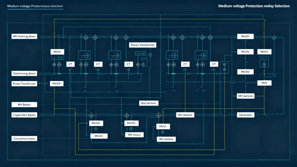
- MV incoming feeders
- Outgoing feeders
- Power transformers (MV/HV)
- Bus sections
- Motors (MV)
- Capacitor banks
- Generator connections
Each application has different protection requirements. A feeder relay needs overcurrent and earth fault protection. A transformer relay may need differential protection plus thermal monitoring.
What Should You Know Before Selecting an MV Protection Relay?
System Voltage and Frequency
Start by confirming the system voltage and frequency. These are fundamental parameters that affect relay input ratings and measurement accuracy.
Check these items:
- Rated voltage (e.g., 11 kV, 33 kV, 66 kV)
- Maximum system voltage (may exceed nominal)
- System frequency: 50 Hz or 60 Hz
- Single-phase or three-phase configuration
Important: System voltage is not the same as relay auxiliary supply voltage. The relay may require 110 VDC or 220 VAC for its internal circuits, independent of the primary system voltage.
Maximum Load Current
Collect load current data for the protected circuit. Do not rely solely on equipment nameplate ratings. Real operating conditions often differ from design values.
Gather these current values:
- Normal operating current
- Maximum continuous current
- Transformer full-load rating
- Motor starting current (if applicable)
- Expected future load growth
A relay set too low will nuisance-trip during normal load variations. A relay set too high may fail to detect genuine overload conditions.
Short-Circuit Current
Short-circuit current levels determine relay measuring range, CT selection, and protection sensitivity. You need both maximum and minimum fault current values.
Confirm these fault current parameters:
- Maximum three-phase short-circuit current
- Minimum fault current (often single-phase-to-ground)
- Phase-to-phase fault current
- Single-line-to-ground fault current
The maximum fault current affects CT saturation risk and relay withstand capability. The minimum fault current determines whether the relay can detect faults at the far end of the protected zone. If the relay cannot see the minimum fault, protection will fail.
Identify the Equipment to Be Protected
Different equipment types require different protection functions. The table below shows typical protection for common MV substation assets.
| MV Substation Equipment | Typical Protection Functions |
|---|---|
| Incoming feeder | Overcurrent (50/51), earth fault (50N/51N), directional protection (67/67N) |
| Outgoing feeder | Overcurrent (50/51), earth fault (50N/51N) |
| Power transformer | Differential (87T), overcurrent (50/51), earth fault (50N/51N), thermal |
| Busbar | Differential protection (87B) or arc flash protection |
| MV motor | Overload (49), short circuit (50/51), earth fault, phase loss |
| Capacitor bank | Overcurrent, unbalance, overvoltage |
| Generator feeder | Differential, overcurrent, reverse power, earth fault |
MV Feeder Protection
Feeders typically use overcurrent protection (ANSI 50/51) and earth fault protection (50N/51N). Directional overcurrent (67/67N) is required for ring networks or parallel feeders where fault current can flow in either direction.
Instantaneous overcurrent (50) clears severe faults quickly. Time-delay overcurrent (51) coordinates with downstream protection and handles overload conditions.
MV Transformer Protection
Transformers are expensive assets that need comprehensive protection. A typical transformer protection scheme includes:
- Differential protection (87T) – primary protection for internal faults
- Overcurrent protection (50/51) – backup protection
- Earth fault protection (50N/51N)
- Temperature monitoring
- Buchholz relay (for oil-filled transformers)
The relay settings must account for transformer inrush current. Without proper inrush blocking, the differential relay may trip during energization.
MV Busbar Protection
Busbar faults are severe events that can cause extensive damage. Protection options include:
- Bus differential protection (87B) – high-speed protection for bus zones
- Arc flash protection – fast light-based detection for switchgear
- Breaker failure protection – backup if the primary breaker fails to clear
Arc flash protection relays are often more cost-effective than full bus differential schemes, particularly for retrofit projects.
Key Criteria for Medium Voltage Protection Relay Selection
1. Protection Functions
Select functions based on the equipment type and system configuration. Common functions include:
| ANSI Code | Function |
|---|---|
| 50 | Instantaneous overcurrent |
| 51 | Time-delay overcurrent |
| 50N/51N | Earth fault |
| 67/67N | Directional overcurrent |
| 87T | Transformer differential |
| 87B | Bus differential |
| 27 | Undervoltage |
| 59 | Overvoltage |
| 81U/81O | Under/over frequency |
| 46 | Negative sequence |
| 49 | Thermal overload |
| 50BF | Breaker failure |
Do not add functions just because they exist in the relay catalogue. Select only what the system requires. Extra functions increase configuration complexity and potential for misoperation.
2. CT and PT Compatibility
CT and PT parameters must match the relay inputs. Mismatched transformers are one of the leading causes of protection failure.
CT Ratio and Class
Select a CT ratio that provides adequate secondary current for the relay. Common ratios are 100/5 A, 200/5 A, 400/5 A, and 600/1 A. The relay’s input range must cover the CT secondary output.
Protection-grade CTs (P class) are required for relay inputs. Metering-grade CTs are not acceptable for protection applications. Check CT burden and accuracy class to ensure the CT can drive the relay input without saturation.
CT Saturation
CT saturation occurs when the fault current exceeds the CT’s capability. Saturation distorts the secondary current waveform, causing the relay to underreach or fail to operate.
For high fault-current systems, select CTs with higher saturation limits or choose relays with anti-saturation sampling algorithms. Check the CT knee-point voltage against the required relay performance.
PT/VT Requirements
If you need voltage-dependent functions (undervoltage, overvoltage, frequency, directional, distance, sync-check), verify the PT/VT ratio and accuracy class. The relay must receive a voltage signal that accurately represents the primary system voltage.
3. Protection Sensitivity and Setting Range
The relay must detect the minimum expected fault current while remaining stable during normal operating conditions. This balance is critical for reliable protection.
Consider these parameters when setting the relay:
- Pickup current
- Time delay
- Instantaneous setting
- Time-current curve characteristics
- Minimum fault current at the zone endpoint
If the pickup is set too high, the relay will not see low-magnitude faults. If set too low, it will nuisance-trip on load variations or motor starting.
4. Protection Coordination
Coordination ensures that the nearest relay to the fault trips first. Upstream relays provide backup if the primary relay fails.
Coordination requires analysis of time-current curves for series devices. Allow adequate grading margins between upstream and downstream relays. The coordination margin accounts for:
- Relay operating time tolerances
- Breaker interrupting time
- CT errors
- Safety margin
The engineer performing the coordination study must be familiar with the overall relay-breaker characteristics.
Relay → Circuit Breaker → Upstream Protection is the typical coordination hierarchy. Verify this chain for every protection zone.
Which Protection Functions Are Commonly Required in an MV Substation?
Overcurrent Protection — ANSI 50/51
Overcurrent protection is the foundation of MV protection. It applies to feeders, transformers, and motors.
- ANSI 50: Instantaneous trip for severe faults
- ANSI 51: Time-delay trip with inverse or definite-time characteristics
The 51 curve type depends on the application. Extremely inverse curves suit generator protection. Very inverse curves suit transformer protection. Long-time curves suit motor protection.
Earth Fault Protection — 50N/51N
Earth fault protection is essential for grounded systems. The configuration depends on the system grounding method:
- Solidly grounded: High fault currents, standard earth fault relays
- Resistance grounded: Lower fault currents, sensitive earth fault relays required
- Ungrounded: No earth fault current, requires voltage-based detection
Residual CT or zero-sequence CT sampling is used for low-current earth faults. For resistance-grounded systems, specify sensitive earth fault protection to ensure minor faults are detected.
Directional Overcurrent Protection — 67/67N
Directional protection is required where fault current can flow in either direction. Typical applications include:
- Ring networks
- Parallel feeders
- Systems with distributed generation
- Bidirectional power flow
Directional relays use voltage reference to determine power flow direction. They trip only when fault current flows in the selected direction, preventing unnecessary tripping of healthy circuits.
Transformer Differential Protection — 87T
Differential protection compares current entering and leaving the transformer. It trips for internal faults within the protected zone.
87T requires careful CT matching and polarity checking. The relay must accommodate transformer turns ratio, vector group, and CT ratio differences. Inrush current blocking is essential to prevent nuisance tripping during transformer energization.
Bus Differential Protection — 87B
Bus differential protection provides high-speed protection for busbar faults. It operates by comparing currents entering and leaving the bus zone.
High-impedance differential and numerical schemes are available. Choose based on the bus configuration and fault current levels. Numerical bus differential relays offer greater flexibility and are easier to commission.
Voltage and Frequency Protection
Voltage and frequency protection functions include:
- ANSI 27: Undervoltage – protects motors from voltage dips
- ANSI 59: Overvoltage – protects capacitors and other equipment
- ANSI 81U: Underfrequency – for load shedding
- ANSI 81O: Overfrequency – for generator protection
These functions are often required for generator connections or systems with distributed generation.
Numerical MV Protection Relay vs Conventional Relay
Numerical relays offer significant advantages over conventional electromechanical or static relays for MV substations. The table below compares key features.
| Feature | Conventional Relay | Numerical MV Relay |
|---|---|---|
| Protection functions | Limited to fixed set | Multiple, configurable |
| Measurement | Basic | Advanced, multiple quantities |
| Event recording | Limited or none | Full event logging |
| Fault recording | Limited or none | Detailed fault records |
| Communication | None or basic | Multiple protocols (IEC 61850, Modbus, DNP3) |
| SCADA integration | Basic | Full integration |
| Setting flexibility | Fixed or limited | Fully adjustable |
| Substation automation | Limited | Full support |
| Cybersecurity | Not applicable | Built-in features |
When Should You Choose a Numerical MV Protection Relay?
Numerical relays are recommended for:
- Complex MV substations with multiple protection zones
- Applications requiring multiple protection functions
- SCADA integration and remote monitoring
- Fault recording and event analysis
- Future system expansion and change
- Compliance with modern utility requirements
For simple, fixed applications, a conventional relay may be sufficient. However, the additional cost of a numerical relay is often justified by its flexibility, diagnostics, and communication capabilities.
Communication Requirements for an MV Substation Relay
Common Communication Protocols
Select a relay that supports the protocols used by your substation automation system. Common protocols include:
- IEC 61850 – Modern digital substation standard
- Modbus RTU – Widespread in industrial applications
- Modbus TCP – Ethernet-based industrial protocol
- DNP3 – Common in utility SCADA
- IEC 60870-5-103/104 – Utility grid standard
IEC 61850 provides interoperability between devices from different manufacturers. It is the preferred standard for new intelligent substations.
Integration With SCADA and Substation Automation
Determine whether the relay needs to connect to:
- SCADA system
- PLC
- HMI
- RTU
- Substation automation system
The relay must exchange data with these systems for remote monitoring, alarm annunciation, fault reporting, and parameter adjustment. Check that the relay supports the required protocols and provides the necessary data objects.
Digital Inputs and Outputs
Confirm the relay’s I/O configuration meets your requirements:
- Binary inputs – breaker status, external protection signals, interlocking
- Binary outputs – trip command, alarm, control signals
If the standard I/O count is insufficient, specify a relay with expansion modules. Some numerical relays support modular I/O configuration to match project needs.
Check the MV Protection Relay’s Installation Requirements
Auxiliary Power Supply
Verify the relay’s auxiliary power requirements against available site supply:
| Supply Type | Typical Values |
|---|---|
| DC | 24 V, 48 V, 110 V, 220 V |
| AC | 110 V, 220 V |
Panel Installation
Check panel mounting dimensions and terminal arrangement:
- Panel cutout dimensions
- Rack mounting (19-inch standard)
- DIN rail mounting
- Terminal spacing and wiring access
Select a relay that fits the available panel space. Some relays are designed specifically for compact switchgear and offer a smaller footprint.
Environmental Conditions
Match the relay’s environmental ratings to site conditions:
| Condition | Check |
|---|---|
| Ambient temperature | Operating range (-25°C to +70°C typical) |
| Humidity | Condensation risk |
| Dust | IP rating required |
| Vibration | Switchgear location |
| Electromagnetic interference | EMC immunity requirements |
Relays in outdoor or harsh environments require higher ingress protection and wider temperature tolerance. Indoor control room installations have less demanding requirements.
Standards to Check When Selecting an MV Protection Relay
All relays should comply with relevant international standards. The required standards depend on project specifications and local grid codes.
Core standards include:
- IEC 60255 series – General standard for measuring relays and protection equipment. IEC 60255-1:2022 covers common requirements and test methods.
- IEC 61850 – Communication and automation standard for substations.
- IEEE/ANSI C37 series – Power system protection standards, including ANSI function codes.
- IEC 61000 series – Electromagnetic compatibility requirements.
Check whether the project requires additional certifications for marine, railway, or specific utility applications. These applications may have enhanced requirements beyond the IEC 60255 baseline.
Note: The standards required depend on the project specification, utility requirements, and country-specific regulations. Verify applicable standards before final selection.
Step-by-Step Medium Voltage Protection Relay Selection Process
Follow these steps to select an MV protection relay systematically.
| Step | Description |
|---|---|
| Step 1 | Define the protected equipmentIdentify whether the relay protects a feeder, transformer, motor, generator, or busbar. |
| Step 2 | Confirm system voltage and frequencyVerify rated voltage, maximum voltage, and frequency (50/60 Hz). |
| Step 3 | Determine normal and maximum load currentCollect steady‑state load, peak load, and overload data. |
| Step 4 | Obtain maximum and minimum fault currentGet three‑phase and single‑phase fault current values. |
| Step 5 | Check CT/PT specificationsVerify CT ratio, class, burden, and PT ratio. |
| Step 6 | Determine required protection functionsSelect ANSI functions based on equipment and system. |
| Step 7 | Perform protection coordinationComplete time‑current curve coordination with upstream/downstream devices. |
| Step 8 | Define communication and SCADA requirementsCheck protocol support and I/O requirements. |
| Step 9 | Check I/O and auxiliary power requirementsConfirm binary inputs/outputs and auxiliary supply voltage. |
| Step 10 | Verify standards and environmental requirementsEnsure relay meets applicable standards and site conditions. |
| Step 11 | Compare suitable relay modelsShortlist relays that meet all requirements. |
| Step 12 | Confirm settings and protection schemeValidate relay settings and coordinate with the overall scheme. |
Example of MV Protection Relay Selection for a 33 kV Substation
This example shows a practical selection process for a 33 kV distribution feeder.
System Data:
| Parameter | Value |
|---|---|
| Voltage | 33 kV |
| Frequency | 50 Hz |
| CT ratio | 400/5 A |
| Maximum load current | 280 A |
| Short-circuit current | 12.5 kA |
| Earthing | Solidly grounded |
| SCADA required | Yes |
Step 1: Determine Protection Functions
For a feeder in this system, standard protection includes:
- Overcurrent protection (50/51)
- Earth fault protection (50N/51N)
- Directional overcurrent (67/67N) – required if the feeder is in a ring or parallel arrangement
Step 2: Check CT Compatibility
The 400/5 A CT output is 5 A at rated primary current. The relay input range must accommodate this level. At 12.5 kA fault current, the CT secondary current is approximately 156 A (assuming linear operation). Check that the CT does not saturate at this level and that the relay input range extends to this value.
Verify CT class and burden against relay requirements.
Step 3: Check Relay Settings
Set the 51 pickup above maximum load current with some margin. For 280 A load, a pickup of approximately 350–400 A is typical (20–40% margin). Check that this setting is below the minimum fault current at the feeder end to ensure sensitivity.
Step 4: Check Communication
Since SCADA is required, select a relay that supports the specified protocol. If the substation uses IEC 61850, choose a relay with native IEC 61850 support.
Step 5: Final Relay Selection
Select a numerical relay that meets all requirements. If the application is standard and no SCADA is required, an entry-level relay with basic overcurrent and earth fault functions may be sufficient.
Common Mistakes When Selecting an MV Protection Relay
Choosing a Relay Based Only on Voltage Rating
Voltage rating is one parameter among many. Load current, fault current, CT matching, and protection functions are equally important.
Ignoring CT Saturation
CT saturation at high fault currents can cause relay misoperation. Verify CT saturation limits and select appropriate CTs or relays with anti-saturation algorithms.
Selecting Pickup Settings Without a Coordination Study
Pickup settings must coordinate with upstream and downstream relays. Without a coordination study, nuisance tripping or loss of selectivity is likely.
Using the Same Relay for Every MV Feeder
Each feeder has different load and fault conditions. Settings and even relay models may need to vary. Do not apply a one-size-fits-all approach.
Ignoring the Grounding System
Earth fault protection depends on the system grounding method. Use sensitive earth fault protection for resistance-grounded systems. For ungrounded systems, earth fault detection requires different methods (voltage-based).
Forgetting SCADA and Communication Requirements
If the relay cannot communicate with SCADA, remote monitoring and control are impossible. Communication capability is often overlooked in initial selection.
Selecting a Relay Without Considering Future Expansion
System loads and fault levels may change over time. Select a relay that can accommodate future changes. Numerical relays with modular I/O and adjustable settings offer better adaptability.
MV Protection Relay Selection Checklist
Use this checklist to confirm all parameters before finalizing a relay model.
| Parameter | What to Check |
|---|---|
| System voltage | Rated and maximum voltage |
| Frequency | 50/60 Hz |
| Load current | Normal and maximum |
| Fault current | Maximum and minimum |
| CT | Ratio, class, burden, saturation |
| PT/VT | Ratio and input requirements |
| Protection functions | Required ANSI codes |
| Coordination | Upstream/downstream settings |
| Communication | IEC 61850, Modbus, DNP3, etc. |
| I/O | Binary inputs and outputs |
| Power supply | AC or DC auxiliary supply |
| Installation | Panel dimensions, terminals |
| Environment | Temperature, humidity, EMC |
| Standards | IEC/IEEE/local requirements |
FAQ About MV Protection Relay Selection
What is an MV protection relay?
An MV protection relay monitors current, voltage, and frequency in medium voltage systems. It detects faults and sends trip commands to circuit breakers to isolate faulty equipment.
How do I select a protection relay for a medium voltage substation?
Start by defining the protected equipment, system voltage, load current, and fault current. Then check CT/PT compatibility, select protection functions, complete coordination, and verify communication and installation requirements.
What protection functions are required for an MV feeder?
A basic MV feeder typically requires overcurrent protection (50/51) and earth fault protection (50N/51N). Directional overcurrent (67/67N) may be needed for ring networks or parallel feeders.
How does CT ratio affect MV relay selection?
The CT ratio determines the secondary current level supplied to the relay. A ratio that is too large reduces sensitivity. A ratio that is too small may exceed the relay input range or cause saturation.
Do all MV substations need numerical protection relays?
No. Simple substations with standard overcurrent and earth fault requirements may use conventional relays. However, numerical relays provide superior flexibility, diagnostics, and communication capability, making them the preferred choice for most new projects.
What communication protocols are commonly used for substation relays?
IEC 61850, Modbus RTU, Modbus TCP, DNP3, and IEC 60870-5-103/104 are commonly used. IEC 61850 is the standard for modern digital substations.
What is the difference between an MV feeder relay and a transformer protection relay?
A feeder relay provides overcurrent and earth fault protection for lines. A transformer protection relay includes differential protection (87T), overcurrent protection, earth fault protection, and thermal monitoring to address transformer-specific risks.
When is directional overcurrent protection required in an MV substation?
Directional overcurrent protection is required where fault current can flow in either direction. This occurs in ring networks, parallel feeders, and systems with distributed generation or bidirectional power flow.
Conclusion
Selecting a protection relay for a medium voltage substation is not a simple model-matching exercise. It requires a systematic review of equipment type, system parameters, fault levels, CT/PT performance, protection functions, coordination, communication, and installation conditions.
Following a structured selection process reduces the risk of miscoordination, nuisance tripping, and protection failure. It also ensures that the relay meets current requirements and can adapt to future system changes.
If you are selecting an MV protection relay for a feeder, transformer, motor, or complete medium voltage substation, provide the system voltage, CT ratio, load current, fault level, required protection functions, and communication requirements. A suitable relay configuration can then be evaluated against the project requirements.
References and Technical Sources
- IEC 60255-1:2022 – Measuring relays and protection equipment – Part 1: Common requirements
- IEC 61850-7-4:2018 – Communication networks and systems for power utility automation
- IEEE C37.112-2018 – Standard for Inverse Time Characteristic Equations for Overcurrent Relays
- IEEE C37.2-2008 – Standard for Electrical Power System Device Function Numbers
- CIGRE Working Group B5.04 – Power System Protection Coordination Guidelines
- IEC 61000-6-5:2019 – Electromagnetic compatibility – Immunity requirements for power system equipment
- IEC 60255-121:2014 – Functional requirements for distance protection
- IEC 60255-151:2009 – Functional requirements for over/under current protection



About Author

Hello, I'm Leno Zhang. I have 15 years of experience in the power relay protection industry with extensive pre-sales and after-sales project experience. Our company specializes in various complete sets of relay protection and automation equipment. I can assist customers in solving all practical on-site project challenges and provide optimal integrated solutions.
Tell Us Your Requirement
High Quality
Stable performance, reliable design, ensuring safe operation for power system protection and grid stability.
Fast Delivery
Timely delivery to support your urgent orders and project schedules efficiently and professionally at any time.
Best Warranty
Professional Warranty: Reliable after-sales support for stable relay protection and long-term customer satisfaction.