

-
Leon Zhang sales consultant
-
Email: zxl635973785@gmail.com
-
Phone/WhatsApp: +86 13655813266
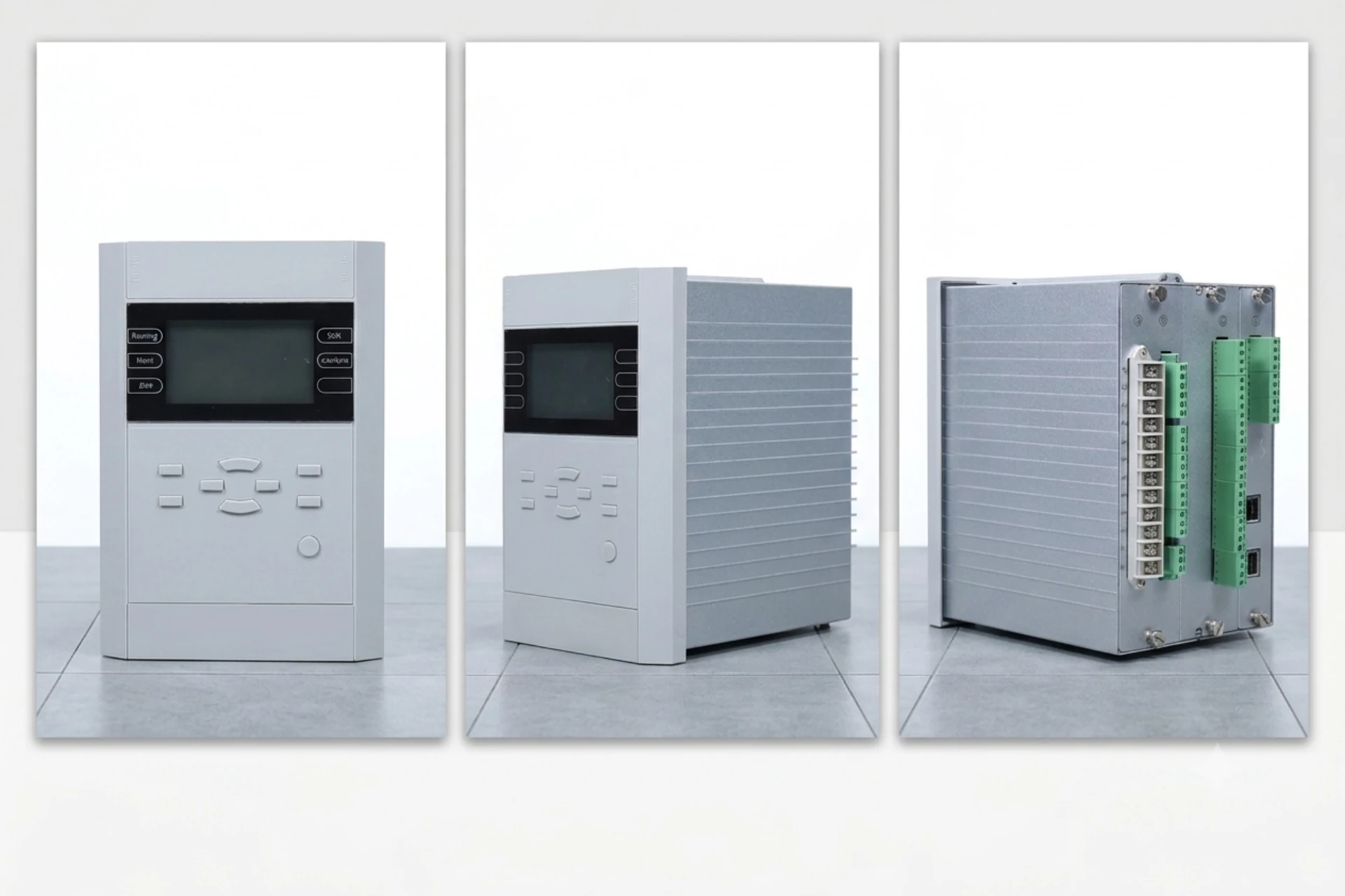
Transformer Protection Devices: Complete List with ANSI Codes
Transformer protection devices cover every fault a unit can see, from winding short circuits to rising gas pressure. Written by Leon Zhang, Protection Application Engineer · Technical review by Li Ming, Electrical Engineer · Last reviewed September 2026
Power Transformer Protection Devices are electrical protection and monitoring equipment used to detect, isolate and manage faults and abnormal operating conditions in power transformers. A complete transformer protection system may include transformer differential protection relays, overcurrent and earth fault relays, Buchholz relays, temperature monitoring devices, pressure protection, oil level monitoring and other protection equipment.
The required protection devices depend on the transformer rating, voltage level, winding configuration, grounding method, fault level and the importance of the transformer within the power system. Main protection is typically used to detect internal transformer faults, while backup and mechanical protection functions help address external faults, overload, overheating, gas generation and other abnormal conditions.
The sections below take each function in turn, the fault it answers to, and how to pick the unit. They are written for EPC contractors, substation engineers and procurement teams comparing protection equipment for new builds, upgrades and retrofits.
What Counts as a Transformer Protection Device?
The set splits into electromechanical, solid-state and numerical hardware. All three cover the same functions; they differ in cost, accuracy and how much setting work they need. In practice the transformer protection device types below are what a spec sheet lists: the differential relay, the overcurrent and earth fault functions, and the mechanical and non-electrical devices that watch oil and winding condition.
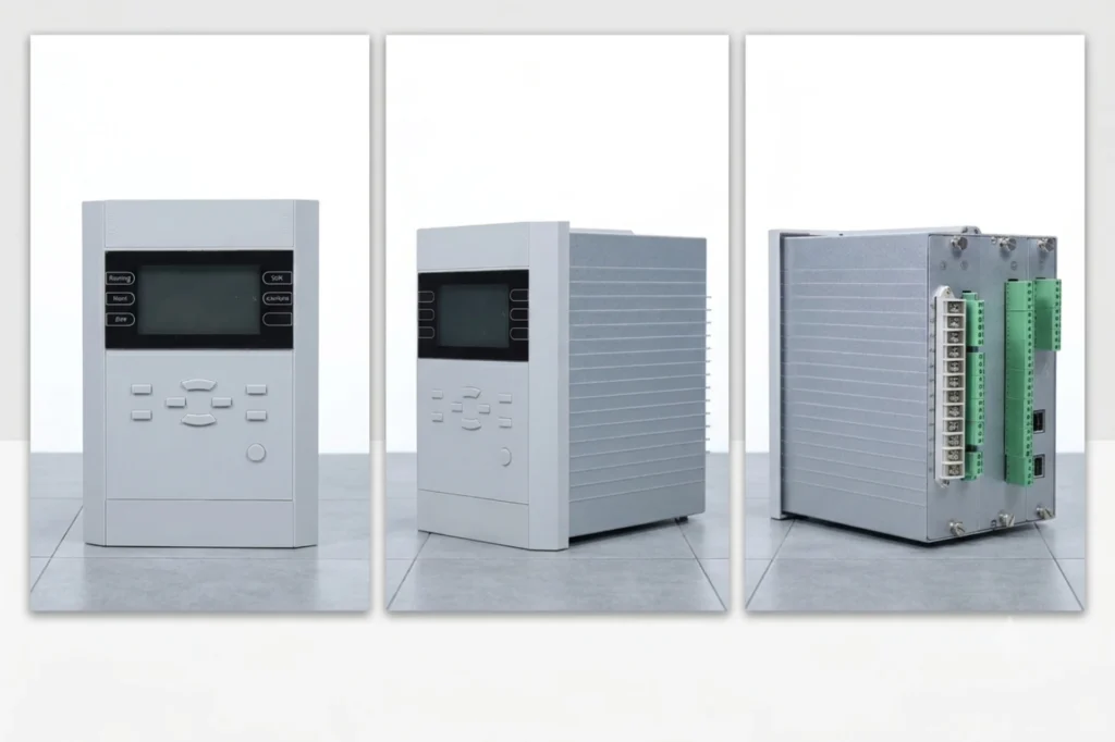
Power transformer protection devices are a combination of electromechanical, solid-state, or numerical relays, sensors, and mechanical devices that work together to detect abnormal conditions and faults in a power transformer and initiate appropriate action, typically tripping the circuit breaker to isolate the transformer or sending alarms for operator intervention.
These devices monitor parameters such as current, voltage, temperature, oil level, gas accumulation, and pressure. Modern protection systems integrate multiple protection functions into a single numerical relay (IED), providing faster operation, enhanced reliability, and advanced communication capabilities for substation automation.
What Does a Power Transformer Protection System Protect Against?
A full transformer protection system guards against:
- Internal Electrical Faults: Winding short circuits (inter-turn, phase-to-phase, phase-to-ground), core faults, and bushing failures.
- External System Faults: Downstream short circuits and earth faults that cause through-fault currents.
- Abnormal Operating Conditions: Overload, overheating, overexcitation (V/Hz), overvoltage, undervoltage, low oil level, and cooling system failure.
- Mechanical Issues: Internal arcing, pressure buildup, and oil decomposition.
- Incipient Faults: Early-stage insulation deterioration detected via gas accumulation or dissolved gas analysis.
Transformer Protection Device Types
Transformer Differential Protection Relay: 87T
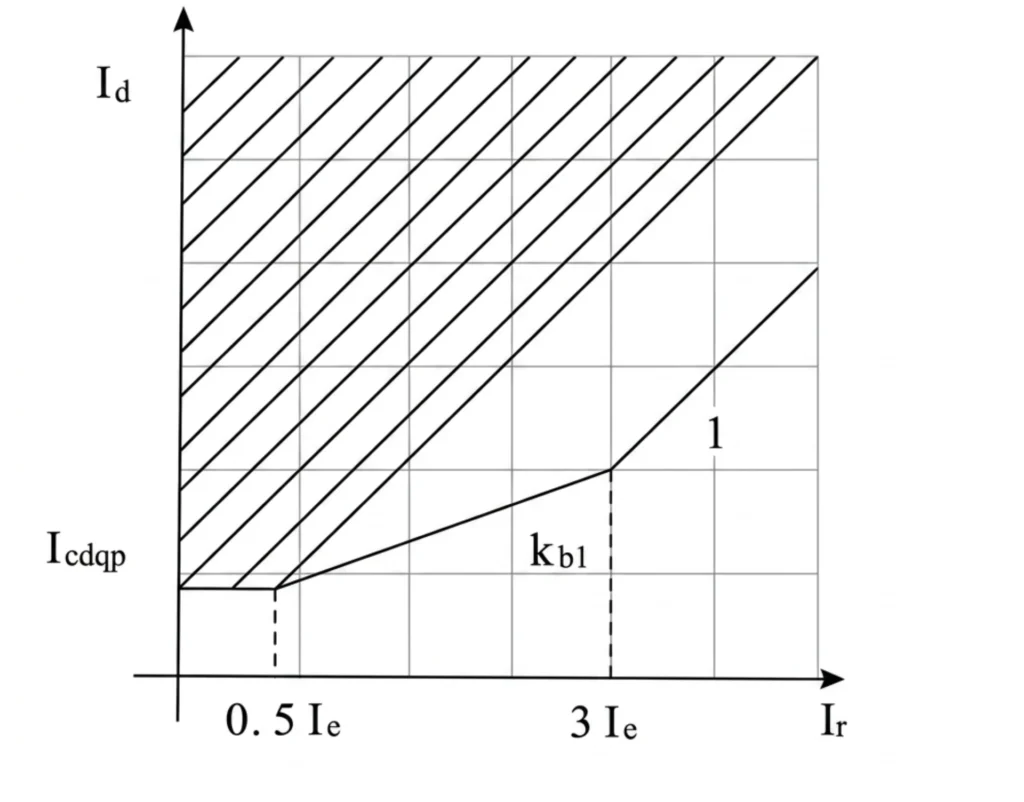
The primary protection within a complete transformer protection system for large transformers compares currents entering and leaving the transformer. Under normal conditions, they are balanced (minus excitation current).
An internal fault creates an unbalance, and the relay trips instantly. Features include harmonic restraint (2nd harmonic for inrush, 5th harmonic for overexcitation) and percentage slope characteristics to ensure stability during through‑faults.
For detailed CT compensation, differential protection principles and setting calculations, see our Transformer Differential Protection Guide.
Overcurrent Protection Relay: 50/51
- 50 (Instantaneous Overcurrent): Fast clearing for severe phase faults.
- 51 (Time-Delay Overcurrent): Backup protection with inverse-time characteristics (IEC or IEEE curves) for coordination with downstream devices.
Essential for both primary and backup transformer protection.
Earth Fault Protection Relay: 50N/51N
- 50N (Instantaneous Earth Fault): Detects high-magnitude ground faults.
- 51N (Time-Delay Earth Fault): Sensitive detection of low-magnitude ground faults via residual current measurement.
Critical for detecting winding-to-ground faults, especially in grounded systems.
Restricted Earth Fault Protection: 64REF
A high‑sensitivity earth fault protection, one essential piece of transformer protection equipment, is specifically designed for the transformer winding zones. It compares neutral current with phase currents and provides fast clearing for earth faults within the protected zone. Often used in conjunction with 87T for enhanced ground fault sensitivity, especially in solidly grounded systems.
Overexcitation Protection: 24
Monitors the Volts/Hertz (V/Hz) ratio. When V/Hz exceeds design limits, the core saturates, causing excessive magnetizing current, heating, and vibration. Mandatory for generator step-up transformers and recommended for large power transformers where overexcitation risk exists.
Overvoltage and Undervoltage Protection: 59/27
- 59 (Overvoltage): Protects insulation from sustained high voltages caused by load rejection, ferroresonance, or system faults.
- 27 (Undervoltage): Detects voltage sags; used for load shedding and bus transfer schemes.
Thermal Protection: 49
Monitors winding hot‑spot temperature using a thermal model based on load current, ambient temperature, and cooling mode as one of key transformer protection functions. It provides alarm and trip stages to prevent insulation aging and failure due to sustained overloads. Replaces traditional bimetal or wax‑type thermal devices with more accurate electronic modeling.
Buchholz Relay: 63
A mechanical relay in the oil pipe between the main tank and conservator. It detects:
More on the gas path and the trip logic that follows: Buchholz relay protection.
- Slow gas accumulation (alarm): Minor arcing, insulation breakdown, or low oil.
- Sudden oil surge (trip): Severe internal fault with rapid pressure wave.
Mandatory for oil-immersed transformers with conservator tanks.
Pressure Relief Protection
A mechanical device that operates when internal tank pressure exceeds a set threshold due to sudden gas generation from an internal fault. Provides fast mechanical tripping independent of electrical relays. Essential for preventing tank rupture and oil fire.
Oil Level and Temperature Monitoring
- Oil Level Gauge: Monitors oil level in the conservator or main tank; provides low-level alarm.
- Winding Temperature Indicator (WTI) / Oil Temperature Indicator (OTI): RTD-based sensors (PT100) providing analog inputs to relays and SCADA systems for continuous monitoring and alarm/trip functions.
Transformer Protection Device List
Each row is one entry in the transformer protection device list, with the ANSI device number, the function it performs and the condition that puts it in trip or alarm. The order follows ANSI/IEEE C37.2 rather than the sequence most manufacturers use in their catalogues, so the table doubles as your ANSI code lookup.
| Protection Device | ANSI Code | Main Function | Typical Fault / Condition |
|---|---|---|---|
| Transformer Differential Relay | 87T | Main electrical protection | Internal faults |
| Overcurrent Relay | 50/51 | Backup protection | Short circuit / overload |
| Earth Fault Relay | 50N/51N | Ground fault protection | Earth faults |
| Restricted Earth Fault | 64REF | Sensitive winding earth fault protection | Internal earth faults |
| Overexcitation Relay | 24 | V/Hz protection | Core overheating |
| Overvoltage Relay | 59 | High-voltage protection | Overvoltage |
| Undervoltage Relay | 27 | Low-voltage protection | Undervoltage |
| Thermal Protection | 49 | Thermal monitoring | Overload / overheating |
| Buchholz Relay | 63 | Gas and oil-flow protection | Internal oil-filled transformer faults |
| Pressure Relief Device | 63 | Pressure protection | Internal pressure rise |
| Oil Level Monitor | 71 | Oil level monitoring | Oil leakage / low oil |
| Temperature Monitor | 49 | Temperature monitoring | Winding/oil overheating |
Main Protection vs Backup Protection
| Aspect | Main Protection | Backup Protection |
|---|---|---|
| Purpose | Primary line of defense for the protected zone. | Operates if main protection fails or is unable to clear. |
| Speed | Instantaneous or very fast (e.g., 87T trips in < 2 cycles). | Time-delayed to allow main and downstream protection to operate first. |
| Zone | Zone-specific (e.g., transformer zone). | Wider zone (e.g., covers transformer and connected system). |
| Typical Devices | 87T, 64REF, Buchholz (63), pressure relief. | 51 overcurrent, 51N earth fault. |
| Redundancy | No backup within its zone. | Provides redundancy for transformer and downstream protection. |
Key Principle: Backup protection must coordinate with main protection and downstream devices to ensure selective fault clearing.
Transformer Protection Devices by ANSI Code
ANSI codes for transformer protection come from the device function numbers in ANSI/IEEE C37.2. Protection schemes vary based on transformer size, voltage level, and criticality.
Medium Voltage Power Transformer (≤ 33 kV, < 10 MVA)
- Typical Protection: Overcurrent (51/50) + Earth Fault (51N) + Buchholz (63 for oil-filled) + Thermal (49) + Temperature Monitoring.
- Differential (87T): Usually optional; cost-benefit analysis typically favors overcurrent only.
- Application: Distribution substations, industrial plants, renewable generation step-up.
High Voltage Power Transformer (66 kV – 220 kV, 10 – 100 MVA)
- Typical Protection: Differential (87T) + Overcurrent (51/50) + Earth Fault (51N) + Restricted Earth Fault (64REF) + Buchholz (63) + Thermal (49) + Overexcitation (24).
- Voltage Protection (27/59): Recommended.
- Application: Transmission substations, large industrial facilities.
Large Power Transformer (> 220 kV, > 100 MVA)
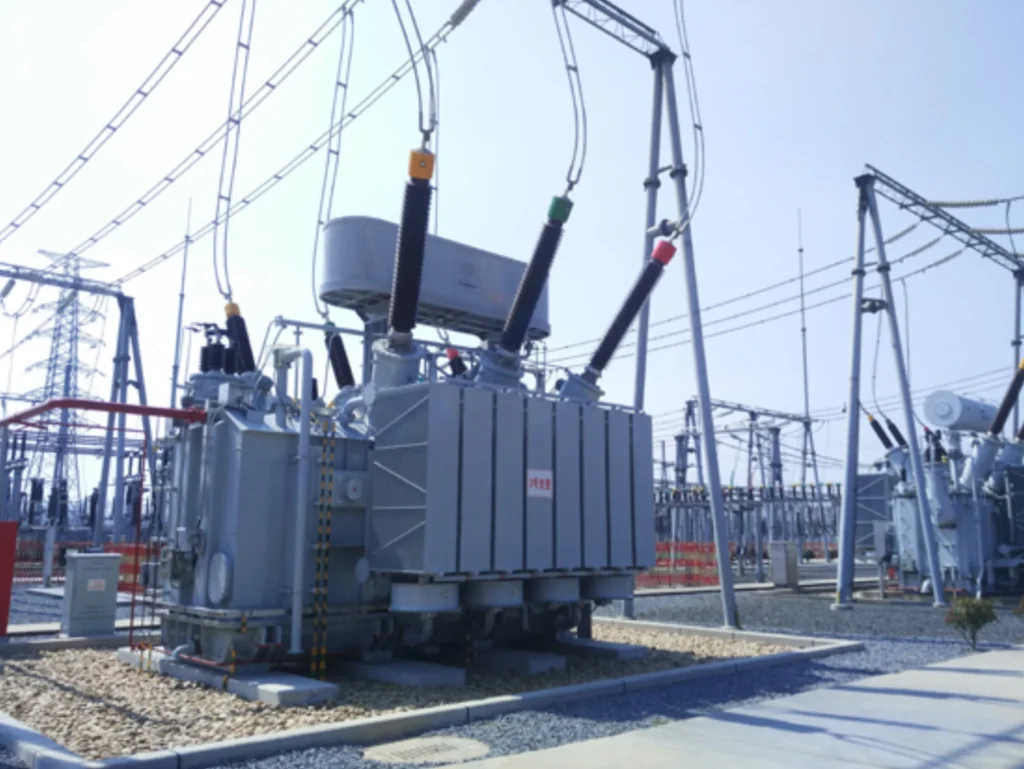
- Typical Protection: Dual differential relays (redundant) + Overcurrent (51) + Earth Fault (51N) + Restricted Earth Fault (64REF) + Buchholz (63) + Pressure Relief + Overexcitation (24) + Overvoltage (59) + Thermal (49) + Cooling Control.
- Redundancy: Two independent protection panels with separate CTs and DC supplies.
- Application: EHV transmission networks, generator step-up (GSU), bulk power substations.
Matching Devices to Fault Types
| Fault / Condition | Primary Device | Backup Device |
|---|---|---|
| Inter-turn fault | 87T | 51 |
| Phase-to-phase fault | 87T / 50 | 51 |
| Winding-to-earth fault | 87T / 51N / 64REF | 51N |
| Core fault | Buchholz (63) / DGA | None |
| Bushing fault | 87T / 50 | 51 |
| External phase fault | Downstream protection | 51 |
| External earth fault | Downstream earth relay | 51N |
| Overload | 49 (Thermal) | Cooling control |
| Overheating | 49 / OTI/WTI | Cooling control |
| Overexcitation | 24 | 59 |
| Overvoltage | 59 | 87T (stability check) |
| Undervoltage | 27 | Load shedding |
| Low oil level | Buchholz (63) alarm | None |
| Pressure buildup | Pressure relief | 63 (surge) |
For a detailed explanation of transformer fault types, see Transformer Fault Types: Causes, Symptoms and Protection Methods.
Digital and Numerical IEDs
Numerical Protection Relay: Function Summary
| Function | ANSI | Key Specifications | Procurement Checklist |
|---|---|---|---|
| Differential Protection | 87T | Dual-slope restraint (15–30% / 50–80%); 2nd harmonic inrush blocking (15–20%); 5th harmonic overexcitation blocking (30–35%); supports 2 or 3 windings; auto phase-shift compensation. | [ ] 2 or 3 windings? [ ] CT class: 5P20/TPY |
| Overcurrent Protection | 50/51 | 50: pickup 1.5–10 x In, instant trip. 51: IEC or IEEE inverse curves; pickup 0.5–2.5 x In; directional option. | [ ] IEC or IEEE curves? [ ] Directional required? |
| Earth Fault Protection | 50N/51N | 50N: pickup 0.1–5 x In, instant. 51N: residual from phase CTs or neutral CT; inverse curves; sensitivity 5–20%. Directional option. | [ ] Residual source: calculated or neutral CT? [ ] Directional required? |
| Under/Overvoltage | 27/59 | 27: pickup 0.6–0.9 Vn; 59: pickup 1.05–1.3 Vn; definite or inverse time delay. | [ ] 1-phase or 3-phase input? [ ] Alarm, trip, or both? |
| Overexcitation (V/Hz) | 24 | Pickup 1.05–1.2 x rated; inverse-time characteristic. Mandatory for generator step-up transformers. | [ ] Required? (GSU → yes) |
| Thermal Overload | 49 | Thermal model using load current, ambient temp, cooling mode (OA/FA/FOA); alarm + trip stages. | [ ] Cooling classes confirmed? |
| Negative Sequence | 46 | Pickup 10–40%; inverse-time characteristic. Recommended for GSU and unbalanced systems. | [ ] Required for this application? |
Event & Disturbance Recording
- Event Recording: Time-stamped sequence of relay pickups, trips, alarms (500–2000 events). Requires time sync (IRIG-B/NTP).
- Disturbance Recording: COMTRADE-format waveform capture (pre-fault 5–10 cycles, post-fault 10–20 cycles). Minimum 16–32 samples/cycle, 10–20 records storage.
Procurement Checklist:
- □ Event storage capacity ≥ 500 events.
- □ Disturbance recording: COMTRADE format, ≥ 16 samples/cycle, ≥ 10 records.
Communication Protocols
| Protocol | Application | Interface |
|---|---|---|
| IEC 61850 | New digital substations (GOOSE/SV) | Fiber optic |
| IEC 60870-5-103 | European utilities, legacy plants | RS-485 / Fiber |
| Modbus RTU | Simple serial, PLC integration | RS-485 |
| Modbus TCP | Universal Ethernet SCADA | RJ45 Ethernet |
Procurement Checklist:
- □ Primary protocol specified.
- □ Secondary protocols for legacy integration (if needed).
- □ Port types and count confirmed.
- □ Time sync: IRIG-B, NTP, or PTP supported.
Substation Integration
| Integration Level | Capability | Key Requirements |
|---|---|---|
| SCADA | Real-time data (current, voltage, power, status, alarms); remote setting changes; control commands (trip/close). | Protocol selection; cybersecurity (role-based access, password protection). |
| HMI | Local front-panel display or remote PC software; single-line diagram, event lists, waveform retrieval, setting modification. | Confirm local or remote HMI required. |
| Station Automation | Fast inter-tripping, interlocking, auto-transfer logic via GOOSE (IEC 61850); redundant topologies (PRP/HSR) optional. | Specify automation features (bus transfer, load shedding, interlocking). |
| Remote Monitoring | Web server access (HTTP/HTTPS); email/SMS alarm notification; IEC 62443 cybersecurity compliance. | Specify cybersecurity level and remote access method. |
Summary: Digital Relay Selection Checklist
| Category | Item | Confirmed? |
|---|---|---|
| 87T | 2 or 3 windings; CT class 5P20/TPY | ☐ |
| 50/51 | IEC/IEEE curves; directional? | ☐ |
| 50N/51N | Residual source; directional? | ☐ |
| 27/59 | 1-phase/3-phase; alarm/trip | ☐ |
| 24 | Required? (GSU: mandatory) | ☐ |
| 49 | Cooling classes confirmed | ☐ |
| 46 | Required? | ☐ |
| Event Recording | ≥ 500 events; IRIG-B/NTP | ☐ |
| Disturbance Recording | COMTRADE; ≥ 16 samples/cycle | ☐ |
| Communication | Primary protocol; ports; time sync | ☐ |
| SCADA | Protocol; cybersecurity | ☐ |
| HMI | Local front panel / remote software | ☐ |
| Automation | GOOSE; interlocking; auto-transfer | ☐ |
| Remote Monitoring | Web access; email alarm; IEC 62443 | ☐ |
How to Select the Right Devices
Selection of power transformer protection devices requires a systematic approach covering transformer parameters, CT specifications, protection functions, communication, and project standards. The following checklist guides procurement and engineering teams through each decision point.
1. Transformer Rating
| Parameter | What to Specify | Why It Matters |
|---|---|---|
| kVA / MVA | Rated capacity (e.g., 10 MVA, 50 MVA) | Determines if 87T is required (≥ 5 MVA → typically yes). |
| Continuous Load | Expected normal load current | Basis for CT ratio selection and thermal (49) relay settings. |
| Fault Level | Maximum symmetrical short-circuit current (kA) at transformer terminals | Determines overcurrent pickup settings, CT saturation requirements, and breaker interrupting capacity. Obtain from system study. |
Procurement Checklist:
- □ Transformer MVA rating confirmed.
- □ Fault level (kA) provided by system study.
- □ %Z (impedance) from nameplate available for coordination study.
2. Voltage Level
| Voltage Level | Typical Range | Protection Complexity |
|---|---|---|
| LV (Low Voltage) | ≤ 1 kV | Simple: fuses or 51/51N only. |
| MV (Medium Voltage) | 1 kV – 33 kV | Standard: 51/51N + 49 + Buchholz; 87T optional. |
| HV (High Voltage) | 66 kV – 220 kV | Full: 87T + 51/51N + REF + 49 + 24 + Buchholz. |
| EHV (Extra High Voltage) | > 220 kV | Redundant protection, dual relays, advanced communication. |
Procurement Checklist:
- □ HV and LV voltage levels confirmed.
- □ System grounding type (solid, resistance, isolated) specified, which changes the earth fault requirement.
3. Winding Configuration
| Configuration | Relay Impact | Key Requirement |
|---|---|---|
| Two-Winding | Standard differential with 2 CT inputs. | 87T with 2 restraint inputs. |
| Three-Winding | Differential requires 3 CT inputs (one per winding). | 87T with 3 restraint inputs (e.g., SEL-487E, P643). |
| Auto-Transformer | Zero-sequence current flows through neutral. | Requires 87TN (zero-sequence differential) in addition to standard 87T. |
Procurement Checklist:
- □ Winding count confirmed (2 or 3).
- □ If auto-transformer, specify 87TN requirement.
4. CT Parameters
| Parameter | Specification | Decision Guide |
|---|---|---|
| CT Ratio | Primary current based on transformer full-load current; secondary current selected to match relay input. | Choose ratio so HV and LV secondary currents are close (compensation factor < 15%). |
| Secondary Rating | 1A (IEC standard, preferred for long cable runs) or 5A (ANSI standard). | Must match breaker CTs. Use 1A for cable runs > 100m to reduce burden. |
| Accuracy Class | For 87T: 5P20 or TPY (anti-saturation). For 50/51: 10P10 minimum. | TPY required if knee point voltage check indicates saturation risk. |
| Burden (VA) | CT rated VA > relay input + cable burden. | Calculate cable burden based on length and conductor size. |
| Saturation (Vk) | Knee point voltage must exceed max fault secondary voltage. | If Vk insufficient → specify TPY class CTs. |
Procurement Checklist:
- □ CT ratio calculated and checked for HV/LV secondary current match.
- □ Secondary rating (1A or 5A) confirmed with breaker CTs.
- □ Accuracy class specified (5P20/TPY for 87T).
- □ CT burden verified against relay input + cable burden.
- □ Knee point voltage calculation performed.
5. Protection Functions
Check each function against project requirements:
| Function | ANSI | When Required | Procurement Decision |
|---|---|---|---|
| Differential | 87T | Transformer ≥ 5 MVA, or critical application. | ☐ Required ☐ Not Required |
| Overcurrent | 50/51 | Always required (primary/backup protection). | ☐ Required |
| Earth Fault | 50N/51N | Always required (grounded or resistance-grounded systems). | ☐ Required |
| Restricted Earth Fault | REF (64) | For enhanced ground fault sensitivity in solidly grounded systems. | ☐ Required ☐ Not Required |
| Overexcitation | 24 | Generator step-up transformers (mandatory); large power transformers (recommended). | ☐ Required ☐ Not Required |
| Thermal Overload | 49 | Strongly recommended for all transformers. | ☐ Required ☐ Not Required |
| Over/Undervoltage | 59/27 | Required for voltage protection and load shedding/auto-transfer schemes. | ☐ Required ☐ Not Required |
Procurement Checklist:
- □ All required functions marked.
- □ For REF, confirm CT configuration (neutral CT + phase CTs required).
- □ For 24, confirm if transformer is generator step-up.
6. Communication
| Protocol | Application | Decision |
|---|---|---|
| IEC 61850 | New digital substations (GOOSE/SV for fast interlocking and process bus). | ☐ Required for new substations |
| Modbus TCP/RTU | Universal SCADA and PLC integration; cost-effective. | ☐ Typically required for all projects |
| IEC 60870-5-103 | European utilities and legacy power plants. | ☐ Required for legacy integration |
Procurement Checklist:
- □ Primary protocol confirmed (e.g., IEC 61850 + Modbus TCP dual stack).
- □ Number and type of communication ports specified (Ethernet, RS-485, fiber).
- □ Time synchronization (IRIG-B, NTP, PTP) confirmed.
7. Project Standards
Compliance requirements vary by project location and application:
| Standard | Typical Application | Decision |
|---|---|---|
| IEC (e.g., IEC 60255, IEC 61850, IEC 60076) | International projects, Europe, Asia, Middle East, Africa. | ☐ IEC compliance required |
| IEEE (e.g., IEEE C37.2, IEEE C57, IEEE C37.112) | North American projects (USA, Canada, Latin America). | ☐ IEEE compliance required |
| Utility Specifications | Specific utility requirements (e.g., National Grid, PG&E, EDF, TNB). | ☐ Utility spec required. Obtain the document. |
| EPC Specifications | Contractor-specific technical requirements for turnkey projects. | ☐ EPC spec provided. Cross-check it against this checklist. |
Procurement Checklist:
- □ Governing standard identified (IEC or IEEE).
- □ Utility or EPC specification document obtained and reviewed.
- □ Relay must comply with utility approval list (if applicable).
Summary: Complete Procurement Checklist
| Category | Parameter | Your Specification | Confirmed |
|---|---|---|---|
| Transformer Rating | MVA | _____ MVA | ☐ |
| Fault level | _____ kA | ☐ | |
| %Z | _____ % | ☐ | |
| Voltage | LV voltage | _____ kV | ☐ |
| HV voltage | _____ kV | ☐ | |
| Winding | Type | ☐ 2-wind ☐ 3-wind ☐ Auto | ☐ |
| CT | Secondary rating | ☐ 1A ☐ 5A | ☐ |
| Accuracy class | ☐ 5P20 ☐ TPY ☐ 10P10 | ☐ | |
| Ratio | _____ / _____ | ☐ | |
| Protection | 87T | ☐ Required ☐ Not Required | ☐ |
| REF | ☐ Required ☐ Not Required | ☐ | |
| 24 | ☐ Required ☐ Not Required | ☐ | |
| 49 | ☐ Required ☐ Not Required | ☐ | |
| 27/59 | ☐ Required ☐ Not Required | ☐ | |
| Communication | Primary protocol | ☐ IEC 61850 ☐ Modbus ☐ IEC 103 | ☐ |
| Standards | Governing standard | ☐ IEC ☐ IEEE | ☐ |
| Utility/EPC spec | Document No.: __________ | ☐ |
What EPC Projects Actually Receive
For EPC contractors, transformer protection delivery goes beyond hardware. It requires complete documentation, engineering support, and testing services. The following checklist defines what suppliers must provide at each project phase.
Technical Documentation
| Document | Format | Purpose |
|---|---|---|
| Datasheet | PDF + Excel | Complete relay specs for engineering integration. |
| Protection Function List | ANSI codes, setting ranges, default values. | |
| Wiring Diagram | CAD (DWG/DXF) + PDF | External connections: CT/VT, I/O, power, comms. |
| Terminal Diagram | CAD + PDF | Physical terminal arrangement for panel design. |
| Communication Protocol & Point List | PDF + ICD/CID (IEC 61850) | Supported protocols and data mapping. |
| Setting Guide | Step-by-step configuration and logic diagrams. | |
| User Manual | Operation, installation, maintenance. |
Checklist: ☐ All documents requested in RFQ ☐ CAD formats specified ☐ ICD file included for IEC 61850 projects.
Project Engineering Support
| Task | Supplier Responsibility |
|---|---|
| SLD Review | Confirm CT/VT locations, protection zones, relay placement. |
| Relay Selection | Recommend model based on MVA, voltage, windings, protection functions. |
| Protection Configuration | Provide setting templates; assist with coordination calculations. |
| CT/VT Compatibility | Verify ratios, accuracy class (5P20/TPY), burden, knee point voltage. |
| Communication Integration | Provide point list/ICD file; assist with SCADA/station bus integration. |
| Panel Design | Supply dimensions, cutout drawings, terminal schedules. |
Checklist: ☐ Setting calculation support included ☐ CT/VT compatibility check ☐ ICD file provided ☐ Panel drawings delivered.
Factory Acceptance Testing (FAT)
| Test | What Is Verified |
|---|---|
| Visual/Mechanical Inspection | Correct assembly, wiring, labeling. |
| Secondary Injection | Each protection function (87T, 51/51N, REF, 24, 49, 27/59) operates per settings. |
| I/O Test | All binary inputs/outputs correctly wired and functional. |
| Communication Test | Protocols (IEC 61850, Modbus, DNP3) working; data mapping correct. |
| Power Supply Test | Operation under nominal, undervoltage, overvoltage DC conditions. |
Checklist: ☐ FAT scope defined ☐ Procedure approved ☐ FAT witnessed (if required) ☐ Signed FAT report delivered.
Site Acceptance Testing & Commissioning Support
| Test | What Is Verified |
|---|---|
| Visual Inspection | Correct site installation per approved drawings. |
| Secondary Injection (Site) | Settings loaded correctly; functions verified with site wiring. |
| I/O & Trip Circuit Test | Binary I/O functional; breaker trips correctly from each function. |
| Communication Test (Site) | SCADA/HMI/station automation integration verified. |
| Primary Injection | CT ratio, polarity, and relay measurement accuracy under actual current flow. |
| Commissioning Support | On-site engineer assists with final settings and troubleshooting. |
Checklist: ☐ SAT scope included ☐ Primary injection equipment/procedure defined ☐ On-site engineer assigned ☐ SAT report signed before energization.
EPC Scope of Supply: Quick Summary
| Phase | Key Deliverables | Included? |
|---|---|---|
| Documentation | Datasheet, wiring/terminal diagrams, point list/ICD, setting guide, manual | ☐ |
| Engineering | SLD review, relay selection, protection config, CT/VT check, comms integration, panel drawings | ☐ |
| FAT | Visual, secondary injection, I/O, comms, power supply tests + report | ☐ |
| SAT & Commissioning | Site secondary injection, I/O/trip, comms, primary injection + on-site engineer + SAT report | ☐ |
Why Contractors Choose Us
We supply transformer protection devices and relay solutions for EPC contractors, utilities, substations and industrial power projects. Our products are sourced from qualified OEM manufacturing partners and can be selected according to transformer ratings, protection requirements, communication interfaces and project specifications.
Our Product Range
1. Transformer Differential Protection Relay
Core: 87T, the primary protection for internal transformer faults.
Key Features: Dual-slope restraint; 2nd/5th harmonic blocking; supports 2 or 3 windings; auto phase-shift compensation; CT saturation detection.
Application: Large transformers, GSU, critical substations (≥ 5 MVA).
Comms: IEC 61850, Modbus, DNP3.
➡ View product: 87T transformer differential relay →
2. Numerical Transformer Protection Relay
Core: 87T + 50/51 + 50N/51N + 24 + 49 + 27/59, all in one IED.
Key Features: Full protection suite; event & disturbance recording (COMTRADE); multi-protocol communication.
Application: HV/EHV transformers, industrial substations.
Comms: IEC 61850, Modbus TCP/RTU, IEC 103, DNP3.
➡ View product: numerical transformer protection relay →
3. Transformer Backup Protection Relay
Core: 50/51 + 50N/51N for phase and earth fault backup.
Key Features: Instantaneous + inverse-time overcurrent; residual earth fault; directional option; compact and cost-effective.
Application: Backup for power transformers; distribution transformers without 87T.
Comms: Modbus RTU/TCP; IEC 61850 optional.
➡ View product: transformer backup protection relay →
4. Three-Winding Transformer Protection Relay
Core: three-winding 87T, differential with 3 independent restraint inputs.
Key Features: Dedicated 3-winding algorithm; independent ratio/phase compensation per winding; supports tertiary connections.
Application: Three-winding power transformers, auto-transformers with tertiary.
Comms: IEC 61850, Modbus, DNP3.
➡ View Product →Three-Winding Transformer Protection Relay
5. Transformer Protection & Control Panel
Core: Relay + CT/VT interface + breaker control + SCADA/IEC 61850 for a complete panel solution.
Key Features: Full protection relay; test blocks for CT/VT; trip/close controls; SCADA integration; dual DC supply option.
Application: New substations, EPC turnkey projects, retrofits.
Mounting: 19″ rack, switchgear flush-mount, or standalone cubicle.
➡ View Product →Transformer Protection & Control Panel
Quick Selection Guide
| Product | Core Functions | Best For |
|---|---|---|
| Differential Relay | 87T | ≥ 5 MVA transformers |
| Numerical Relay | Full suite (87T + 50/51 + 51N + 24 + 49 + 27/59) | All-in-one protection |
| Backup Relay | 50/51 + 50N/51N | Distribution / backup applications |
| Three-Winding Relay | 3-winding 87T | Three-winding & auto-transformers |
| Protection Panel | Relay + CT/VT + control + SCADA | EPC projects, substations |
For datasheets, application notes, or quotations, contact our engineering team.
Transformer Protection FAQ
What are power transformer protection devices?
Power transformer protection devices are instruments and relays, both electrical and mechanical, that monitor transformer parameters (current, voltage, temperature, oil level, gas, pressure) and initiate alarms or trip commands to isolate the transformer during faults or abnormal conditions, preventing catastrophic damage.
What are the main protection devices used for power transformers?
Main devices: Differential relay (87T), overcurrent relays (50/51), earth fault relays (50N/51N), restricted earth fault relay (64REF), overexcitation relay (24), thermal relay (49), over/undervoltage relays (59/27), Buchholz relay (63), pressure relief device, and oil/winding temperature monitors.
What is the main protection for a power transformer?
Differential protection (87T) is the primary main protection for transformers ≥ 5 MVA. For smaller distribution transformers, overcurrent protection (51) plus fuses often serves as the main protection.
Is a transformer differential relay the main protection device?
Yes. For medium-to-large power transformers, 87T differential relay is the primary/main protection for internal winding faults (phase-to-phase, inter-turn, and winding-to-earth). However, it does not cover all fault types (e.g., incipient gas faults, thermal overload), so additional devices are required for complete protection.
What protection is used as backup for a power transformer?
Overcurrent relays (51/51N) provide backup protection. They operate with time delay to allow primary and downstream protection to clear faults first. If the main protection fails, the backup relay trips the transformer.
What is the function of a Buchholz relay?
A Buchholz relay (63) is a mechanical device installed in the oil pipe between the main tank and conservator. It alarms on slow gas accumulation (incipient faults, low oil) and trips on sudden oil surge (severe internal arcing). It is mandatory for oil-immersed transformers with conservator tanks.
What protection devices are required for a high-voltage power transformer?
For HV transformers (66–220 kV), typical requirements: 87T differential, 50/51 overcurrent, 50N/51N earth fault, 64REF restricted earth fault, 24 overexcitation, 49 thermal overload, 63 Buchholz, pressure relief, and 27/59 voltage protection. Redundant relays are often specified for critical units.
How do I select power transformer protection devices?
Follow this 7-step checklist:
- Transformer Rating: MVA, fault level, %Z.
- Voltage Level: LV/MV/HV/EHV determines protection complexity.
- Winding Configuration: 2-winding, 3-winding, or auto-transformer.
- CT Parameters: ratio, 1A/5A, accuracy class (5P20/TPY), burden, saturation.
- Protection Functions: define required ANSI codes (87T, 50/51, etc.).
- Communication: IEC 61850, Modbus, DNP3, IEC 103.
- Project Standards: IEC, IEEE, utility, or EPC specifications.
Can one numerical relay integrate multiple transformer protection functions?
Yes. Modern numerical relays (e.g., SEL-487E, Siemens 7UT85, MiCOM P643) integrate 87T, 50/51, 50N/51N, 24, 49, 27/59, event/disturbance recording, and multiple communication protocols into a single IED, reducing panel space, wiring, and cost.
What communication protocols are used by digital transformer protection devices?
Common protocols: IEC 61850 (new digital substations, GOOSE/SV), Modbus TCP/RTU (universal SCADA/PLC integration), DNP3 (North American projects), and IEC 60870-5-103 (European legacy/power plants). Most relays support multiple protocols simultaneously.
What is the difference between transformer protection devices and transformer protection relays?
Protection devices is a broader term that includes electrical relays (87T, 51), mechanical devices (Buchholz, pressure relief), and sensors (temperature, oil level). Protection relays specifically refer to electrical IEDs that measure currents and voltages and make trip decisions.
Some projects close the gap differently: one IED that carries 87T plus all the non-electrical inputs. If that suits your panel, see the integrated transformer protection device and its wiring requirements.
How are transformer protection devices tested and commissioned?
Testing follows two stages:
SAT (Site Acceptance Test): Visual inspection, secondary injection (site), I/O and trip circuit test, communication test (site), primary injection test (CT ratio/polarity), conducted after installation, with the commissioning engineer on site. A signed SAT report is required before transformer energization.
FAT (Factory Acceptance Test): Visual inspection, secondary injection (verify each function), I/O test, communication test, power supply test, all at the supplier’s facility.
Conclusion
Transformer protection devices split into electrical relays and mechanical safeguards. Pick the device list by transformer rating, winding type, and the ANSI functions each fault needs.
Related Reading
- power transformer protection
- Buchholz relay protection
- types of transformer protection
- transformer non-electrical protection device
Technical References
| Source | What it covers | Type | Edition |
|---|---|---|---|
| IEEE C37.91 | Application of protective relays to power transformers, including 87T, 50/51 backup and non-electrical devices | Standard | 2021 |
| IEC 60255-187-1 | Functional requirements for differential protection of motors, generators and transformers | Standard | 2021 |
| IEC 60255-1 | Generic requirements for measuring, protective and related equipment | Standard | 2022 (Ed.2.0) |
| ANSI/IEEE C37.2 | Device function numbers, the ANSI codes used throughout this page | Standard | 2022 |
| IEEE C57.13 | Instrument transformers for protective relaying, including CT accuracy class | Standard | 2016 |
| IEC 61869-2 | Current transformers: additional requirements for protection duty | Standard | 2012 |
| IEC 60076-11 | Dry-type transformers, thermal withstand limits behind the temperature functions | Standard | 2018 (Ed.2.0) |



About Author

Hello, I'm Leno Zhang. I have 15 years of experience in the power relay protection industry with extensive pre-sales and after-sales project experience. Our company specializes in various complete sets of relay protection and automation equipment. I can assist customers in solving all practical on-site project challenges and provide optimal integrated solutions.
Tell Us Your Requirement
High Quality
Stable performance, reliable design, ensuring safe operation for power system protection and grid stability.
Fast Delivery
Timely delivery to support your urgent orders and project schedules efficiently and professionally at any time.
Best Warranty
Professional Warranty: Reliable after-sales support for stable relay protection and long-term customer satisfaction.