

-
Leon Zhang sales consultant
-
Email: zxl635973785@gmail.com
-
Phone/WhatsApp: +86 13655813266
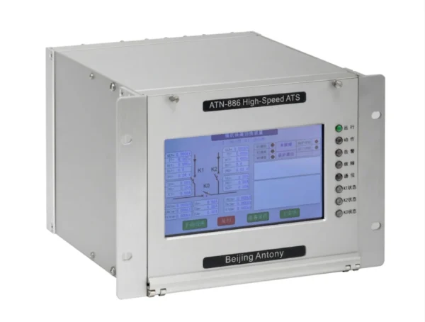
43 Automatic Transfer Switch (ATS) / High-Speed ATS
This microcomputer fast switching device, also known as High-Speed ATS and Automatic Transfer Switch, is newly developed on our latest embedded hardware and software platform, serving as a multifunctional ATS product tailored for metallurgy, petrochemical and other industrial scenarios.
ANSI:43/43T/43B
Communication Mode
Optional: RS-485, CAN bus, Ethernet, IEC 60870-5-103 (IEC-103), IEC 61850
Send your requirements, we will quote for you within 12 hours
Description
What is Automatic Transfer Switch
- This microcomputer fast switching device, also known as High-Speed ATS and Automatic Transfer Switch, is newly developed on our latest embedded hardware and software platform, serving as a multifunctional ATS product tailored for metallurgy, petrochemical and other industrial scenarios.
- Safety: During switching, it tracks the voltage, frequency and phase of power sources on both sides of the circuit breaker in real time. Equipped with multiple reliable startup and switching modes, it realizes rapid and safe standby power supply switching without severe impact on motors.
- Flexibility: Conventional devices are custom-built for specific wiring and operating modes, requiring complicated modifications when working conditions or wiring schemes change. This device adapts to diverse on-site operating scenarios, and only partial parameter setting adjustments are needed to fit various engineering applications.
- High Speed & Precision: Adopting advanced DSP+ARM+CPLD hardware architecture and high-precision AD sampling chips, it ensures real-time data processing and rapid switching response.
- High Reliability: Dedicated anti-interference designs are applied to both hardware and software, together with comprehensive self-check and interlock logic. The device has passed top-grade third-party EMC tests, delivering outstanding anti-interference capability.
Features of the System
Full-range switching functions
- Multiple startup modes: manual, protection-initiated, undervoltage, false tripping, no-current and reverse power startup
- Parallel, series and simultaneous switching modes available
- Supports fast switching, synchronous capture switching, residual voltage switching and long-delay switching
- Complete switching interlock protection
Reliable hardware and software design
- Adopts fully enclosed back-plug structure with anti-interference design, greatly enhancing electromagnetic interference resistance.
- Equipped with interlock relay at outlet to ensure stable output action.
- Logic unit and management unit operate independently, avoiding interference to switching logic from communication and display functions.
Passed comprehensive third-party tests
- The device has attained the highest-level EMC certification, ensuring stable operation under harsh working conditions.
Communication Functions
- Supports Ethernet and RS485 interfaces, compatible with IEC60870-5-103, IEC61850 and Modbus protocols.
Powerful Fault Recording & Data Logging
- Comprehensive logs cover actions, alarms, switching status changes, self-check data, operating records and fault waveforms, enabling full operational status monitoring.
Clock Synchronization
- Equipped with software and hardware time synchronization functions.
Key Technical Specifications
Operating Environment
- Temperature: -25℃ ~ +60℃ for normal operation
- Humidity and pressure comply with DL478 standard
Mechanical Performance
- Withstands Class I severe vibration and shock response
Rated Parameters
- DC voltage: 220V, tolerance +15%, -20%
- AC voltage: 100V (line voltage), 57.74V
- AC current: 5A
- Frequency: 50Hz
Power Consumption
- AC voltage: less than 0.5VA per phase
- AC current: less than 1.0VA per phase (rated 5A); less than 0.5VA per phase (rated 1A)
- DC power: below 15W in normal operation; below 25W during tripping
Fault Recording
- Records 15 cycles before switching initiation and 235 cycles after initiation. Recording data conforms to COMTRADE99 standard.
Wiring Method of Automatic Transfer Switch
Single-mother segmentation method
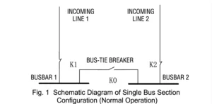
The simplified wiring diagram of single busbar sectional connection is shown in Figure 1. Incoming lines 1 and 2 can be power supply equipment such as transmission lines, main transformers and line-transformer units.
Under normal operating conditions, Bus 1 is powered by Incoming Line 1 and Bus 2 by Incoming Line 2. Switches K1 and K2 stay closed while bus tie switch K0 remains open. The device will switch over to the alternate power supply once either incoming power fails.
Single-mother household
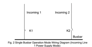
The wiring diagram of single busbar operation mode is shown in Figure 2.
In normal operation, the busbar is powered by either incoming line 1 or line 2. When powered by line 1, switch K1 closes and K2 opens, with line 2 acting as standby power supply. The device will start quickly and switch to line 2 power once line 1 power fails due to faults. The same logic applies when line 2 serves as the main power source.
List of Setting Parameters for Automatic Transfer Switches
| No. | Parameter Name | Range | Factory Default |
|---|---|---|---|
| 1 | Control Mode | Local / Remote | Local |
| 2 | Fault Switching Mode | Series / Simultaneous | Series |
| 3 | Manual Switching Mode | Parallel / Series | Series |
| 4 | K1→K2 Switch Initiation | Enable / Disable | Enable |
| 5 | K2→K1 Switch Initiation | Enable / Disable | Enable |
| 6 | K1→K0 Switch Initiation | Enable / Disable | Enable |
| 7 | K2→K0 Switch Initiation | Enable / Disable | Enable |
| 8 | K0→K1 Switch Initiation | Enable / Disable | Enable |
| 9 | K0→K2 Switch Initiation | Enable / Disable | Enable |
| 10 | Fast Switch Initiation | Enable / Disable | Enable |
| 11 | Synchronous Capture Switch Initiation | Enable / Disable | Enable |
| 12 | Residual Voltage Switch Initiation | Enable / Disable | Enable |
| 13 | Long-delay Switch Closing | Enable / Disable | Enable |
| 14 | Manual Initiation | Enable / Disable | Enable |
| 15 | Protection Initiation | Enable / Disable | Enable |
| 16 | False Tripping Initiation | Enable / Disable | Enable |
| 17 | Undervoltage Initiation | Enable / Disable | Enable |
| 18 | No-current Initiation | Enable / Disable | Enable |
| 19 | Reverse Power Initiation | Enable / Disable | Enable |
| 20 | Frequency-Voltage Initiation | Enable / Disable | Enable |
| 21 | Decoupling Protection Initiation | Enable / Disable | Enable |
| 22 | Undervoltage Incoming Line Detection | Enable / Disable | Enable |
| 23 | Directional Overcurrent Interlock | Enable / Disable | Enable |
| 24 | Output Interlock | Enable / Disable | Enable |
| 25 | PT Broken Wire Detection | Enable / Disable | Enable |
| 26 | Line Auto-recovery Function | Operation Mode Recovery / Switch Function Recovery / Disable | Disable |
FAQ
Q:What equipment is the generator automatic transfer switch mainly applied to, and what are its features?
A:
Applicable Equipment
This ATS automatic transfer switch is mainly applied to busbar, station service and standby power systems in industrial plants, and power stations.
Core Features
Instantly switch standby power to guarantee uninterrupted power supply for loads.
Multiple startup & switching modes fit various main wiring configurations.
High anti-interference performance and stable operation under harsh industrial conditions.
Comprehensive interlock protection avoids misoperation and fault spread.
Multiple startup & switching modes fit various main wiring configurations.
High anti-interference performance and stable operation under harsh industrial conditions.
Comprehensive interlock protection avoids misoperation and fault spread.
Q: What is an Auxiliary Power Fast Transfer Device?
A: It is a protection & control unit for plant auxiliary power system. When working power supply fails, it rapidly switches to standby power source within milliseconds to avoid motor stall and load power loss.
Q: What core purpose does it serve?
A: Prevent auxiliary equipment such as pumps, fans and compressors from out-of-operation due to power interruption, guarantee unit safe operation and avoid equipment damage or unit trip.
Q: What main transfer modes are supported?
A:
- Sequential transfer: Trigger switching after fault detection.
- Simultaneous transfer: Cut off faulty inlet and close standby inlet at almost the same time.
- Residual voltage transfer: Switch based on residual voltage of lost busbar.
- Manual forced transfer: On-site manual switching for maintenance.
Q: What is undisturbed transfer?
A: Switch action completes before busbar voltage and phase angle deviate excessively. Loads keep continuous power supply without obvious fluctuation, which is called undisturbed fast transfer.
Q: Where is this device commonly applied?
A: Thermal power plants, hydropower stations, nuclear power auxiliary power system, large substation station service system, chemical & metallurgy factory important dual-power busbars.
Q: How to set transfer action time?
A: Typical total switching time ≤100ms. The setting must coordinate with upstream protection to ensure transfer finishes before backup protection trips loads.
Q: Under which conditions will transfer be blocked?
A: Busbar short-circuit fault, standby power supply abnormal, PT break, overcurrent interlock signal, manual lockout status.
Q: What signals does it upload to upper system?
A: Transfer action report, fault cause, switching mode, device self-diagnosis alarm, SOE sequence of events. It supports IEC104, Modbus and other protocols to connect with SCADA.
Q: Device fails to start transfer upon power loss
A: Check voltage transformer wiring, loss-of-power logic setting, standby supply interlock condition and blocking signals.
Q: Transfer action is too slow or transfer fails
A: Verify breaker tripping/closing loop circuit, check breaker mechanical action speed and device parameter threshold.
Q: False accidental transfer without power fault
A: Eliminate PT loop interference, check wiring grounding, adjust voltage threshold and anti-jitter delay parameters.
Q: Can it record fault data?
A: Yes. It records action waveform, event sequence and switching process data for post-fault analysis.
Q: Regular maintenance items
A: Annual function simulation test; inspect secondary wiring and control loop; back up parameter configuration; check breaker linkage performance periodically.
2 reviews for 43 Automatic Transfer Switch (ATS) / High-Speed ATS
Related products
High Quality
Stable performance, reliable design, ensuring safe operation for power system protection and grid stability.
Fast Delivery
Timely delivery to support your urgent orders and project schedules efficiently and professionally at any time.
Best Warranty
Professional Warranty: Reliable after-sales support for stable relay protection and long-term customer satisfaction.
xiao zhang –
The busbar fast transfer device features ultra-fast switching speed and precise logic judgment. It rapidly completes bus load switching during working power failure to avoid equipment shutdown caused by power loss, widely used in industrial power plant and substation important load power supply guarantee.
Jack –
Harmonic restraint feature handles nonlinear loads like a charm.