
-
Leon Zhang Sales Manager
-
Email: sale@relayprotect.com
-
Phone/WhatsApp: +86 13655813266

Electromechanical Relay: Pickup, Dropout and Release Ratio
An electromechanical relay is a coil-driven switch using an electromagnet to move contacts. Learn how it works, pickup and dropout, and when to choose it.
What is an electromechanical relay and how does it work?
An electromechanical relay is a switch that moves because an electromagnet pulls it. You energise a coil, the magnetic field lifts an armature against a spring, and the contacts open or close a separate circuit. It is the oldest, most field-proven way to let a small control signal switch a large load, and it still earns its place in panels built in 2026. A 24 V DC relay with a 400 ohm coil draws 60 mA and about 1.5 W while held; at pickup, say 18 V, the armature moves, and at dropout, perhaps 6 V, it releases. Between those values the relay is bistable, because a relay that chatters between states would arc its own contacts to death. The attraction-armature type is the general-control workhorse; the induction-disk type gives the classic time-delayed protection relay. Coil and contact behaviour is specified under IEC 61810-1:2015 and IEC 60255-1:2022. Setting review and quotation within 12 hours, MOQ 1, 7-15 working days.
electromechanical relay is a switch that moves because an electromagnet pulls it. You energise a coil, the magnetic field lifts an armature against a spring, and the contacts open or close a separate circuit. It is the oldest, most field-proven way to let a small control signal switch a large load, and it still earns its place in panels built in 2026. That is the whole idea.
At a glance
- This device is a coil-driven switch: no semiconductor, no firmware, just magnetic force acting against a spring.
- Pickup is the coil value that first moves the contacts; dropout is the lower value that releases them.
- Release ratio (dropout divided by pickup) is typically 0.3 to 0.7 for a stable relay.
- IEC 60255-1:2022 and IEC 61810-1:2015 define how relays like this are built, rated and tested.
- Induction-disk units add a controlled time delay for overcurrent protection.
- They survive heat, vibration and EMI that would disable solid-state parts.
- Contacts wear out: a relay output lasts about 100,000 operations; a transistor output lasts millions.
- Use one where simplicity and fault tolerance beat speed and precision.
What Is an Electromechanical Relay, Exactly?
The short answer: it is a switch whose moving part is driven by an electromagnet rather than by a person or a motor. A coil of wire sits on an iron core. Pass current through it and the core becomes a magnet; the magnet pulls a hinged piece of metal called the armature; the armature carries contacts that complete or break a different circuit. Everything else about the product follows from that one mechanical act.
The term gets blurred with contactors and with solid-state switches, and that is worth stating plainly. An electromechanical relay is not a sensor and not a controller. It is a decision made physical: a small current closes a path for a large one, with galvanic isolation between the two. That isolation is the reason electricians still trust it next to a 240 V motor or a 110 V DC trip coil, where a shared ground would be a hazard rather than a convenience.
How a Relay Works
Follow the sequence and the product stops being mysterious. Apply the rated voltage to the coil and current flows. That current builds a magnetic flux in the core. The flux crosses a small air gap and pulls the armature toward the core face. As the armature moves, it pushes or pulls the contact bridge, so the normally open contact closes or the normally closed contact opens. Cut the coil voltage and the flux collapses; a return spring pushes the armature back, and the contacts return to their resting state. Nothing else moves.
Selecting a relay for a live project?
Send the system voltage, CT ratio and tripping scheme. Our engineers confirm the model and reply within 12 hours.
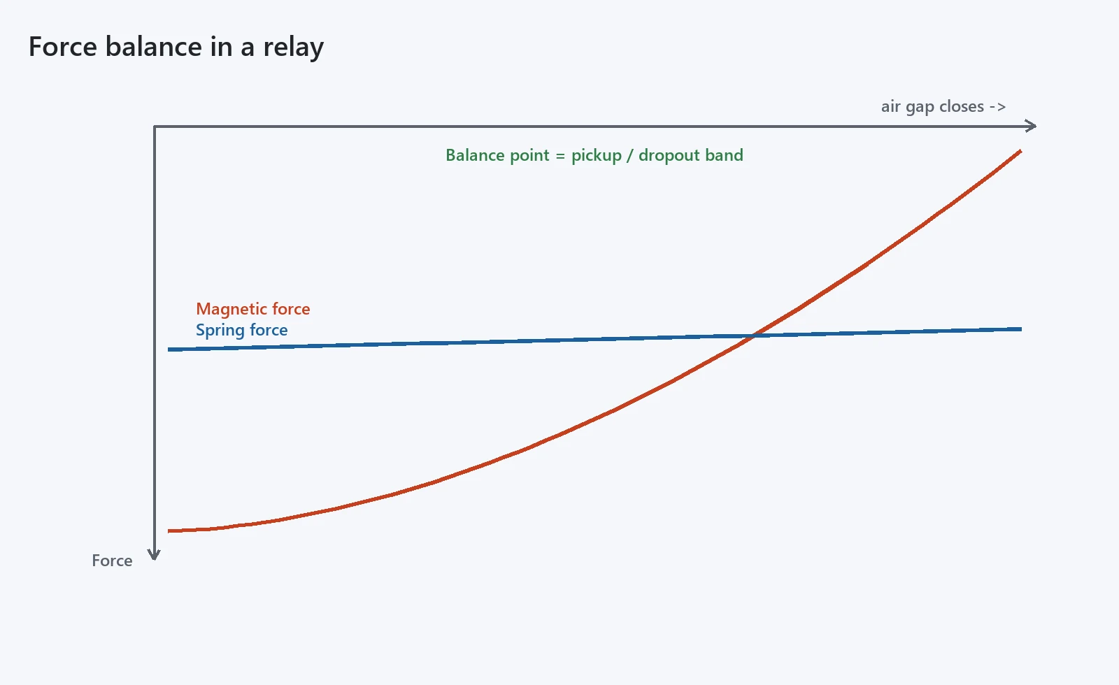
Two details decide whether the relay is any good. First, the air gap is largest when the armature is open, so the coil must make enough force at the start to overcome the spring across that gap. Second, once the armature closes, the gap nearly vanishes and the same coil produces far more force than needed, which is why a relay snaps rather than drifts. That snap is what gives it clean, mostly bounce-free switching, and why a relay is predictable to fault-find in the field.
Consider a concrete example. A 24 V DC relay with a 400 ohm coil draws 60 mA and about 1.5 W while held. At pickup, say 18 V, the armature moves; at dropout, perhaps 6 V, it releases. Between those values the relay is bistable in practice: picked up and held, or dropped out and resting. The narrow band is deliberate, because a relay that chatters between states would arc its own contacts to death.
The Two Forces You Are Really Balancing
Relay vs Solid-State and Microprocessor: The Switch Decision
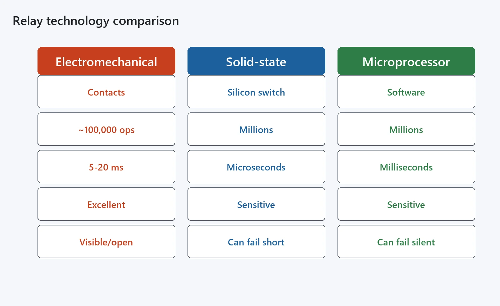
The choice between mechanical and solid-state switching is really a technology decision. A solid-state relay switches with a thyristor or MOSFET: no moving part, millions of cycles, silent. A microprocessor relay runs software on a sampled input. The mechanical relay sits at the rugged, cheap, predictable end of that range. You pick it when the environment is hostile or when a visible mechanical state is itself a safety feature, and you accept a few milliseconds of delay and a finite contact life in return. Rugged beats clever here.
| Aspect | Electromechanical | Solid-state | Microprocessor |
|---|---|---|---|
| Switching element | Contacts moved by a coil | Silicon switch | Software on sampled data |
| Mechanical life | About 100,000 operations | Millions of cycles | Millions of cycles |
| Response time | 5 to 20 ms | Microseconds | Milliseconds, settings-dependent |
| EMI and heat tolerance | Excellent | Sensitive to heat | Sensitive to heat and noise |
| Failure mode | Visible, often open | Can fail short | Can fail silent |
| Cost at low volume | Low | Moderate | High |
None of the three is simply better. A solid-state device wins on cycles and speed but fails short-circuit in a way a contact cannot, which is why safety and trip paths still prefer a mechanical contact. A microprocessor unit adds self-test and communication but introduces firmware and a power supply that must themselves be trusted. The mechanical relay is the conservative default precisely because its failure is the one you can see.
Main Construction Types
Three families cover most of what you meet. The relay you meet most often is the attraction-armature type, with the induction-disk and moving-coil types reserved for protection and precision work. The attraction-armature type pulls a flat armature straight in and is the workhorse for general control. The induction-disk type uses a rotating magnetic field to spin an aluminium cup against a drag magnet, producing a time delay that depends on the current; this is the classic protection relay. The moving-coil type deflects a coil in a permanent field for sensitive, high-accuracy measuring relays used where a small signal must drive a precise indication.
For protection work, the induction disk is the one engineers recognise: you set a tap and a time dial, and the relay trips on overcurrent after a delay set by how far over pickup the current sits. It is slow by modern standards, but it is analogue, self-powered and impossible to confuse with a firmware bug. Many substations still carry these disks as the last line that needs no battery and no code to operate.
Pickup, Dropout and the Release Ratio
Pickup is the coil current or voltage at which the contacts first operate. Dropout is the lower value at which they release. The release ratio, dropout divided by pickup, is the number that tells you how much margin you have. A ratio near 0.3 means the relay drops out well below pickup and will not chatter; a ratio near 0.7 is sluggish and prone to hang up on noise. Most control relays land between 0.3 and 0.7, and the value is printed because it predicts behaviour under a sagging supply. Stability is the goal.
| Parameter | What it means | Typical range |
|---|---|---|
| Pickup voltage | Coil value that operates the relay | 75 to 85 percent of rated |
| Dropout voltage | Coil value that releases it | 10 to 40 percent of rated |
| Release ratio | Dropout divided by pickup | 0.3 to 0.7 |
| Contact rating | Current the contacts can break | 2 to 30 A at 250 V AC |
| Coil power | VA drawn while held | 0.3 to 5 VA |
Contact Forms: NO, NC, SPDT and Forcibly Guided
Contacts come in forms you specify by letter. Form A is normally open, closing when the relay operates. Form B is normally closed, opening when it operates. Form C is a changeover, single-pole double-throw contact that gives you both. For safety circuits you ask for forcibly guided, mechanically linked contacts so that the normally closed and normally open contacts can never be closed together, even if one welds. That detail is what separates a control relay from a safety relay, and it is written into the product standard rather than left to the panel builder. That is the difference.
| Form | Contacts | Typical use | Notes |
|---|---|---|---|
| A | Normally open | Energise to start a load | Rest state is open |
| B | Normally closed | Energise to stop a load | Rest state is closed |
| C | Changeover SPDT | Select between two paths | One moving contact |
| Forcibly guided | Mechanically linked | Safety and interlock loops | IEC 61810-3:2015 |
Timing: Instantaneous, Time-Delay and Induction-Disk
An instantaneous relay operates as soon as pickup is passed, within a few milliseconds. A time-delay relay adds a dashpot, a slow-release magnetic path or an electronic timer to hold or delay the contact. The induction-disk relay spreads its delay across the current range, which is exactly the inverse-time curve protection engineers draw by hand. Choose the timing model from the coordination study, not from habit, because the delay sets how your panel rides through a fault.
Where Electromechanical Relays Still Win
electromechanical relays keep their seat because they are honest about failure. In a generator set, a building fire panel or a railway signal, you want a device that opens visibly when it fails and keeps working through heat and vibration. A relay does that without a power supply on its output side and without firmware that can hang. For these jobs the slight delay and contact wear are a price worth paying, and the installed base is large enough that spares and skills are never scarce. That keeps them relevant.
Relays also win on isolation. The control coil and the switched contact share no conductor, so a fault on the load side cannot reach the logic side through anything but the air gap. That single property removes a whole class of failure modes that plague shared-ground semiconductor designs, and it is why a relay is still the first choice for a trip circuit that must fail de-energised.
Typical Ratings You Specify From the Datasheet
When you order an electromechanical relay, the numbers that actually matter are coil voltage and tolerance, contact rating at the real load (resistive and inductive treated separately, using the correct utilization category such as AC-15 for control or DC-13 for solenoid duty from IEC 60947-5-1), dielectric strength across the open contact, and mechanical plus electrical life. Do not size the contact to the motor nameplate; size it to the locked-rotor or inrush current, because that is what welds a contact shut. A relay rated 10 A at 250 V AC resistive may only manage 1 A at the same voltage when switching an inductive coil. Size for the worst case.
The Electromechanical Relay Switch Selection Checklist
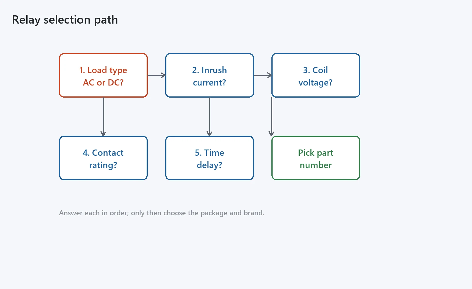
Before you write a part number, answer these in order. What is the load, AC or DC, and what is its inrush? What coil voltage do you have, and is it DC or AC? Does the contact need to be forcibly guided for a safety loop? Do you need a time delay? Only after those do you pick the package and the brand. Skipping the load question is the usual reason a relay burns out in a month, because the printed contact rating assumes a clean resistive load that the field rarely provides. Start with the load.
Wiring and Panel Layout Notes
Mount the relay where the coil lead runs away from the contact lead, because a relay is also a small transformer and can induce noise across its own terminals. Use surge suppression on the coil if you drive it from a transistor, and keep the contact wiring short and separated from analogue signals. A tidy panel is not cosmetics; it is what keeps the device from picking up on stray fields, and it is what lets the next person fault-find it in the dark. Tidy panels pay off.
Coordination With Protection and Controls
In a substation or a machine panel, the relay rarely stands alone. It sits between the protection intelligence and the device it switches, or it forms the trip path itself in an older panel. Coordinate its dropout with the protection time dial and with the control power ride-through, or it will drop out on a voltage sag the protection was designed to ride through. Treat the relay as a link in the chain, not a component in isolation, and the whole panel becomes easier to defend. Specify the pair together.
A worked example makes the coordination point concrete. Suppose a panel runs on a 125 V DC control bus that can sag to 90 V during a fault. If pickup is 85 percent of 125 V, that is about 106 V; the bus at 90 V is then below pickup, so the relay drops out exactly when the bus sags. If the protection is meant to ride through that sag, the relay dropout must be set lower, or you add a capacitor across the coil to bridge the dip. The relay and the protection have to be specified together, not bought separately and hoped to agree.
Maintenance, Testing and Failure Modes
The failure you watch for is contact weld, where an arc fuses the contacts shut, and the slower drift of pickup as the spring relaxes or the core rusts. A bench test measures pickup, dropout and contact resistance; a thermal scan catches a coil running hot. Plan to replace relays on a life count, not on failure, in any circuit where a stuck contact is expensive or dangerous, because by the time a weld shows up it has already failed its one job. Replace on a count.
There is also the slow failure that is harder to see: the contact that still closes but at rising resistance, so the load sees a voltage drop and heats up. Logging contact resistance at service intervals turns that silent drift into a scheduled swap. It is unglamorous work, but it is the difference between a panel that surprises you and one that ages on a known curve.
Standards That Govern the Product
The documents that matter when you specify or accept an electromechanical relay are IEC 60255-1:2022 for measuring relays and protection equipment, IEC 61810-1:2015 for electromechanical elementary relays, IEC 61810-2:2017 for reliability, IEC 61810-3:2015 for forcibly guided contacts, and IEC 61812-1:2023 for time relays. A datasheet that quotes these is one you can defend to an inspector, and a panel that lists them is one you can maintain for twenty years. Quote them by number.
| Standard | Scope | Edition |
|---|---|---|
| IEC 60255-1 | Measuring relays and protection equipment | 2022 |
| IEC 61810-1 | Electromechanical elementary relays | 2015 |
| IEC 61810-2 | Reliability | 2017 |
| IEC 61810-3 | Forcibly guided contacts | 2015 |
| IEC 61812-1 | Time relays | 2023 |
When a Relay Is the Wrong Choice
The electromechanical relay is the right part in most panels, but not all. Reach for something else when any of these hold.
- You need millions of silent cycles a year: a solid-state or transistor output will outlast the relay by orders of magnitude.
- The load is a high-frequency or PWM signal: contact bounce and arcing will destroy the relay in days.
- You need sub-millisecond, repeatable timing: only a microprocessor relay holds that accuracy.
- The contact must switch a current well above its rating: derate hard or pick a contactor instead.
Conclusion
An electromechanical relay is a cyclic, coil-driven switch with galvanic isolation and a visible mechanical state, and it remains the default choice where ruggedness and predictability beat speed. Specify it from pickup, dropout, contact rating and the real load inrush, cite IEC 60255-1:2022 and IEC 61810-1:2015, and it will still be working when the firmware around it has been rewritten twice.
Related reading
- Our Power Relay: Types, Ratings, Selection Guide and Applications covers the heavier switching side.
- The Transfer Switch for Generator guide shows the trip path in practice.
- The PLC guide explains the logic that drives these coils.
- For panel data, our PLC Programming and Line Protection and Control Panel pages go deeper.
Frequently asked questions
Engineers ask the following questions most when they specify or replace a relay on a panel.
What is the difference between an electromechanical relay and a contactor?
Both are coil-driven switches, but a contactor is built for heavy continuous motor and heater loads, often with arc chutes and overload relays, while a relay is sized for control and signal switching. A contactor usually handles tens to hundreds of amps; a relay handles milliamps to a few amps.
How does a relay work step by step?
You apply voltage to the coil, current creates a magnetic field, the field pulls a hinged armature toward the core, the armature moves the contacts, and the contacts open or close a separate circuit. Remove the coil voltage and a spring returns the armature, so the contacts go back to their resting state.
What do pickup and dropout mean on a relay?
Pickup is the coil current or voltage at which the contacts first change state. Dropout is the lower value at which they return. The ratio of dropout to pickup, typically 0.3 to 0.7, tells you how stable the relay is against supply ripple and noise.
Are electromechanical relays still used today?
Yes. They still sit in protection panels, building controls, generator sets and railway signalling because they tolerate heat, vibration and electromagnetic interference that disables semiconductors, and they fail in a visible, predictable way rather than silently.
Relay vs solid state: which should I choose?
Choose a relay when you need isolation, tolerance to harsh environments and a clear mechanical state. Choose a solid-state relay when you need millions of silent switching cycles, fast response and no contact wear. The switch decision comes down to lifespan versus ruggedness.
What standards apply to relays?
IEC 60255-1:2022 covers measuring relays and protection equipment, IEC 61810-1:2015 covers electromechanical elementary relays, IEC 61810-2:2017 covers reliability, IEC 61810-3:2015 covers forcibly guided contacts, and IEC 61812-1:2023 covers time relays.
How long do relay contacts last?
A relay output is rated for roughly 100,000 mechanical operations at full load, while a transistor output lasts millions. Actual life drops sharply if you switch inductive loads or currents above the rated value, so derate the contact for the real load.
What is a forcibly guided contact relay?
It is a relay whose normally closed and normally open contacts are mechanically linked so that they cannot be closed at the same time, even if the contacts weld. IEC 61810-3:2015 defines this, and it is required in safety circuits where a stuck contact must never fake a safe state.
Related guides: DCS control system · HMI system · Switch board
Related: Alternating relays
Send the nameplate data if you want the settings checked before the panel is built.
About Author

Hello, I'm Leon Zhang. I have 15 years of experience in the power relay protection industry with extensive pre-sales and after-sales project experience. Our company specializes in various complete sets of relay protection and automation equipment. I can assist customers in solving all practical on-site project challenges and provide optimal integrated solutions.
Tell Us Your Requirement



High Quality
Stable performance, reliable design, ensuring safe operation for power system protection and grid stability.
Fast Delivery
Timely delivery to support your urgent orders and project schedules efficiently and professionally at any time.
Best Warranty
Professional Warranty: Reliable after-sales support for stable relay protection and long-term customer satisfaction.