
-
Leon Zhang Sales Manager
-
Email: sale@relayprotect.com
-
Phone/WhatsApp: +86 13655813266
Contactors vs Relays: Utilization Categories and Selection
Contactors switch motor and heating loads that would weld a relay shut. See how IEC 60947-4-1:2023 utilization categories, coil duty and sizing set the rating.
How do you select a contactor versus a relay?
Contactors are electrically operated switching devices built to make and break power circuits again and again, rated for load currents above roughly 9 A and for motor starting duty that would weld an ordinary relay shut. IEC 60947-4-1:2023 defines the utilization categories behind every rating, and IEC 60947-1:2020 sets the general rules. A 22 kW pump drawing 42 A starts several times an hour; a lighting bank switches twice a day but carries 60 A; a capacitor bank steps in and out as the power factor controller calls for it. All three use the same device family, but each stresses the contacts differently. What separates a contactor from a relay is arc chutes, contact springs sized for inrush and a frame absorbing the shock of closing at six times rated current. Buy on duty first, then current: a unit rated 3,600 operations an hour differs from one switching a heater once a shift. Setting review and quotation within 12 hours, MOQ 1, 7-15 working days.
Contactors are electrically operated switching devices built to make and break power circuits again and again, rated for load currents above roughly 9 A and for motor starting duty that would weld an ordinary relay shut. IEC 60947-4-1:2023 defines the utilization categories behind every current rating on the datasheet, and IEC 60947-1:2020 sets the general rules.
At a glance
- IEC 60947-4-1:2023 sets the utilization categories that decide every current rating on a contactor datasheet.
- A frame rated 25 A at AC-1 commonly drops to 9 A at AC-3, the category covering squirrel-cage motors.
- Motor inrush reaches six times full-load current, which is why main contacts close with a wiping action under arc chutes.
- A contactor relay switches control and signalling circuits and is rated for thermal current, not for load duty.
- Coil inrush runs three to ten times the sealed holding current, which is why DC coils get economiser circuits.
- Mechanical endurance on small frames reaches 10 million operations; electrical endurance under AC-3 sits closer to 1 million.
- A DC arc has no current zero, so a DC contactor relies on magnetic blowouts to stretch and cool it.
- A contactor does not clear short circuits. The fuse or breaker ahead of it does that work.
What Contactors Are Built to Do
Contactors earn their place where a load has to be switched often, under load, and without anyone standing next to it. A 22 kW pump drawing 42 A at 400 V starts several times an hour. A warehouse lighting bank switches twice a day but carries 60 A. A capacitor bank steps in and out as the power factor controller calls for it. All three jobs go to the same family of device, and each one stresses the contacts differently.
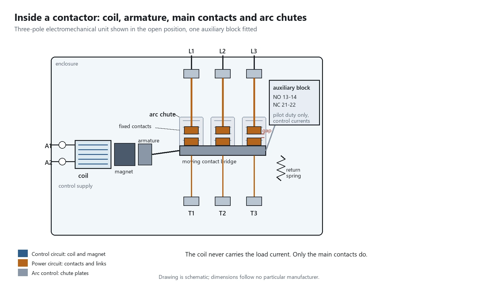
The mechanism inside is simple. A coil pulls an armature, the armature closes contacts, and the contacts carry the load current. A spring opens everything again when the coil drops out.
What separates a contactor from a general-purpose relay is everything built around that mechanism: arc chutes, contact springs sized for inrush, and a frame that absorbs the shock of closing at six times rated current.
Frequency of operation is the real specification.
A contactor rated for 3,600 operations an hour on a jogging conveyor is a different machine from one that switches a heater once a shift, even when both carry the same nameplate current. Buy on duty first, then check the current. Buying on current alone is how frames end up undersized for the work they actually do.
Selecting a relay for a live project?
Send the system voltage, CT ratio and tripping scheme. Our engineers confirm the model and reply within 12 hours.
Inside Contactors: Coil, Contacts and Arc Control
Four assemblies decide the service life of an electromechanical contactor, and two of them are mechanical rather than electrical.
The electromagnet is a laminated core with a shading ring on AC designs. Without the ring the armature would chatter at every current zero, which is why a 50 Hz coil hums when the ring cracks. Coil consumption splits into two numbers: the inrush needed to close and the sealed value needed to hold.
Main contacts are silver alloys, usually silver tin oxide, and they close with a wiping action that cleans the surface as it goes. Double-break contacts put two gaps in series, which doubles the voltage the same travel can interrupt.
Arc chutes are the part people forget.
When contacts open under load the current does not simply stop. It ionises the air in the gap and keeps flowing as an arc. The chute is a stack of steel plates that splits, stretches and cools that arc until the voltage across it exceeds what the supply can sustain.
Auxiliary contact blocks clip onto the front or side of the frame. They are rated for pilot duty, not for load, and they exist to tell the rest of the panel what the contactor did.
| Assembly | What it does | Failure signature | Reference |
|---|---|---|---|
| Electromagnet and coil | Pulls the armature in and holds it with reduced current | Armature chatter, open circuit coil, burnt shading ring | IEC 60947-4-1:2023 |
| Main contacts | Carry load current, wipe closed, break under arc | Welding, pitting, erosion toward end of life | IEC 60947-4-1:2023 |
| Arc chute | Splits and cools the arc at opening | Cracked plates, tracking to the frame | IEC 60947-4-1:2023 |
| Auxiliary contacts | Report contactor state to the control circuit | High resistance on pilot circuits, failed interlock | IEC 60947-5-1:2024 |
| Springs and enclosure | Return the armature, insulate live parts | Spring fatigue, cracked housing, slow drop-out | IEC 60947-1:2020 |
Table 1. Four assemblies and the measurement that catches each one before it stops the plant.
How Contactors Make and Break a Motor Circuit
Closing takes more out of the device than opening does, which surprises most people. At the instant a direct-on-line motor starts, the contacts must make roughly six times full-load current at a power factor near 0.35. Once the motor is up to speed they carry rated current, and when the contactor opens it breaks only that running current.
So an AC-3 contactor is tested to make 6 × Ie and break 1 × Ie.
Reversing duty breaks that pattern. When a contactor plugs a running motor, or jogs it in short bursts, it opens while the current is still at starting level. Now it must break 6 × Ie as well as make it, and the electrical endurance of the same frame drops by roughly an order of magnitude.
Watch the changeover gap.
A reversing pair needs electrical interlocking between the two devices, and mechanical interlocking where a welded contact is possible. If both ever close together the supply is shorted across two phases, and no setting on the overload relay will save the contacts.
Utilization Categories: Why One Frame Carries Three Ratings
A contactor is sold with one thermal current and several operational currents, and the operational currents differ by a factor of three on the same frame.
Nothing here is marketing. The utilization category encodes the load: whether it is resistive, whether the device closes against inrush, and whether it also opens against inrush.

| Category | Load | Make | Break | Typical use |
|---|---|---|---|---|
| AC-1 | Resistive, cos φ at or above 0.95 | 1 × Ie | 1 × Ie | Heaters, distribution feeders |
| AC-3 | Squirrel-cage motor, start and stop while running | 6 × Ie | 1 × Ie | Pumps, fans, compressors |
| AC-4 | Squirrel-cage motor, plugging and jogging | 6 × Ie | 6 × Ie | Cranes, hoists, machine tools |
| AC-6b | Capacitor bank switching | Up to 30 × In | 1 × In | Power factor correction steps |
| DC-1 | Resistive DC load | 1 × Ie | 1 × Ie | Heating, DC distribution |
| DC-3 | Shunt motor starting, plugging, jogging | 4 × Ie | 4 × Ie | DC drives, traction auxiliaries |
Table 2. Utilization categories on a contactor datasheet, with the current each one demands.
A worked example makes the point. Take a 22 kW, 400 V motor with a full-load current of 42 A. Under AC-3 the contactor needs Ie of at least 42 A at 400 V, so a 50 A frame is the normal choice. Put the same motor on a conveyor that reverses every 30 s and the duty becomes AC-4, where the same frame might carry only 18 A. The frame goes up two sizes, not because the current changed, but because the switching did.
AC-3e appears on newer datasheets for motors with higher locked-rotor current. Where a manufacturer publishes it, use it.
Do not read the AC-1 figure off the same line and size a motor from it.
Contactor vs Relay: What Actually Differs
The question comes up on every panel build, and the honest answer is that the two devices overlap. A contactor is a relay in the sense that it is an electrically operated switch. What separates them is what each one is rated to do repeatedly.
| Attribute | Contactor | Control relay |
|---|---|---|
| Rated current | 9 A to several thousand amperes | Up to about 10 A on general-purpose types |
| Contact arrangement | Main contacts, normally open, three-pole | Changeover, multi-pole, mixed NO and NC |
| Arc suppression | Arc chutes, magnetic blowouts on DC | Minimal, relies on a small gap and fast break |
| Switching duty | Frequent, thousands of operations an hour | Intermittent, signalling duty |
| Governing standard | IEC 60947-4-1:2023 | IEC 61810-1:2015 |
| Role in a panel | Carries the load | Decides and reports |
Table 3. Where a contactor and a control relay part company.
Overlap exists at the edges. A 25 A relay with a proper arc chute is a contactor in all but name, and a small contactor pressed into signalling duty will run for years. The useful test is what the contacts have to interrupt.
Ask what the contacts open into. That question settles most of the argument.
What a Contactor Relay Is
A contactor relay is a device in its own right, not a comparison. IEC 60947-5-1:2024 covers electromechanical control circuit devices, and the contactor relay is the member of that family built with contactor-style construction: a coil, an armature and several contacts rated for control circuits rather than power.
The contacts carry pilot duty. Typical figures are 10 A thermal current with AC-15 or DC-13 ratings for switching solenoid valves, indicator lamps and PLC inputs. Where an ordinary control relay offers two or four changeover contacts, a contactor relay offers four to eight.
Latching versions matter on two jobs.
They hold a circuit closed through a control power failure, and they let a PLC keep a state without energising a coil for hours. A mechanically held contactor does the same thing at power currents, and it is the one to specify when the load itself has to stay on.
Relay vs Contactor: Choosing for the Circuit in Front of You
Work from the load backwards.
Write down the steady current, the inrush multiple, the supply type and how many times an hour the device has to switch. If the list includes motor starting current, the job needs a contactor. If it includes only coil and indicator currents, a relay will do it at a fraction of the cost and panel depth.
Protection changes the picture too. A motor protection relay sits alongside the contactor and trips it through the coil circuit when the thermal model says the motor is in trouble. The relay decides and the contactor acts. ANSI C37.2 device numbers cover both roles, and mixing them up on a drawing is a common source of confusion.
Two devices, two jobs. Keep both on the drawing.
Sizing Contactors from Motor Full-Load Current
Contactors are sized from the motor nameplate, not from the frame size of whatever starter survived the last shutdown.
Take the full-load current at the actual operating voltage, pick the utilization category that matches the duty, and read Ie at that category and that voltage. A 22 kW, 400 V motor with a full-load current of 42 A needs Ie of 42 A or more at AC-3. Most catalogues list motor power against frame size, but the power table assumes a standard motor, and a high-efficiency machine can draw more at start.
Then check the short-circuit side.
The contactor does not clear faults. IEC 60947-4-1:2023 requires coordination with the short-circuit protective device ahead of it, and the two coordination types describe what you accept afterwards: Type 1 allows damage that must be repaired before restart, Type 2 allows only light welding that separates on opening.
Type 2 costs more. On a line where stopping is expensive, it is usually worth it.
Coil Voltage, Inrush and Suppression
Coil voltage is a separate decision from load voltage. A contactor switching 400 V motors can carry a 24 V DC coil, a 230 V AC coil, or a wide-range electronic coil that accepts both.
Pick-up happens at about 0.85 times rated control voltage, and drop-out lands somewhere between 0.2 and 0.7 depending on the design. That wide drop-out band is why a contactor can ride through a brownout and then drop everything at once when the voltage recovers slowly.
Inrush is three to ten times the sealed current.
On a DC coil a small economiser circuit, or a pulse-width modulated electronic coil, cuts holding power by 80 to 90 percent. In a panel with forty of them standing closed all shift, that difference shows up in the control transformer sizing.
Suppression protects whatever drives the coil. A varistor across an AC coil, or a diode with a zener across a DC coil, clamps the inductive kick that would otherwise land on the PLC output. A DC coil without a suppressor will destroy a transistor output within a season.
AC and DC Duty: Why DC Is the Harder Switching Job
An AC arc passes through a current zero twice a cycle, and at that zero it extinguishes almost by itself. A DC arc never sees a zero. Once the contacts part, the arc has to be stretched until the voltage across it exceeds the supply voltage, and that takes length.
Hence magnetic blowouts on DC designs: a coil or a permanent magnet drives the arc into the chute instead of letting it sit on the contact face. A frame with a blowout can break roughly twice the current of the same frame without one.
Derate hard on DC. A frame rated 25 A at AC-3 may hold 25 A at DC-1 and only a fraction of that at DC-3 or DC-5, where the load is a motor with inrush.
Auxiliary Contacts and Interlocks
An auxiliary contact is not a spare main contact. It is a pilot device mounted on the same armature, rated for control currents, and the panel depends on it for two jobs.
The first is the holding circuit. A start pushbutton energises the coil, an auxiliary contact in parallel with that button keeps the coil alive after the operator lets go, and the stop button, the overload relay contact and any safety interlock sit in series with the coil. Lose the auxiliary contact and the motor runs only while the button is held.

The second job is interlocking. In a reversing starter each contactor carries a normally closed auxiliary contact in the other one’s coil circuit, so both cannot pick up together. Electrical interlocking alone is not enough where a welded contact is possible; mechanical interlocking between the two armatures is the second line of defence.
Where the Contactor Sits in a Motor Starter
A direct-on-line starter is three devices in series, and confusion about which one does what causes most mis-specification.
The circuit breaker or fuse ahead of the contactor clears short circuits. The contactor switches the load as often as the process demands. The overload relay measures current and opens the coil circuit when the motor has run too hot for too long.
The overload relay does not open the power circuit. It opens the coil circuit, and the contactor opens the power circuit.

Soft starters and variable speed drives take over the starting duty and keep a bypass contactor for running, which is why the AC-3 rating still appears on those drawings too.
How Contactors Fail and What to Measure
Contactors announce their decline long before they stop working, and the signs are mostly mechanical.
Contact weld is the failure everyone fears, and it comes from making or breaking more current than the category allows. A frame closing into a stalled motor at six times rated current, repeatedly, welds. So does a frame sized from AC-1 figures and pressed into AC-4 duty.
Chatter is the second signature. A cracked shading ring, a coil running below pick-up voltage, or enough voltage drop in the control wiring to sag the coil during inrush will all make the armature buzz. Chatter is not a nuisance. Each buzz is another make-and-break cycle at full current.
Coil burnout follows sustained overvoltage or a plunger that never seats, because a coil draws far more current with the air gap open than closed.
Contact erosion is the slow one. Material transfers across the arc on every operation, and the end-of-life criterion in the standard is loss of a defined fraction of contact mass, not a visible pit.
| Signature | Likely cause | What to measure |
|---|---|---|
| Armature buzz or hum | Cracked shading ring, low coil voltage | Coil voltage at the terminals during inrush |
| Contacts stuck closed | Welding from over-duty or a short circuit | Contact resistance, spring return |
| Slow or failed drop-out | Residual magnetism, worn spring, sticky grease | Drop-out time after the coil is de-energised |
| Coil hot to touch | Overvoltage, plunger not seating | Sealed current against the datasheet |
| Pitting and material transfer | Normal erosion reaching end of life | Contact mass loss against the maker criterion |
Table 4. Failure signatures and the reading that separates a real fault from normal wear.
When a Contactor Is the Wrong Choice
Five situations come up often enough to list.
- Where the circuit has to be isolated for work. A contactor has no visible break, and welded contacts leave the load live with the coil dead. Put a switch-disconnector ahead of it.
- Where fault current has to be cleared. A contactor has no short-circuit breaking capacity of its own, and coordination with a fuse or breaker is mandatory.
- Where the duty is rare and the current is small. A 9 A heater on a timer is relay territory, and a contactor adds cost, coil heat and panel depth for nothing.
- Where the load is DC at inductive voltages. A frame rated only for AC-3 will not survive DC-3 duty even at half the current.
- Where the process jogs or plugs continuously. AC-4 duty needs an AC-4 frame, and the permitted operating frequency in the catalogue has to be checked, not just the current.
Numbers to Put on the Enquiry
A complete enquiry saves a round of catalogue emails.
- Rated operational voltage Ue and frequency.
- Utilization category, with the actual duty named: AC-3, AC-4, AC-6b or DC-3.
- Rated operational current Ie at that category and voltage, never the AC-1 figure alone.
- Coil voltage and type, AC or DC, with a wide-range coil where the control supply is uncertain.
- Number and rating of auxiliary contacts, normally open and normally closed.
- Coordination type with the short-circuit device, Type 1 or Type 2, and the fuse or breaker it was tested with.
Standards and Sources
Every figure above traces back to one of the editions below. Check the edition date before quoting a number on a drawing.
| Standard | What it covers | Edition |
|---|---|---|
| IEC 60947-4-1:2023 | Utilization categories and ratings for electromechanical switching and motor-starting duty | 5th edition, 2023 |
| IEC 60947-1:2020 | General rules for low-voltage switchgear and controlgear | 6th edition, 2020 |
| IEC 60947-5-1:2024 | Control circuit devices and switching elements, contactor relays | 5th edition, 2024 |
| IEC 61095:2023 | Switching devices for household and similar purposes | 2023 |
| IEC 61810-1:2015 | Electromechanical elementary relays | 2015 |
| IEC 60947-6-2:2020 | Control and protective switching devices (CPS) | 3rd edition, 2020 |
Table 5. Standards behind the figures above.
Frequently Asked Questions
What is the difference between a contactor and a relay?
A contactor switches load current and is rated to do it thousands of times an hour, with arc control built in. A control relay switches signals and small pilot loads. Overlap exists between about 10 A and 25 A, where the deciding factor is what the contacts have to interrupt.
Why does one contactor carry three different current ratings?
Because the utilization category changes with the load. The same frame might be rated 25 A at AC-1 for resistive heating, 9 A at AC-3 for motor starting, and 6 A at AC-4 for plugging and jogging. Always read Ie at the category that matches your duty.
Can a contactor be used as an isolator?
No. A contactor has no visible break, and its contacts can weld closed, leaving the load live with the coil de-energised. Isolation for maintenance needs a switch-disconnector or a disconnector ahead of the contactor.
How do I size a contactor for a three-phase motor?
Take the motor full-load current at the operating voltage, choose the utilization category for the duty, and select a contactor whose Ie at that category and voltage is not less than the full-load current. Check the coil voltage separately.
Does a contactor protect the motor against overload?
The contactor itself does not. The overload relay measures current and opens the coil circuit when the motor has run too hot for too long. The contactor then opens the power circuit. Short circuits are cleared by the fuse or breaker ahead of it.
Can a contactor interrupt a short circuit?
No. A contactor has no rated short-circuit breaking capacity. IEC 60947-4-1:2023 requires coordination with a short-circuit protective device, and Type 1 or Type 2 coordination describes how much contact damage you accept afterwards.
What causes a contactor to chatter?
Low coil voltage, a cracked shading ring on an AC coil, excessive voltage drop in the control wiring during inrush, or a plunger that never seats. Chatter matters because each buzz is another make-and-break cycle at full load current.
Conclusion: Where This Leaves You
Contactors are a duty specification dressed up as a current rating. Name the category first, then the current, then the coil, and most of the failure modes above stop appearing on the maintenance list.
Read the datasheet in that order.
The panel gets quieter, and the spare-parts shelf gets smaller.
Related Reading
- Power relay ratings and coil types
- How a control relay is defined and classified
- The circuit breaker that clears faults ahead of the contactor
- ANSI C37.2 device numbers on standards.ieee.org
Related guides: Annunciator · Generator interlock · Electromechanical relay
If the selection has to be checked against your switchboard, send the single-line and the ratings.
Where a contactor is replaced by a protected switching device: low voltage motor protection relay; ASD-441H motor protection relay; smart switchgear controller.
About Author

Hello, I'm Leon Zhang. I have 15 years of experience in the power relay protection industry with extensive pre-sales and after-sales project experience. Our company specializes in various complete sets of relay protection and automation equipment. I can assist customers in solving all practical on-site project challenges and provide optimal integrated solutions.
Tell Us Your Requirement



High Quality
Stable performance, reliable design, ensuring safe operation for power system protection and grid stability.
Fast Delivery
Timely delivery to support your urgent orders and project schedules efficiently and professionally at any time.
Best Warranty
Professional Warranty: Reliable after-sales support for stable relay protection and long-term customer satisfaction.