

-
Leon Zhang sales consultant
-
Email: zxl635973785@gmail.com
-
Phone/WhatsApp: +86 13655813266
Supply Case of Low-Voltage PV Reverse Power Protection Equipment in Sri Lanka | Solution for Self-Consumption PV Projects
Low-voltage PV reverse power protection is the ANSI 32 scheme that stops a self-consumption photovoltaic plant from exporting surplus power into the public grid, and this page documents the 400 V supply case delivered to a renewable energy EPC contractor in Sri Lanka.
Low-Voltage PV Reverse Power Protection at a Glance
- What it blocks: surplus active power leaving the PV plant at the point of common coupling, not the generation itself.
- Function: ANSI 32 directional power on the LV incomer, with under-power as a second stage.
- Rated point: 400 V three-phase, 50 Hz, matching Sri Lankan low-voltage distribution practice.
- Pickup basis: a value above the export that appears at the site minimum load, so a normal day never trips the incomer.
- Delay basis: longer than the inverter own anti-islanding window, otherwise the two functions fight each other.
- Actuator: the PV incoming breaker. The load feeder is not taken out of service.
- Recovery: the relay recloses the PV incoming breaker once reverse power falls below pickup for the reset delay.
- Evidence: an event record carrying power, direction, voltage, frequency and time stamp for the utility inspection.
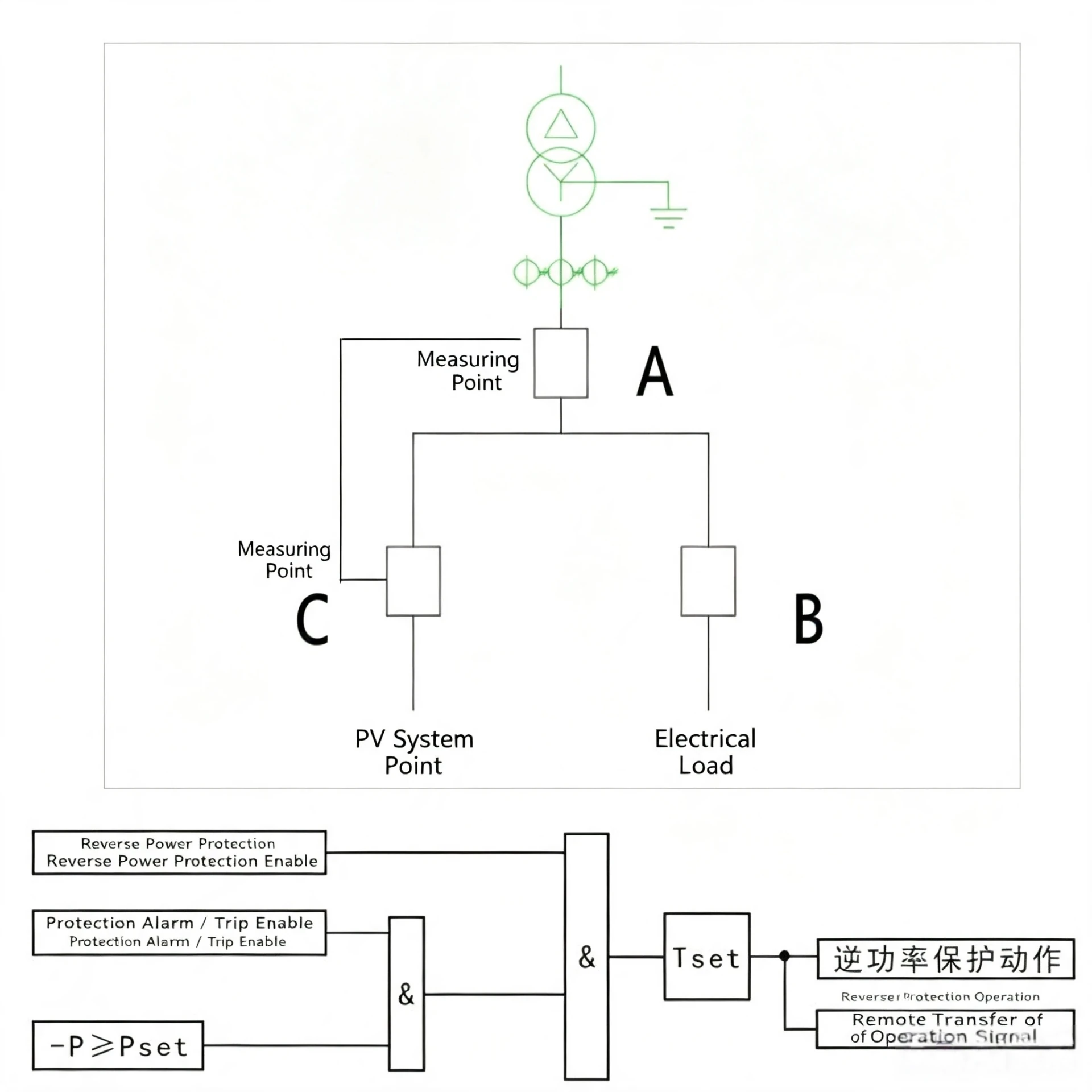
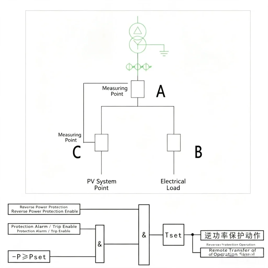
A PV reverse power relay decides which way the energy is moving. An overcurrent relay only counts amperes, so it cannot tell a fault current from the export that follows a cloud edge. Directional power compares the flow against the reference voltage and trips only when it turns from the network towards the plant.
Standards Behind the Sri Lanka PV Case
The device is built as an IEC 60255 measuring and protecting relay, with IEC 61850 or Modbus carrying the records to the site SCADA. Anti-islanding is a separate duty and does not cover this one. IEC 62116 and IEEE 1547 fix what the inverter must do when the grid disappears, while solar anti-reverse power is what the incomer relay does while the grid is still there and the plant still exports.
The two duties sit on the same incomer, so one setting sheet has to name which function reaches the breaker first. During the commissioning of this project the answer was documented in the commissioning record, not left to the site engineer. The principle behind directional power is set out in the reverse power flow protection guide.
What This Case Covers
The sections below follow the order a contractor actually works in: the site constraint and the capacity scope, the selection and quotation path, the scheme and its settings, the device and its wiring, then production, packaging, remote commissioning and acceptance, and finally the related reading and the conclusion.
Project Overview
This is a project case of low-voltage PV reverse power protection on a 400 V commercial incomer. The client operates several self-consumption photovoltaic plants on rooftops and car parks, and the local utility forbids export at the point of common coupling.
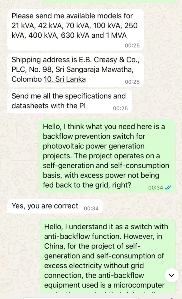
The supply covers 21 kVA up to 1 MVA of plant capacity, from technical verification and quotation to production, sea freight, remote commissioning and site acceptance.
Twenty-one kilovolt amperes to one megavolt ampere is the whole range this scheme covers.
Company Profile
Shipping protection equipment into a foreign grid is mostly paperwork and dates. The certificate set has to be in the language the utility reads, the datasheet has to match the interconnection document, and the delivery date has to fit the commissioning plan the contractor has already committed to. Missing any one of the three turns a delivery into a storage charge.
The relay family used on this project sits in the renewable energy relay protection range, which is selected by voltage class, function list and communication protocol rather than by catalogue number.
Project Background & Technical Requirements
Client Requirements
The client operates several commercial and industrial self-consumption photovoltaic projects. The local grid code forbids export, so the incomer needs a dedicated reverse power function that reads the power flow in real time and trips the PV incoming breaker before any energy reaches the utility network.
Zero export at the coupling point is the acceptance criterion, not a target. Solar anti-islanding protection covers the opposite case, when the grid is gone and the plant must disconnect, and the two functions share the same incomer.
Applicable PV Capacity Scope
The scope spans the distributed capacities that appear on commercial and industrial roofs in Sri Lanka, from a small 21 kVA car park array up to a 1 MVA industrial roof. The same five functions cover the whole range:
- Real-time monitoring of grid-connected active/reactive power, voltage and frequency;
- High-precision power flow detection to avoid reverse power injection into public grid;
- Supports reverse power protection and under-power protection; trips PV incoming switch once abnormal power flow is detected;
- Automatic reclosure of PV incoming switch after operating conditions recover;
- Built-in data logging and fault alarm for routine operation and maintenance inspection.
Inquiry Handling, Technical & Commercial Communication Process
Every inquiry runs the same path. Capacity and load profile come first, the datasheet package second, and the quotation third, because a quotation written before the load profile is a quotation that gets reissued.
Step 1: Product Screening & Submission of English Documentation
Based on the client’s PV capacity, self-consumption operation mode and local grid connection requirements, we select low-voltage PV reverse power protection equipment with stable performance, complete certifications and competitive cost. A full set of English technical datasheets, product manuals, certificates and parameter comparison documents are compiled and submitted to the client’s engineering team for preliminary evaluation.
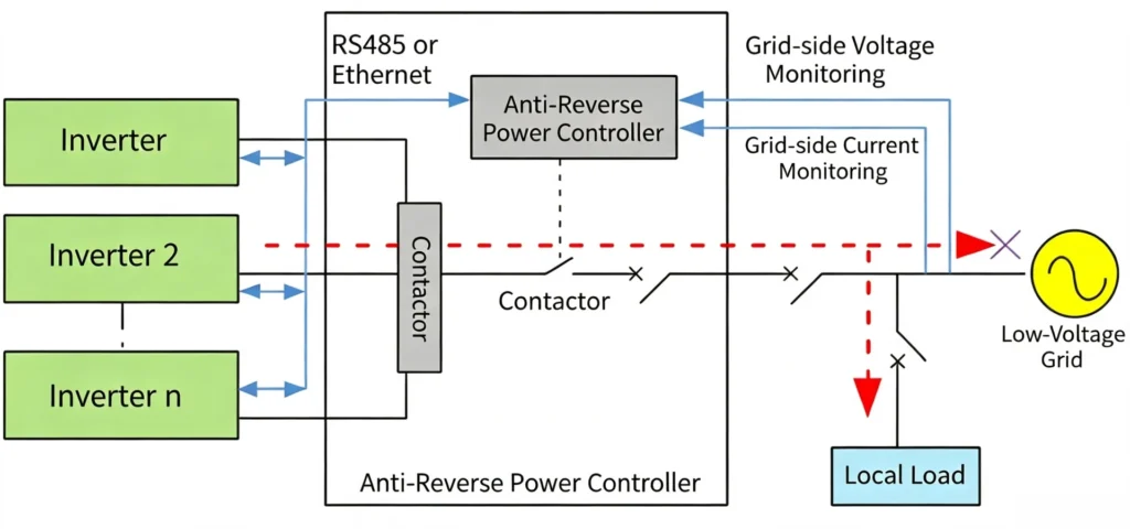
Two schemes exist for anti-reverse power. The first trips the incoming breaker once reverse or under power is detected. The second holds the inverter back and curtails its output until the export disappears. Both meet the grid code on paper, but they need different things from the site.
The trip type was used on this project because the site had no spare inverter headroom to curtail and no local team able to change inverter limits later.
Step 2: In-depth Technical Communication & Parameter Confirmation
One session with the site engineers fixed the four numbers that matter: the rated voltage, the accuracy class, the response time and the protocol on the communication port. Sampling is 400 V phase to phase at 50 Hz on the low-voltage side. The relay reads the same voltage and frequency band that the utility meter on the incomer uses.
The control logic is fixed by the client specification, so verification was a list, not an opinion. Each item on the specification was ticked against the relay menu, the wiring was routed through the client drawings, and the whole run was repeated over a remote video session so the client engineers could see the same menu they will use later.
Step 3: Formal Standard Quotation
After confirming the technical proposal, we issue formal international quotations with clear and complete terms, covering core concerns of overseas buyers:
| Quotation Item | Standard Terms |
|---|---|
| Product Certification | CE, ISO 9001, compliant with IEC 61850 and IEC 62116 PV grid connection standards |
| MOQ | Small trial orders and bulk supply supported to meet tender requirements |
| Lead Time | Fixed production schedule for overseas orders to guarantee on-time delivery |
| Payment Terms | Flexible and secure international trade payment options |
| Warranty | Official long-term warranty + lifelong technical consultation service |
Reverse Power Scheme and Relay Settings for a 400 V PV Incomer
Why a Self-Consumption Plant Still Exports
Self-consumption only works if the load runs at the same time as the array. A commercial roof does that on a weekday afternoon and misses it completely at Saturday lunchtime, when the building is empty and the plant is at full output. The export is not an error. It is the normal result of two curves that do not match.
Shading makes it worse. One blocked string on a morning pushes its whole block into the grid while the rest of the roof is still producing, so a plant with a self-consumption meter, a generation meter and an export meter can look correct on the display and still trip the incomer.
Three meters can disagree. The relay only sees the incomer.
ANSI 32 Setting Basis
Three numbers carry the whole function. Direction comes from the voltage reference, so the relay needs a live voltage from the incomer PT or from the three phase voltage input. Pickup is set in kilowatts, above the export that the site produces at minimum load and below the export that the site expects at midday.
A reverse power protection case study only means something if the numbers are written down, so the pickup and the delay used here are the ones that went on the project setting sheet.
The delay separates the relay from the inverter. The inverter anti-islanding function is faster, and the utility meter is faster still, so the reverse power stage has to be slower than both or it will act on a transient that nobody else sees.
Pickup is in kilowatts. Delay is in seconds. Both are written on the setting sheet before the relay is ordered.
CT and PT ratio follow the incomer, not the array. The relay measures what crosses the coupling point, so a ratio taken from the array side will read the export the wrong way round.
A wrong ratio reads the export backwards.
Trip Logic and Recovery
The trip output goes to the PV incoming breaker. The load feeder is untouched, which is why a reverse power trip on this scheme stops the export and nothing else.
Reclosing is automatic but not instant. The reset delay has to outlast a cloud edge, otherwise the breaker opens again the moment the array comes back and the incomer cycles for the whole afternoon.
Each trip is written to the event log with power, direction, voltage and time. That record is what the utility asks for during the inspection, and what the client reads when the export meter disagrees.
The log ends the argument.
Low-Voltage PV Reverse Power Protection Equipment Introduction
The mismatch between array output and site load is the whole problem. A roof array produces most of its energy between nine and four, and a commercial building is often quiet at the weekend, which is exactly when export appears. This device closes the gap at the incomer.
Core Functions
- Real-time Power Monitoring: Continuously collect grid-connected power, voltage, current and frequency with high precision to dynamically identify power flow direction;
- Trip-type Anti-Reverse Power Control: Relay trips upon detection of surplus power to achieve zero power back-feed to public grid. The relay closes to restore power supply of PV incoming circuit after reverse power disappears;
- Integrated Grid Fault Protection: Combines overvoltage, undervoltage, overfrequency, underfrequency and overload protection to guarantee safe grid connection of PV systems;
- Fault Logging & Alarm: Automatically store operation data and fault records, supporting remote access and on-site fault analysis.
Installation & Wiring Features
- Installation Options: Embedded mounting available; DIN rail mounting is optional upon project request, compatible with conventional low-voltage switchgears for Sri Lankan PV projects;
- Simple Wiring: Independent terminals for power supply, signal sampling and communication with clear marking to reduce wiring errors;
- Strong Environmental Adaptability: Wide operating temperature and humidity range, suitable for hot and humid tropical climate in Sri Lanka;
- Convenient Commissioning: Preloaded standard anti-reverse power parameters, supporting one-click parameter modification according to project operating conditions.
Standardized Overseas Production & Quality Control
Humidity and salt air are the two reasons a protection device fails early in Sri Lanka. Every unit in this order went through a test written for the climate it would ship into, not for the climate of the factory floor.
The line runs component screening, high and low temperature ageing, power precision calibration, an interference test and one simulated grid connection per unit. Each unit is then checked against the capacity parameters of the project it is going to, because a relay set for a 100 kW array behaves differently on a 1 MVA incomer.
Professional Export Packaging & Ocean Freight
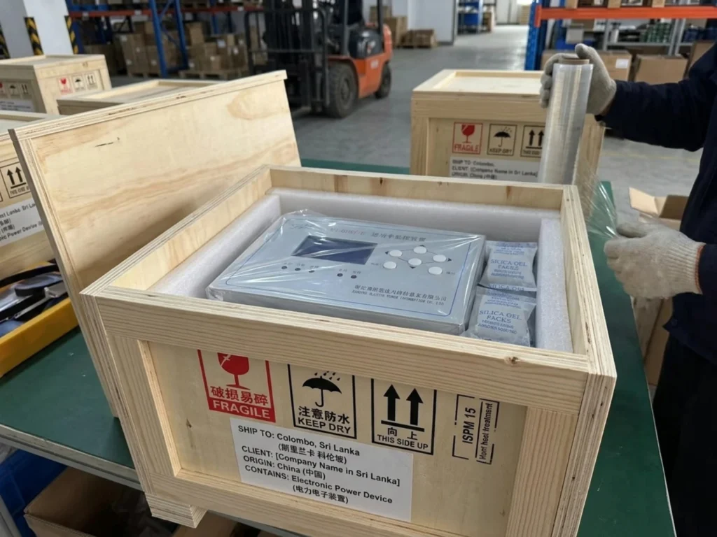
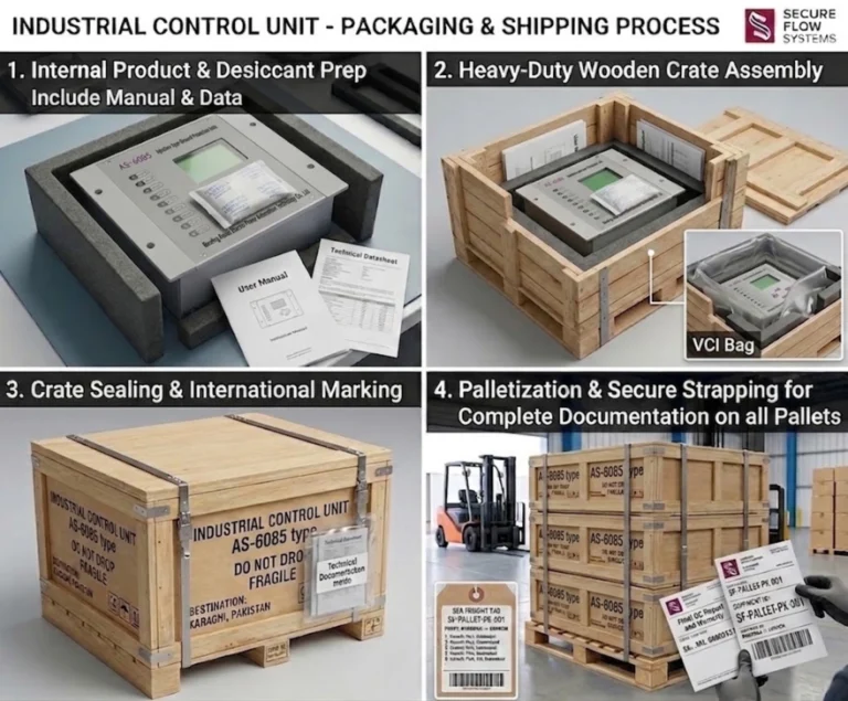
Taking long-distance sea transportation and tropical humid environment of Sri Lanka into consideration, all equipment adopts export-grade moisture-proof, waterproof and shockproof packaging:
- Fully wrapped by waterproof & moisture-proof film to avoid damp damage during sea transit;
- Fixed with internal shockproof foam to prevent vibration and collision damage during transportation;
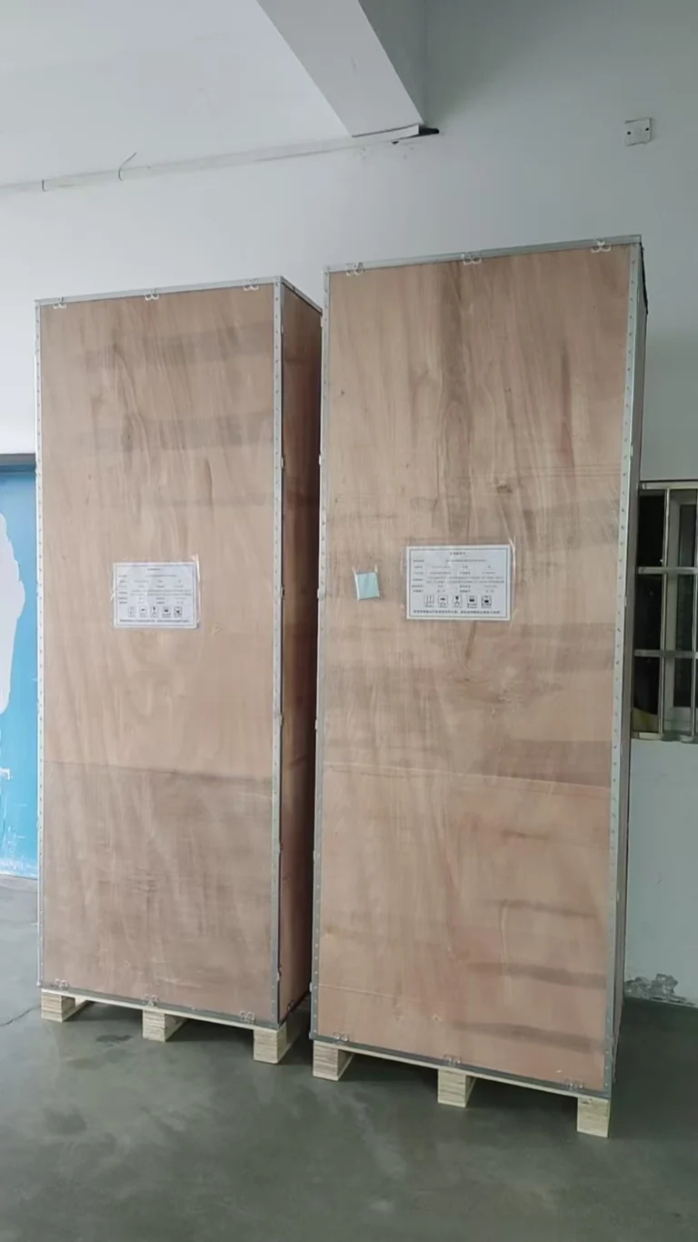
- Hard carton outer package reinforced with strapping belts to resist extrusion inside containers. We adopt standard container sea transport, complete formal export customs declaration and document filing, and provide full set of shipping documents and certification papers to ensure smooth customs clearance and intact delivery to project sites in Sri Lanka.
Remote Installation Guidance, Commissioning & Project Acceptance
After goods arrive on site, our professional new energy technical team provides free one-stop remote after-sales support for the Sri Lankan client.
The site team was walked through installation, wiring check, parameter load and the reverse power logic test in one session. Commissioning then ran the plant through a full irradiance range, from a cloudy morning to a full sun afternoon, and the export was recorded at each step.
One session, four steps, one menu.
Acceptance meant the utility inspection and the trial run, both signed off against the design indicators. What the record shows is the number the client cares about: export at the coupling point, measured over a full day of generation.
Frequently Asked Questions (FAQ)
What reverse power value should the relay pick up?
Set the pickup above the export the site produces at minimum load and below the export it produces at midday. For a 400 V commercial incomer that usually lands between two and five per cent of the inverter rating, but the only correct number is the one taken from the site load curve.
Does ANSI 32 replace solar anti-reverse power or anti-islanding protection?
Neither one replaces the other. ANSI 32 acts while the grid is live and the plant is exporting. Anti-islanding acts when the grid disappears. Both are fitted on the same incomer, and the setting sheet has to say which one reaches the breaker first.
Can the reverse power relay work if the grid voltage fails?
Not as a measuring function. Directional power needs a voltage reference, so a lost voltage makes the relay lose its direction judgement. On this scheme the anti-islanding stage and the under voltage stage cover that condition and take the incomer out.
What standards apply to a 400 V PV incomer?
IEC 62116 and IEEE 1547 set the inverter interconnection duty, IEC 60255 covers the measuring and protecting relay, and IEC 61850 or IEC 60870-5-103 covers the path to the SCADA. The local grid code decides the numbers that go on top of those.
How is the reverse power function tested on site?
Secondary injection supplies a current and voltage to the relay inputs with the direction reversed, and the pickup and delay are read off the relay display. A plant with a known export is then run up during the day to confirm the incomer holds, which is the test the utility wants to see in the commissioning record.
Why did this project use the trip type instead of inverter curtailment?
Curtailment needs spare inverter headroom and a site team able to change the inverter limits later. This client had neither, so the breaker trip on the incomer was the only scheme that could be commissioned and handed over.
Related Reading
- Reverse power flow protection explains the direction judgement behind ANSI 32.
- Solar anti-islanding protection covers the case where the grid is already gone.
- ANSI 32 reverse power protection relay lists the model variants and their terminal wiring.
- Electrical protection for solar power substations takes the same functions up to the medium voltage incomer.
Conclusion
Low-voltage PV reverse power protection comes down to three numbers and one output. The pickup and the delay decide when the relay acts; the output decides what it opens. Everything else on the device, from the event log to the communication report, exists to prove those three numbers were set correctly.
The scheme used in Sri Lanka trips the PV incoming breaker on directional power, holds the load feeder, and recloses once the export falls below pickup for the reset delay. That behaviour passed the utility inspection and is what the commissioning record shows.
On a 400 V incomer the practical form of low-voltage PV reverse power protection is one directional power stage, one output to the breaker and one reset delay that outlasts a cloud edge.
For a contractor the order of work is fixed: take the day load curve, write the pickup and delay on the setting sheet, fit the relay on the incomer board, then test it with secondary injection before the plant is switched on.
low-voltage PV reverse power protection devices are supplied on a standing basis across the whole 21 kVA to 1 MVA range, for EPC contractors, project owners and engineering teams working in Sri Lanka and the rest of South Asia.
Three inputs, one function list.
The configuration follows three inputs: the plant capacity, the grid code of the country and the wiring already present in the incomer board. CE and ISO 9001 documentation ships with the order, which is what the tender file asks for.
Send the plant capacity, the day load curve and the incomer wiring diagram. Those three items are enough to return a function list, a pickup range and the settings sheet for the reverse power stage.
About Author

Hello, I'm Leno Zhang. I have 15 years of experience in the power relay protection industry with extensive pre-sales and after-sales project experience. Our company specializes in various complete sets of relay protection and automation equipment. I can assist customers in solving all practical on-site project challenges and provide optimal integrated solutions.
Tell Us Your Requirement
High Quality
Stable performance, reliable design, ensuring safe operation for power system protection and grid stability.
Fast Delivery
Timely delivery to support your urgent orders and project schedules efficiently and professionally at any time.
Best Warranty
Professional Warranty: Reliable after-sales support for stable relay protection and long-term customer satisfaction.