

-
Leon Zhang sales consultant
-
Email: zxl635973785@gmail.com
-
Phone/WhatsApp: +86 13655813266
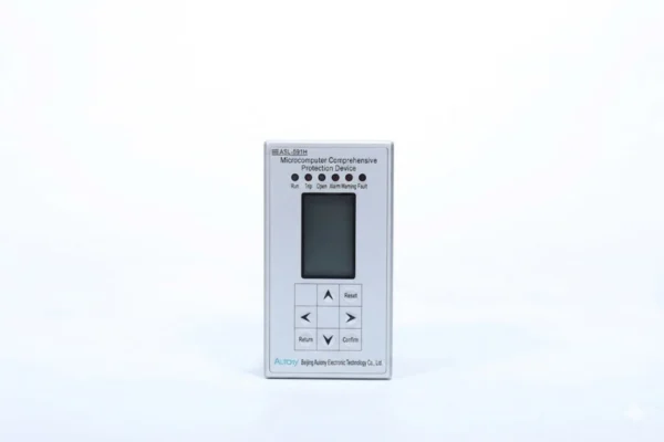
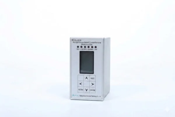
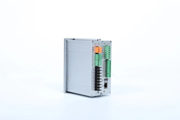
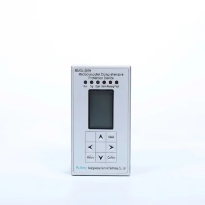
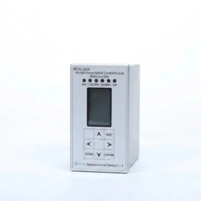
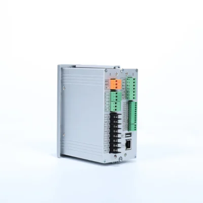
Digital Multifunction Protective Relay ASL-591H
Overview of Digital Multifunction Protective Relay
The ASL-591H digital multifunction protective relay protects 10kV and below RMU/GIS lines and 380V distribution room lines.
ANSI
50/51/49/51N/63
Communication Mode:Optional: RS-485, CAN bus, Ethernet, IEC 60870-5-103 (IEC-103)
Send your requirements, we will quote for you within 12 hours
Description
Overview of Digital Multifunction Protective Relay
- The ASL-591H Microprocessor-Based Comprehensive Protection Device, a digital multifunction protective relay, is suitable for the comprehensive protection of 10 kV and below incoming and outgoing lines in ring main units and gas-insulated switchgear, as well as 380 V low-voltage incoming and outgoing lines in distribution rooms.
Features of Numerical Protection Relay
- This multifunction protection relay is suitable for plant service transformers, power supply feeders and bus tie protection at 10 kV and below. It supports AC/DC 220 V and DC 110 V power supplies (24 V/48 V available on request). Featuring a compact design, it is easy for instrument room installation.
Functions of Digital Multifunction Protection Relays
- Two-stage overcurrent protection (instantaneous current tripping & definite-time overcurrent), each stage can be independently enabled or disabled;
- Overload protection: output configurable for tripping or alarm;
- Zero-sequence overcurrent protection: output configurable for tripping or alarm;
- Inverse-time overcurrent protection: fixed output for tripping;
- Non-electrical protection: heavy gas tripping (transformer door interlock), over-temperature tripping, light gas alarm, over-temperature alarm, etc.
Event Logging Function of Digital Multifunction Protection Relay
- The log records events including protection trip events, alarm events, and device self-test failures;
- It records the type and time of protection trip events, as well as the type and time of device self-test failures.
Numerical Protective Relays – Communication Functions
- Upload real-time data, including measurement data, fault alarm signals, and protection settings.
- Receive control commands from higher-level systems.
Communication Interface
- This device provides a high-speed, reliable RS-485 interface for external communication. It supports the standard MODBUS protocol.
Rated DC Specifications
- Voltage: 220 V, 110 V;
DC voltage ripple factor: ≤2%; voltage fluctuation: 80–115% of rated voltage
Rated AC Specifications
- Rated AC current In: 5 A, 1 A;
- The AC power waveform is sinusoidal, with a distortion factor not exceeding 2%;
- Frequency fn: 50 Hz (60 Hz option available; specify when ordering), with a tolerance of ±0.5%.
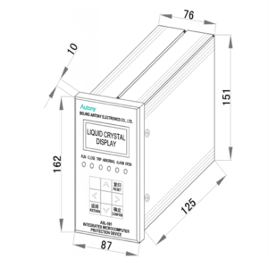
Dimensions of Numerical Protection Relays
Multifunctional Protection Relay Setting Sheet
| No. | Name | Range | Step | Remarks |
|---|---|---|---|---|
| 1 | Stage 1 Protection Setting (Instantaneous Current Trip) | |||
| 1.1 | Stage 1 Protection Enable | 1/0 | — | Stage 1 protection: Enable(1) / Disable(0) |
| 1.2 | Stage 1 Time Delay | 0~120.00s | 0.01s | |
| 1.3 | Stage 1 Setting Value | 0.40~99.99A | 0.01A | |
| 2 | Stage 2 Protection Setting (Definite-time Overcurrent) | |||
| 2.1 | Stage 2 Protection Enable | 1/0 | — | Stage 2 protection: Enable(1) / Disable(0) |
| 2.2 | Stage 2 Time Delay | 0~120.00s | 0.01s | |
| 2.3 | Stage 2 Setting Value | 0.40~99.99A | 0.01A | |
| 3 | Overload Setting | |||
| 3.1 | Overload Protection Enable | 1/0 | — | Overload protection: Enable(1) / Disable(0) |
| 3.2 | Overload Trip Mode | 1/0 | — | Overload: Trip(1) / Alarm(0) |
| 3.3 | Overload Time T | 0~120.00s | 0.01s | |
| 3.4 | Overload Current I | 0.40~99.99A | 0.01A | |
| 4 | Zero-sequence Overcurrent Setting | |||
| 4.1 | Zero-sequence Overcurrent Enable | 1/0 | — | Zero-sequence overcurrent protection: Enable(1) / Disable(0) |
| 4.2 | Zero-sequence Overcurrent Trip Mode | 1/0 | — | Zero-sequence overcurrent: Trip(1) / Alarm(0) |
| 4.3 | Zero-sequence Time Delay | 0~120.00s | 0.01s | |
| 4.4 | Zero-sequence Setting Value | 0.5~99.99A | 0.01A | |
| 5 | Inverse-time Overcurrent Setting | |||
| 5.1 | Inverse-time Overcurrent Enable | 1/0 | — | Inverse-time overcurrent protection: Enable(1) / Disable(0) |
| 5.2 | Inverse-time Time Constant T | 0.1~120.00s | 0.01s | Time constant of inverse-time overcurrent protection |
| 5.3 | Inverse-time Current Setting I | 1~10A | 0.01A | Setting value of inverse-time overcurrent protection |
| 6 | Non-electrical Protection Setting | |||
| 6.1 | Non-electrical Protection 1 Enable | 1/0 | — | Non-electrical protection 1: Enable(1) / Disable(0) |
| 6.2 | Non-electrical Protection 1 Trip Mode | 1/0 | — | Non-electrical protection 1: Trip(1) / Alarm(0) |
| 6.3 | Non-electrical Protection 2 Enable | 1/0 | — | Non-electrical protection 2: Enable(1) / Disable(0) |
| 6.4 | Non-electrical Protection 2 Trip Mode | 1/0 | — | Non-electrical protection 2: Trip(1) / Alarm(0) |
| 6.5 | Non-electrical Protection 3 Enable | 1/0 | — | Non-electrical protection 3: Enable(1) / Disable(0) |
| 6.6 | Non-electrical Protection 3 Trip Mode | 1/0 | — | Non-electrical protection 3: Trip(1) / Alarm(0) |
| 6.7 | Non-electrical Protection 4 Enable | 1/0 | — | Non-electrical protection 4: Enable(1) / Disable(0) |
| 6.8 | Non-electrical Protection 4 Trip Mode | 1/0 | — | Non-electrical protection 4: Trip(1) / Alarm(0) |
| 6.9 | Non-electrical 1 Time Delay | 0.1~120.00s | 0.01s | |
| 6.10 | Non-electrical 2 Time Delay | 0.1~120.00s | 0.01s | |
| 6.11 | Non-electrical 3 Time Delay | 0.1~120.00s | 0.01s | |
| 6.12 | Non-electrical 4 Time Delay | 0.1~120.00s | 0.01s | |
| 6.13 | Non-electrical Parameter Value | 0000~FFFF | — | |
| 7 | General Setting | |||
| 7.1 | Three-element Wiring Enable | 1/0 | — | Three-element wiring: Enable(1) / Disable(0) |
| 7.2 | Current Transformation Ratio | 0~9999 | 1 |
FAQ
Q:How are comprehensive protection relays typically installed and used, and what types of equipment can they protect?
A:Compact comprehensive protection devices are suitable for installation in ring main units and high-voltage switchgear. With control in numerical protection relay integrated, they provide complete protection for feeders, feeder terminals, distribution transformers and small motors.
Q What is this relay?
A microprocessor-based IED integrating protection, measurement, control, fault recording and communication, replacing multiple discrete electromagnetic relays for power system protection.
Q Core advantages vs traditional relays
All-in-one compact design, high precision settings, built-in fault waveform recording, remote communication, continuous self-diagnosis and no mechanical drift.
Q Common built-in protection elements
50/51 overcurrent, 50N/51N earth fault, 67 directional overcurrent, 27/59 undervoltage/overvoltage, 46 negative sequence, 32 reverse power, 87 differential, 81 frequency protection, breaker failure & trip circuit supervision.
Q Typical application objects
10/35kV feeders, distribution transformers, medium-voltage motors, capacitor banks, bus tie & incoming cabinet auto transfer logic.
Q Required input signals
Three-phase CT current, three-phase PT voltage, zero-sequence current; digital inputs for breaker status & interlock signals, digital outputs for trip, close and alarm.
Q Built-in circuit monitoring
Supports PT fuse failure and CT broken wire detection, automatically alarms and blocks relevant protection to prevent false tripping.
Q Ways to configure parameters
Local panel operation, PC software via USB/485, or remote download through SCADA system.
Q Protection coordination principle
Adopt definite/inverse time curves with time & current grading to ensure selective tripping between upstream and downstream equipment.
Q Supported protocols
Modbus, IEC 103/104, DNP3, IEC 61850 with GOOSE for smart substation interlocking.
Q Key data recording
Real-time electrical measurements, event logs, fault oscillography and action records for post-fault analysis.
Q False tripping main causes
CT polarity/ratio error, PT abnormality, over-sensitive settings, electromagnetic interference or unremoved blocking signals.
Q Protection fails to trip
Loss of control power, CT secondary open/short circuit, excessively high pickup values, broken trip circuit or external interlock locking.
Q Self-check alarm
Hardware failure of power supply, mainboard or memory; replace the unit or send for factory repair.
Q Necessary commissioning items
CT/PT polarity check, secondary injection test, DI/DO loop verification, communication debugging and setting file backup.
Q Routine maintenance
Monthly status check; annual terminal tightening and dust cleaning; full function inspection during major overhaul every 4~6 years.
Q Optional extra features
Auto-reclosing, cold load pickup, password permission lock for parameter modification, IEC 61850 GOOSE peer-to-peer intertrip.
Q Usage value
Reduces cabinet space, wiring workload and fault points, widely adopted in new distribution substations and industrial power distribution systems.
2 reviews for Digital Multifunction Protective Relay ASL-591H
Related products
High Quality
Stable performance, reliable design, ensuring safe operation for power system protection and grid stability.
Fast Delivery
Timely delivery to support your urgent orders and project schedules efficiently and professionally at any time.
Best Warranty
Professional Warranty: Reliable after-sales support for stable relay protection and long-term customer satisfaction.
xiao zhang –
All‑in‑one distribution relay cuts costs by replacing separate relays. Precise measurement, flexible logic and standard communication suit global substations & factories, perfect for exports.
Jack –
Works well in harsh electrical environments — very robust.