

-
Leon Zhang sales consultant
-
Email: zxl635973785@gmail.com
-
Phone/WhatsApp: +86 13655813266
How to Select a Transformer Protection Relay: A Practical Guide for Engineers
Introduction
Transformer protection relay selection is not a one‑size‑fits‑all task. A small distribution transformer needs a simpler scheme than a large power transformer.
Selecting the wrong relay or missing a critical protection function can cause transformer damage, unnecessary outages, or failure to clear internal faults. The decision depends on transformer rating, voltage level, winding connection, grounding method, and fault current.
This guide helps engineers and EPC teams select the right transformer protection relay based on actual system requirements, not generic recommendations.
This guide explains how to select a transformer protection relay based on the transformer’s electrical characteristics, protection requirements and system application.
What Is a Transformer Protection Relay?
A transformer protection relay monitors transformer electrical and thermal conditions. It trips the circuit breaker when it detects abnormal conditions.
What Does a Transformer Protection Relay Protect Against?
Key fault types include:
- Phase-to-phase and phase-to-ground faults
- Winding faults
- Overload and overheating
- Internal faults (gas accumulation)
- External faults that stress the transformer
Why Is Transformer Relay Selection Important?
Good protection detects faults quickly and limits transformer damage. It avoids unnecessary trips that shut down loads. Selectivity ensures only the faulty transformer or section is isolated. Backup protection covers primary protection failures.
What Factors Should You Consider When Selecting a Transformer Protection Relay?
Engineers evaluate these factors before choosing a relay.
| Selection Factor | What to Check |
|---|---|
| Transformer rating | kVA / MVA |
| Voltage level | Primary and secondary voltage |
| Transformer type | Distribution, power, or generator step‑up |
| Winding configuration | Wye, delta, or zig‑zag |
| Grounding method | Solid, resistance, impedance, or isolated |
| Short‑circuit level | Maximum and minimum fault current |
| Transformer impedance | %Z |
| CT ratio | Primary and secondary CT ratings |
| Protection requirements | Differential, OC, EF, REF, etc. |
| Cooling method | ONAN, ONAF, OFAF, etc. |
| Temperature monitoring | Winding and oil temperature |
| System configuration | Radial, ring, parallel, grid‑connected |
| Communication | IEC 61850, Modbus, DNP3, etc. |
| Installation | Indoor, outdoor, panel, or switchgear |
Step 1 — Determine the Transformer Rating and Voltage Level
Start with nameplate data. This defines the relay’s measurement range and CT requirements.
Check Transformer Capacity
Transformer capacity is rated in kVA or MVA. Use this formula for full‑load current:
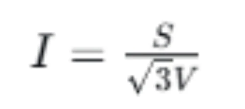
Where:
- S = transformer rating (kVA or MVA)
- V = line‑to‑line voltage (kV)
Full‑load current determines CT ratio and overcurrent pickup settings. Consider emergency loading and overload capability if specified.
Check Primary and Secondary Voltage
Common transformer voltage combinations include:
- 11/0.4 kV (distribution)
- 22/0.4 kV (distribution)
- 33/11 kV (sub‑transmission)
- 110/33 kV (transmission)
- 220/110 kV (high‑voltage transmission)
Higher voltage and larger capacity transformers typically require more comprehensive protection schemes, including differential protection.
Step 2 — Identify the Transformer Type and Application
Different transformer applications have different protection priorities.
Distribution Transformer Protection
Distribution transformers typically serve residential or light industrial loads. Protection often includes overcurrent, earth fault, overload, and temperature protection. Surge protection may also be required.
Power Transformer Protection
Power transformers are larger and more critical. Protection includes differential (87T), restricted earth fault (REF), overcurrent, earth fault, thermal, and Buchholz protection.
Generator Step‑Up Transformer Protection
These transformers connect generators to the transmission system. Protection includes transformer differential, combined generator‑transformer differential, earth fault, overexcitation, and backup overcurrent protection.
Auxiliary and Industrial Transformers
Protection depends on transformer size, load type, and system criticality. Smaller auxiliary transformers may use overcurrent and earth fault only. Critical industrial transformers often add differential and thermal protection.
Step 3 — Determine Which Transformer Protection Functions Are Required
This table shows common ANSI protection functions for transformers. Select functions based on transformer size, voltage, and application.
| ANSI Function | Protection | Typical Purpose |
|---|---|---|
| 87T | Transformer differential | Internal phase faults |
| 50/51 | Overcurrent | Phase fault / backup protection |
| 50N/51N | Earth fault | Ground faults |
| 64REF / 87N | Restricted earth fault | Sensitive internal ground faults |
| 49 | Thermal protection | Overheating protection |
| 24 | Overexcitation | V/Hz protection |
| 63 | Gas/Buchholz | Internal transformer faults |
| 26 | Thermal device | Temperature monitoring |
| 50BF | Breaker failure | Backup protection |
| 46 | Negative sequence | Unbalanced conditions |
| 27/59 | Under/overvoltage | Voltage protection |
Step 4 — Decide Whether Transformer Differential Protection Is Required
Differential protection (87T) is one of the most important decisions in transformer relay selection.
When Is 87T Differential Protection Recommended?
- Power transformers above 10 MVA
- Critical transformers where internal faults must be cleared quickly
- High‑voltage transformers (66 kV and above)
- Generator step‑up transformers
When May Overcurrent Protection Be Sufficient?
- Smaller distribution transformers (below 5 MVA)
- Non‑critical installations
- Simple radial distribution systems
What Does a Transformer Differential Relay Protect?
A differential relay compares currents entering and leaving the transformer. Any difference indicates an internal fault. It protects winding phase faults and some ground faults, but requires CT matching and vector group compensation.
Step 5 — Consider Transformer Earth Fault Protection
Earth fault protection depends on the transformer grounding method and neutral connection.
Conventional Earth Fault Protection
Standard earth fault elements (50N/51N) detect ground faults on the transformer or connected feeders. They are suitable for solidly grounded or resistance‑grounded systems.
Restricted Earth Fault Protection
REF (64REF or 87N) provides sensitive protection for internal ground faults on grounded transformer windings. It covers a limited zone, usually the transformer winding and the bushing CTs. REF is more sensitive than conventional earth fault protection and is often used on large transformers.
How Does the Grounding Method Affect Relay Selection?
The neutral grounding method directly affects earth fault current magnitude. Solid grounding produces high fault currents, easily detected by standard elements. Resistance grounding reduces fault current, requiring sensitive elements or REF.
Step 6 — Check CT Requirements for Transformer Relay Selection
CT performance is critical for accurate transformer protection. Mistakes here cause field issues.
Select the Correct CT Ratio
The CT primary rating must exceed the transformer full‑load current on each side. The secondary rating (1 A or 5 A) must match the relay input.
Check CT Accuracy and Saturation
Protection CTs are typically Class 10P or 5P. Verify the CT does not saturate at maximum fault current. Saturation distorts secondary current and can delay operation.
Check CT Connection and Polarity
For differential protection, CT polarity and connection must be correct. Incorrect polarity causes false differential current during normal operation.
Consider Transformer Vector Group
The transformer vector group defines phase displacement between primary and secondary windings. Common groups include Dyn11, YNd1, YNd11, and Yy0. The relay must compensate for this phase shift in differential protection settings.
Step 7 — Consider Transformer Inrush Current
Inrush current is often overlooked in relay selection but causes frequent nuisance trips.
Why Does Transformer Inrush Current Matter?
When a transformer energizes, it draws a high magnetizing current, up to 8–12 times full‑load current. This current decays over several cycles but can exceed overcurrent pickup settings.
How Can Inrush Current Cause Nuisance Tripping?
If the relay responds to inrush as a fault, it trips the transformer before it can energize. This happens when using instantaneous overcurrent elements without harmonic restraint.
Harmonic Restraint and Differential Protection
Modern differential relays use second‑harmonic restraint to distinguish inrush from fault current. This feature prevents false tripping during energization. Verify your selected relay includes this capability for transformers with differential protection.
Step 8 — Consider Overexcitation and V/Hz Protection
Overexcitation occurs when voltage‑to‑frequency ratio (V/Hz) exceeds design limits.
What Causes Transformer Overexcitation?
- Overvoltage conditions
- Low frequency operation
- Load rejection
- Generator overspeed
When Is ANSI 24 Protection Required?
ANSI 24 (V/Hz) protection is required for large power transformers, generator transformers, and transmission transformers. It is not typically required for small distribution transformers.
Step 9 — Consider Transformer Temperature and Mechanical Protection
Not all transformer protection functions are implemented inside the numerical relay. Some use external devices.
Winding Temperature Protection
Winding temperature sensors (RTDs or thermocouples) measure hot‑spot temperature. The relay can trip or alarm when temperature exceeds limits.
Oil Temperature Protection
Oil temperature monitoring is standard on oil‑filled transformers. It provides early warning of cooling system failure or overload.
Buchholz Protection
The Buchholz relay detects gas accumulation or sudden oil flow in oil‑filled transformers. It trips for internal faults and is a primary protection for winding faults.
Pressure Relief and Sudden Pressure Protection
Pressure relief devices protect against rapid pressure rise from internal arcing. Sudden pressure relays provide fast trip for low‑magnitude faults that may not be detected quickly by overcurrent elements.
Step 10 — Check Protection Coordination
Transformer protection must coordinate with upstream and downstream devices.
Coordinate Transformer Protection With:
- Upstream feeder relays
- Downstream feeder relays
- Circuit breakers
- Generator protection (if connected)
- Motor protection (if applicable)
- Fuses
Transformer Differential vs Overcurrent Backup Protection
Differential (87T) is the primary protection for internal faults. Overcurrent (50/51) provides backup protection and protects against external faults. Both are often used together.
Avoid Nuisance Tripping
Use relay settings that ride through transformer inrush, downstream faults, and short‑time overloads. CT saturation and incorrect settings are common causes of false trips.
Step 11 — Choose a Numerical Transformer Protection Relay
Numerical relays are standard in modern substations and EPC projects.
Advantages of Numerical Transformer Protection Relays
- Multiple protection functions in one unit
- Programmable settings with wide range
- Event and fault recording
- Self‑monitoring and diagnostics
- Communication for SCADA integration
Single‑Function vs Multifunction Transformer Relays
| Feature | Single‑function Relay | Multifunction Numerical Relay |
|---|---|---|
| Protection functions | Limited | Multiple |
| Configuration | Simple | Flexible |
| Event recording | Limited / optional | Usually available |
| Communication | Limited | Common |
| SCADA integration | Limited | Better |
| Suitable applications | Simple systems | Modern substations |
Step 12 — Check Communication and Substation Automation Requirements
Most EPC projects require remote monitoring and control.
Common Communication Protocols
- IEC 61850 (GOOSE and SV)
- Modbus RTU and Modbus TCP
- DNP3
- IEC 60870‑5‑103
Integration With SCADA
Verify the relay supports:
- Remote monitoring and control
- Alarm and trip status reporting
- Event records and fault records
- Measured values (current, voltage, power)
IEC 61850 for Modern Transformer Protection
IEC 61850 is increasingly required for utility and digital substation projects. It enables peer‑to‑peer communication and fast signaling between protection devices.
Transformer Protection Relay Selection Example
Example: Selecting a Relay for a 33/11 kV Distribution Transformer
Known Data:
- Transformer rating: 20 MVA
- Voltage: 33/11 kV
- Vector group: Dyn11
- Grounding: resistance grounded (neutral)
- Transformer impedance: 10%
- Application: distribution substation
- Communication: IEC 61850
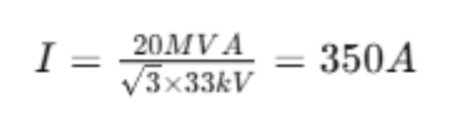
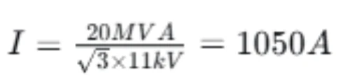
1. Calculate Transformer Full‑Load Current
33 kV side:
11 kV side:
2. Determine Required Protection Functions
- 87T differential (primary internal fault protection)
- 50/51 overcurrent (backup and external fault protection)
- 50N/51N earth fault
- REF (sensitive ground fault on 11 kV side)
- 49 thermal protection
- 24 overexcitation protection
- Buchholz and temperature monitoring via external inputs
3. Check CT Compatibility
- 33 kV side: use 500/1 A CT
- 11 kV side: use 1500/1 A CT
- Verify CT class (5P20 or equivalent) and saturation performance
4. Consider Transformer Inrush
Select relay with second‑harmonic restraint for differential protection.
5. Check Protection Coordination
Coordinate 50/51 settings with upstream feeder relay and downstream switchgear protection.
6. Determine Communication Requirements
Select relay with IEC 61850 support for SCADA integration.
Recommended Protection Scheme
| Protection | Function | Purpose |
|---|---|---|
| 87T | Differential | Internal transformer faults |
| 50/51 | Overcurrent | Backup protection |
| 50N/51N | Earth fault | Ground faults |
| REF | Restricted earth fault | Sensitive winding faults |
| 49 | Thermal | Overheating protection |
| 24 | V/Hz | Overexcitation protection |
Transformer Protection Relay Selection Checklist
Before selecting a relay, verify:
- [ ] Transformer rating (kVA/MVA)
- [ ] Primary voltage
- [ ] Secondary voltage
- [ ] Transformer vector group
- [ ] Winding configuration
- [ ] Grounding method
- [ ] Transformer impedance (%Z)
- [ ] Maximum load current
- [ ] Short‑circuit current (maximum and minimum)
- [ ] CT ratio (primary and secondary)
- [ ] CT class
- [ ] CT polarity
- [ ] Required ANSI protection functions
- [ ] Differential protection required?
- [ ] Earth fault protection
- [ ] REF required?
- [ ] Inrush current considered?
- [ ] Temperature protection
- [ ] Mechanical protection (Buchholz, pressure)
- [ ] Protection coordination
- [ ] Communication protocol
- [ ] SCADA integration
- [ ] Auxiliary power supply
- [ ] Environmental requirements
Common Mistakes in Transformer Relay Selection
Choosing a Relay Based Only on Transformer Voltage
Voltage is only one parameter. Protection functions, CT matching, and coordination often matter more.
Ignoring Transformer Capacity
A 5 MVA transformer does not have the same protection needs as a 50 MVA transformer.
Ignoring Vector Group
Differential protection requires vector group compensation. Incorrect settings cause false differential current.
Selecting the Wrong CT Ratio
If CT ratio is too low, the relay input may saturate. If too high, sensitivity may be insufficient.
Ignoring CT Saturation
Saturated CTs produce distorted current waveforms, delaying fault detection or preventing relay operation.
Forgetting Transformer Inrush Current
Inrush can cause nuisance tripping. Use harmonic restraint for differential relays and coordinate time delays.
Using Differential Protection Without Proper CT Matching
CT ratios and polarities must match on both sides of the transformer. Mismatch creates false differential current.
Ignoring Grounding Method
Earth fault protection depends on grounding. A grounded system needs different protection than an ungrounded system.
Not Coordinating Backup Protection
Overcurrent backup must coordinate with downstream devices and provide time for the differential relay to operate first.
Choosing More Protection Functions Than the Application Requires
More functions increase cost and configuration complexity. Select only needed functions.
How to Choose the Right Transformer Protection Relay for Different Applications?
Use this decision table for typical applications.
| Application | Typical Protection |
|---|---|
| Small distribution transformer (< 5 MVA) | 50/51, 50N/51N, thermal |
| Medium distribution transformer (5–20 MVA) | 50/51, 50N/51N, 49, optional REF |
| Large power transformer (> 20 MVA) | 87T, REF, 50/51, 49, 24, mechanical protection |
| Generator step‑up transformer | 87T, REF, 24, 50/51, thermal and mechanical protection |
| Critical industrial transformer | 87T + backup + monitoring |
| Renewable energy transformer | 87T or OC/EF + voltage/frequency functions as required |
Frequently Asked Questions
How do I select a transformer protection relay?
Start with transformer nameplate data: rating, voltage, vector group, grounding, and impedance. Then select protection functions based on transformer size and criticality.
What protection relay is used for a transformer?
Numerical transformer relays with 87T differential, 50/51 overcurrent, 50N/51N earth fault, REF, and 49 thermal functions are common for power transformers. Distribution transformers may use simpler relays with overcurrent and earth fault only.
What protection functions are required for a power transformer?
Power transformers typically require differential (87T), overcurrent (50/51), earth fault (50N/51N), restricted earth fault (REF), thermal (49), and overexcitation (24) protection.
Is differential protection required for every transformer?
No. Smaller distribution transformers (below 5 MVA) often use overcurrent protection only. Differential protection is recommended for transformers above 10 MVA or critical applications.
What is the difference between transformer differential and overcurrent protection?
Differential protection (87T) compares currents entering and leaving the transformer. It detects internal faults quickly. Overcurrent protection (50/51) detects excess current and provides backup protection for internal and external faults.
How do I select the CT ratio for transformer differential protection?
The CT ratio must match the transformer full‑load current on each side, considering voltage ratio and vector group. CTs on both sides must have the same class and suitable burden. The relay must compensate for CT ratio mismatch internally.
Why does transformer inrush current affect relay selection?
Inrush current can reach 8–12 times full‑load current during energization. Without harmonic restraint, the relay may misinterpret inrush as a fault and trip incorrectly.
When is REF protection required for a transformer?
REF protection is recommended for grounded transformers above 5 MVA. It provides sensitive protection for internal ground faults in the transformer winding.
What is the best protection relay for a 33 kV transformer?
For a 33 kV distribution transformer (5–20 MVA), a numerical relay with 50/51, 50N/51N, REF, and 49 functions is typical. For larger 33 kV transformers, add 87T differential and 24 overexcitation protection.
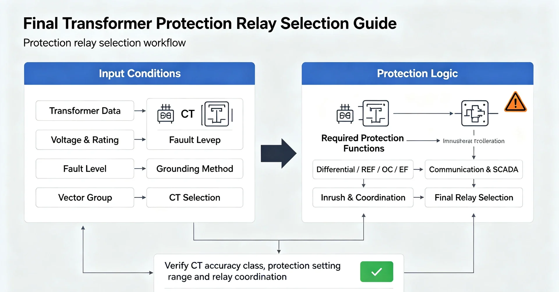
Final Transformer Protection Relay Selection Guide
Follow this engineering decision flow:
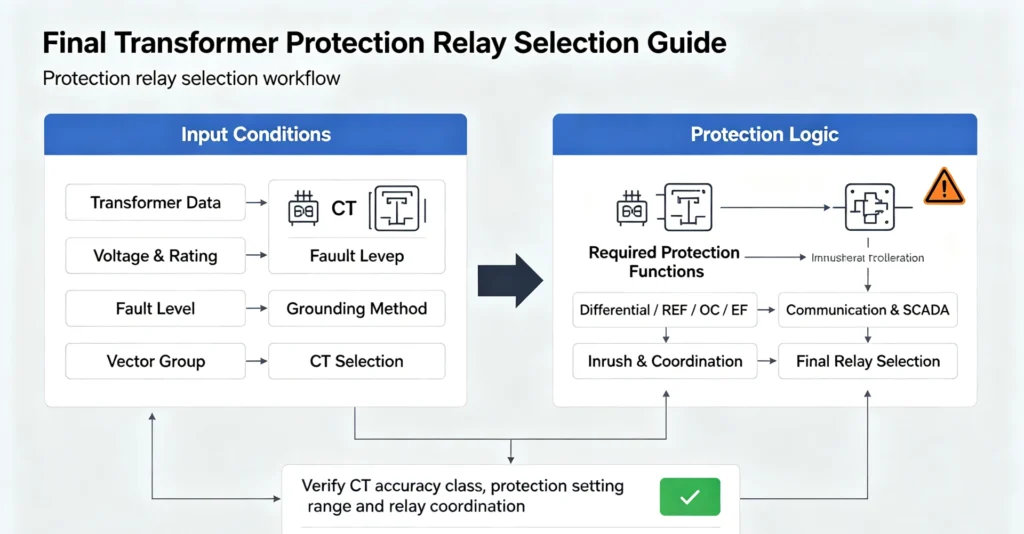
The right transformer protection relay is not simply the relay with the most protection functions. It is the relay whose protection scheme, CT inputs, settings, communication capabilities and operating characteristics match the transformer and the power system.
References
- IEEE Standard C37.91-2021 – Guide for Protecting Power Transformers.
- IEC 60255 Series – Measuring Relays and Protection Equipment.
- IEC 61850 – Communication Networks and Systems for Power Utility Automation.
- IEC 60044-1 – Instrument Transformers – Part 1: Current Transformers.
- IEEE Standard C57.12.00 – Standard General Requirements for Liquid-Immersed Distribution, Power, and Regulating Transformers.
- IEC 60909-0 – Short-Circuit Currents in Three-Phase AC Systems.
- CIGRE Technical Brochure 774 – Protection of Distribution Systems with Distributed Generation.



About Author

Hello, I'm Leno Zhang. I have 15 years of experience in the power relay protection industry with extensive pre-sales and after-sales project experience. Our company specializes in various complete sets of relay protection and automation equipment. I can assist customers in solving all practical on-site project challenges and provide optimal integrated solutions.
Tell Us Your Requirement
High Quality
Stable performance, reliable design, ensuring safe operation for power system protection and grid stability.
Fast Delivery
Timely delivery to support your urgent orders and project schedules efficiently and professionally at any time.
Best Warranty
Professional Warranty: Reliable after-sales support for stable relay protection and long-term customer satisfaction.