
-
Leon Zhang Sales Manager
-
Email: sale@relayprotect.com
-
Phone/WhatsApp: +86 13655813266

Type 1, 2 and 3 Surge Protection and Six Datasheet Numbers
Surge protection is a placement problem before it is a product: what Uc, In, Imax, Iimp and Up mean, and where Type 1, 2 and 3 devices belong.
What is surge protection and how do Type 1, 2 and 3 devices differ?
Surge protection gives a transient overvoltage a low-impedance path to earth before it reaches equipment, switching from open circuit to conducting in microseconds and back. IEC 61643-11:2025 and UL 1449:2021 define the ratings, IEC 62305 the lightning environment behind Type 1. Most damaging energy is generated inside the building, when a contactor coil or a drive switches off and its magnetic field collapses into a fast, high-voltage kick; a plant PLC sees that kick thirty times a day. A 6 kV impulse crosses a 2.5 kV withstand level in well under a microsecond, faster than any breaker or fuse. A metal-oxide varistor clamps in nanoseconds but its protection voltage rises with current; a gas discharge tube responds in tens of nanoseconds yet carries far more charge. Type 1 handles direct lightning, Type 2 distribution surges, Type 3 sensitive loads near the point of use. Setting review and quotation within 12 hours, MOQ 1, 7-15 working days.
Surge protection is the practice of giving a transient overvoltage a low-impedance path to earth before it reaches equipment, using a device that changes from open circuit to conducting in microseconds and then returns to open circuit. IEC 61643-11:2025 and UL 1449:2021 define how that device is rated and tested.
At a glance
- An SPD limits voltage by diverting current. It does not absorb the surge and it does not filter it out.
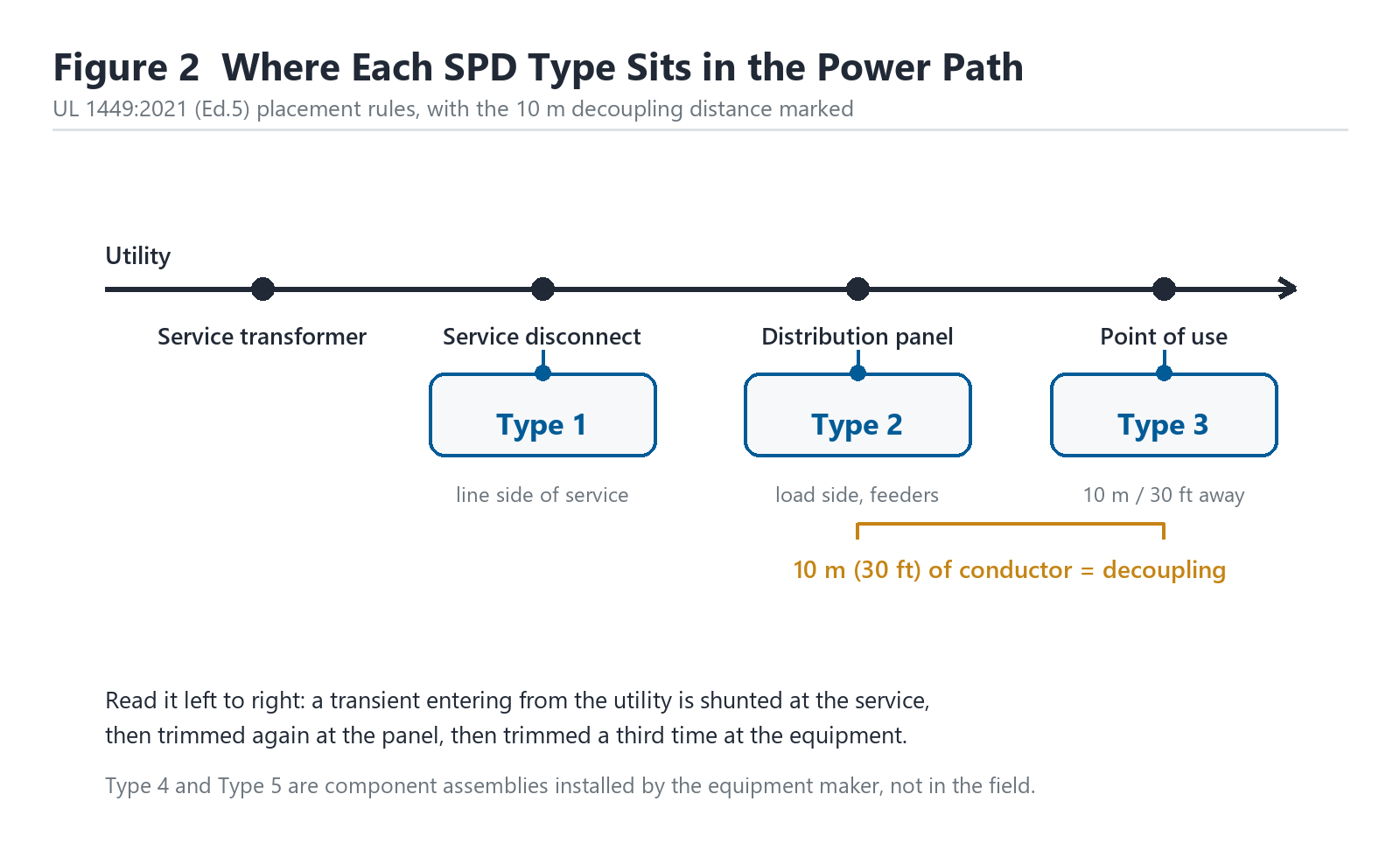
- UL 1449 Type 1 sits at or ahead of the service disconnect; Type 2 sits on the load side; Type 3 sits at the equipment.
- Uc must exceed the highest sustained voltage the device will see, including a 1.1 pu utility rise.
- In and Imax use the 8/20 microsecond wave. Iimp uses 10/350 and only applies to Class I or Type 1 devices.
- Up is measured at the terminals. A 1 m lead adds roughly 2.5 kV to that figure during a 20 kA discharge.
- Short-circuit current rating must equal or exceed the available fault current at the connection point.
- NEC 2026 Article 242 governs installation; 230.67 makes a service SPD mandatory in dwellings.
- An SPD that has sacrificed itself usually still carries load current. Only the status window tells you.
What surge protection actually does to a transient
A surge arrives in microseconds and carries far more energy than any semiconductor can absorb. So the device does the only thing physics allows: it offers the current a shorter route to the earth bar than the route through your equipment, and it holds the voltage across its terminals at a level the equipment can survive while that current flows.
That is the whole mechanism. Everything else on a datasheet describes how well, how long and under what conditions it does that.
Most of the energy that damages equipment never arrives from the sky. It is generated inside the building, when a contactor coil, a drive or any inductive load is switched off and the stored magnetic field collapses into a fast, high-voltage kick. A plant PLC that drops a 5 kW motor sees that kick on its own supply terminals, thirty times a day, for years.
Lightning is the dramatic case. Switching is the one that quietly retires solid-state controls.
Selecting a relay for a live project?
Send the system voltage, CT ratio and tripping scheme. Our engineers confirm the model and reply within 12 hours.
The left of the red curve is where equipment dies. A 6 kV impulse crosses a 2.5 kV withstand level in well under a microsecond, which is faster than any breaker, fuse or relay can respond. Overcurrent devices protect conductors from thermal damage over seconds. They are irrelevant here.
How a surge protective device clamps a wave
Three components do almost all of the work in low-voltage equipment, and most commercial devices combine them.
A metal-oxide varistor changes resistance with applied voltage. Below its breakover point it is a near-open circuit drawing microamps; above it, the resistance collapses and tens of kiloamps pass through a disc a few centimetres across. The response is fast, in the nanosecond range, and the clamping is soft, so Up rises with current.
A gas discharge tube is slower, tens of nanoseconds, but it can carry far more charge. It works by arc, which means it has a follow current while the arc persists and a voltage drop that stays low and roughly constant.
A suppressor diode array clamps hardest and fastest, with a sharp knee, but its energy handling is the smallest of the three. It appears at the point of use, protecting a signal or a low-power board.
Combining a varistor with a spark gap gives a device that survives a direct hit and still clamps tightly. The varistor takes the first microseconds, the gap takes the bulk charge, and the varistor resumes control as the wave decays.
Six datasheet numbers that decide the application
Catalogues quote a dozen figures. Six of them decide whether the device survives and whether it protects.
| Parameter | What it states | Typical value, 400 V TN-S board | What goes wrong |
|---|---|---|---|
| Uc, maximum continuous operating voltage | The highest rms voltage the device may sit at indefinitely | 385 V or 440 V | Uc below the sustained rise, and the varistor cooks on a healthy network |
| In, nominal discharge current | Peak current it survives 20 times, 8/20 us wave | 20 kA per pole | Read as a maximum, so a 100 kA site is fitted with 20 kA |
| Imax, maximum discharge current | Peak current it survives once, 8/20 us wave | 40 kA per pole | Treated as repeatable, when it is a single-event figure |
| Iimp, impulse current | Peak current it survives, 10/350 us wave | 12.5 kA or 25 kA per pole | Quoted on a Type 2 device that was never tested to that wave |
| Up, voltage protection level | Residual voltage at the terminals at In | 1.5 kV at 20 kA | Compared across devices tested at different currents |
| Short-circuit current rating | Fault current the device can be connected to and fail safely | 25 kA, 50 kA or 100 kA | Lower than the available fault current, so failure is violent |
Table 1. The six figures to compare before price, taken from IEC 61643-11:2025 declarations.
Two of these are routinely misread. In is not a maximum; it is the current the device can take twenty times and still be within its declared drift. Imax is the single-event ceiling, and a device that has seen Imax is at end of life whatever the status window says.
Type 1, Type 2 and Type 3: where each surge protection device belongs
The type is a placement class, not a quality grade. UL 1449:2021 defines it by where the device may be installed, and IEC 61643-11:2025 defines a matching test class.
| Type | Permitted location | IEC test class | Needs a dedicated OCPD |
|---|---|---|---|
| Type 1 | Line side of the service disconnect, or load side | Class I, tested with Iimp, 10/350 us | No, it is listed for the line side |
| Type 2 | Load side of the service disconnect, at any panel | Class II, tested with In, 8/20 us | Usually, per the manufacturer’s marked rating |
| Type 3 | At the equipment, at least 10 m of conductor from the panel | Class III, combination wave | Yes, a branch breaker or the integral one |
| Type 4 | Inside equipment, component assembly | Class tested as a component | Integral to the assembly |
| Type 5 | Discrete component, not a field-installed product | Component level only | Not applicable |
Table 2. Placement classes from UL 1449:2021 Edition 5, with the IEC 61643-11:2025 test class each corresponds to.
The 10 m figure in the Type 3 row is not decorative. A Type 3 device relies on the impedance of the branch circuit to limit the current reaching it, and the listing assumes at least 10 m of conductor. Mount one at the panel and it faces a current it was not tested for.
What a surge protection device is rated for at each board
Ratings move with exposure and with position. A device at the service sees the full incoming wave; one at a sub-panel sees a wave already trimmed and delayed.

Exposure is a site question, not a catalogue question. A coastal pumping station with an exposed 11 kV overhead line, a long cable run and a history of card failures needs more than a shielded urban office with the same 400 A service. If the site has recorded equipment losses after storms, that history outranks any generic table, including this one.
Power panel surge protection: sizing the device and its breaker
At a distribution panel the practical questions are how many poles, which modes, and what protects the device itself.
Poles follow the system. A three-phase four-wire TN-S board needs protection from each phase to neutral and from neutral to earth, which most manufacturers supply as a three-pole plus neutral device with a declared combined mode. A corner-earthed delta or an IT system changes that pattern, and a device selected for TN will not simply work there.
| Panel size | Typical device | Per-pole In | Up target | Dedicated breaker |
|---|---|---|---|---|
| 100 A single-phase dwelling | Type 2, two-pole | 10 kA to 20 kA | 1.0 kV or lower | 2-pole, 30 A to 60 A per marking |
| 200 A dwelling or small shop | Type 2, two-pole | 20 kA | 1.0 kV or lower | 2-pole, 60 A per marking |
| 400 A three-phase board | Type 2, three-pole plus N | 20 kA to 40 kA | 1.5 kV or lower | 3-pole, 63 A to 125 A |
| 800 A to 1600 A main board | Type 1 or Type 2, four-pole | 40 kA to 50 kA | 1.5 kV or lower | Integral or per marking |
Table 3. Power panel surge protection sizing for TN-S systems; the breaker rating always comes from the device marking, not from this table.
That last point causes more failures than any other detail on this page. The nameplate on the SPD states the maximum overcurrent device it may be connected behind, and that figure is chosen for the device’s internal wiring, not for the panel. Fit it behind a 200 A main breaker because that breaker was spare, and the device has no protection against its own failure.
Keep the connecting leads short and twist them.
Coordination: why two devices beat one large one
A single device at the service limits the incoming wave to its Up, which may be 1.5 kV. That is survivable for a panel, and still far above the few hundred volts a control card wants. A second device closer to the load finishes the job.
The two must not fight. If the downstream device conducts first, it takes the full current and dies young. The impedance of the cable between them provides the separation: about 10 m of conductor, or a decoupling inductor where that length is unavailable, lets the upstream device clamp first and the downstream one see only the residue.
Energy coordination is the formal version of the same idea, and it is declared by the manufacturer as a tested pair. Two devices from different makers, chosen by kA rating alone, have no declared coordination and may share current in an order nobody predicted.
Lead length, bonding and the 2.5 kV you did not order
Up is measured across the device terminals with a defined test setup. In a panel, the device is connected by leads, and those leads have inductance.

Take the arithmetic seriously. A cable pair has roughly 1 microhenry per metre. During an 8/20 microsecond discharge at 20 kA, the wavefront rises in about 8 microseconds, so the rate of change is around 2.5 kA per microsecond. Multiply inductance by that rate and every metre of lead contributes about 2.5 kV on top of Up.
So a device with a 1.5 kV Up, mounted 1 m from the busbar with two 1 m leads, presents roughly 4 kV to the load. The equipment withstand level for a 400 V installation is commonly taken as 2.5 kV or 4 kV depending on category. The margin has gone.
Bonding matters for the same reason. The return path from the device to the earth bar is part of the loop, and a 2 m green-and-yellow conductor with two bends behaves like an inductor, not a wire. Short, straight and bolted to the bar is the whole specification.
Surge arrester or surge protective device
The two names describe different hardware either side of 1 kV. A surge arrester is a medium-voltage or high-voltage device, coordinated with insulation levels and rated by its maximum continuous operating voltage and residual voltage at a given discharge current. An SPD is the low-voltage product this article has been describing.
NEC 2026 splits them the same way inside Article 242: Part II covers SPDs at 1,000 V and below, Part III covers surge arresters above it. Replacing one with the other is not a substitution, it is a category error. An arrester has no Up in the SPD sense, and an SPD will not survive the insulation coordination duty of a 33 kV bus.
What the codes require in 2026
NEC 2026 Article 242 replaced the old Articles 280 and 285 in the 2020 cycle, and the 2026 text tightened two things: SPDs at 1,000 V or less must be listed, and reconditioned units are not permitted. Section 242.2 carries the listing rule, 242.8 forbids installation where the available fault current exceeds the marked short-circuit current rating, and 242.9 requires a functioning indicator that can be seen without moving conductors.
Beyond Article 242, four mandates now pull surge protection into ordinary work. Section 230.67 requires an SPD on dwelling service equipment. Section 215.18 requires one on feeders supplying dwelling units, dormitories, hotel guest rooms and nursing-home patient sleeping areas, and the 2026 edition adds sleeping areas of fire stations, police stations and ranger stations. Section 695.15 covers fire pump controllers, 700.9 emergency systems, 708.8 critical operations power systems and 670.7 life safety circuits on industrial machinery.
NFPA 780:2026 rewrote its surge clause into Section 4.19 and now asks for the surge schedule to list SPDs, arresters and surge protectors separately, each with its short-circuit rating and status indication. Its risk annex also switched from flash density to strike-point density, with a 1.7 multiplier where only flash density is known, so an older risk assessment gives a different answer.
How these devices fail, and how failure should look
Every failure mode ends with the same question: does the panel still have protection, and does anyone know it does not.
| Failure mode | Mechanism | What you observe | Correct response |
|---|---|---|---|
| Varistor ageing | Leakage rises with each surge until the disc runs hot | Warm enclosure, discoloured window, drifting Up | Replace the cartridge, log the event count |
| Thermal disconnector open | Internal fuse or spring link clears the aged disc | Status window red or blank, load still energised | Replace; the circuit is running unprotected |
| Temporary overvoltage | Sustained rise above Uc, often a lost neutral | Device destroyed, upstream protection operated | Fix the source fault before fitting a new device |
| Fault current above rating | Available fault current exceeds the marked SCCR | Split enclosure, scorching, ejected parts | Re-select the device and its OCPD, review the board |
| Wrong mode coverage | Phase-to-neutral only, on a system needing N to PE | No visible damage, repeated electronics loss | Add the missing mode; check the earthing system first |
Table 4. Five failure patterns from commissioning and service records, with the observable symptom for each.
The middle row is the one that costs money. A device that has done its job and disconnected itself leaves a live board with a green light elsewhere and no protection at all. Unless someone reads the window and writes it down, the loss is only discovered when the next storm takes a drive.
Nuisance tripping is the mirror image. A varistor nearing end of life leaks enough current to trip the dedicated breaker, and the electrician who resets it restores the load without restoring protection. If the same breaker opens twice in a season with no fault on the circuit, test the device before resetting it a third time.
Commissioning, marking and maintenance
Three checks belong in the commissioning sheet. Confirm the marked SCCR against the calculated fault level at that point, not against the board’s nominal rating. Confirm that every protection mode the system needs is present, phase to neutral and neutral to earth. Confirm the indicator is visible with the enclosure closed, because a window behind a door is a window nobody opens.
After that, maintenance is a visual routine with a written record. Read the status window at every service, note the date, and replace cartridges as a set rather than one at a time. A mixed-age bank shares current unevenly, and the oldest disc takes the largest share.
When surge protection is the wrong answer
An SPD treats a symptom. Fitting one to a site with a wiring defect hides the defect and adds a component that will fail.
- A lost or high-resistance neutral. The resulting overvoltage sits above Uc for seconds, and no low-voltage SPD is rated for that. Fix the neutral first; the SPD is not a substitute for it.
- Repeated electronics loss on one circuit only. That pattern points at a local source, a switched inductive load or a shared neutral, not at an incoming surge.
- Missing or inadequate bonding. An SPD with no low-impedance path to earth has nowhere to send the current, and the voltage simply appears elsewhere in the building.
- A fault level above the device rating. Adding a device with a 25 kA SCCR to a board with 40 kA available creates an enclosure failure, not protection.
- Lightning protection design. Direct strikes need air terminations, down conductors and earth termination resistance, which is a different discipline and a different standard.
Each of the five is a scope error, and each is cheaper to fix at the cause than at the symptom.
Frequently asked questions
What is the difference between Type 1 and Type 2?
Type 1 is listed for the line side of the service disconnect and is tested with a 10/350 microsecond impulse current, so it can face a partial lightning current. Type 2 is listed for the load side and tested with an 8/20 microsecond wave. A Type 1 device may also be installed on the load side, but a Type 2 device may not move to the line side.
What kA rating do I need?
Match the rating to exposure, not to floor area. A shielded urban board with no storm history is usually served by a 20 kA per-pole Type 2 device. An exposed site with overhead lines and a record of card failures warrants 40 kA or more, plus a second stage at the sub-panel. Higher ratings buy endurance, not a lower Up.
Does a surge protective device protect against a direct lightning strike?
No. A device at the service can absorb the surge coupled into the incoming conductors, and a Type 1 unit is tested for a partial lightning current. A direct strike needs an external lightning protection system designed to NFPA 780:2026 or IEC 62305, with the SPD acting only as part of the coordinated set.
Why did my device fail within a year?
Three causes dominate: Uc too low for the actual network voltage, a missing or oversized upstream breaker letting through more energy than the device was rated for, and a temporary overvoltage from a loose neutral. Check the recorded voltage at the board over a week before blaming the product.
Can I install one myself?
Only a plug-in Type 3 unit at an outlet. Anything connected inside a panel involves live busbars, a torque specification and a short-circuit current rating that must be checked against the fault level. That work belongs to a licensed electrician, and in most jurisdictions the inspection is part of the permit.
How long does one last?
There is no service life in years, only a count of surges. A device at an exposed service may see its declared number of events within two storm seasons and sit unprotected afterwards. That is why the status window and a written log matter more than the warranty period.
Do I need a device at every panel?
Not every panel, but every level where the wave can enter or be re-amplified. Service entrance, then the main distribution board, then a sub-panel feeding sensitive loads, with a Type 3 unit at the equipment itself. Coordination between the stages is what makes the set work.
Conclusion
Surge protection comes down to four numbers and one installation habit: Uc above the sustained voltage, In and Imax matched to exposure, Up below the withstand of what you are protecting, and an SCCR above the available fault current. Then keep the leads short and the bonding straight, because the installation adds voltage that no datasheet mentions.
Check the status window at every service and write down what you see. A device that has already sacrificed itself still carries load current, and a site that believes it is protected is harder to fix than one that knows it is not.
Related reading
- Substation equipment and auxiliaries, where the earthing and bonding that an SPD depends on is designed.
- Secondary equipment in distribution rooms, covering the devices that sit beside the SPD in a panel.
- Circuit breakers and their short-circuit ratings, for the fault level that sets the SPD’s SCCR requirement.
- Emergency generator panels, where transfer switching produces the switching surges an SPD has to absorb.
- Protection of switchgear, for the coordination between overcurrent and overvoltage devices.
Sources and standards
| Source | What it covers | Type | Edition |
|---|---|---|---|
| IEC 61643-11:2025 | SPDs for AC low-voltage systems: requirements and test methods | Standard | 2025, Ed. 2 |
| IEC 61643-01:2024 | Common requirements and test methods for all SPDs | Standard | 2024 |
| IEC 61643-12:2020 | Selection and application principles for low-voltage SPDs | Standard | 2020, Ed. 3 |
| IEC 61643-31:2018 | SPDs for photovoltaic installations | Standard | 2018 |
| UL 1449:2021 | Surge protective devices, Types 1 to 5, US listing basis | Standard | 2021, Ed. 5, rev. 2025 |
| ANSI/IEEE C62.41.2:2002 | Characterisation of surges in low-voltage AC circuits, test waves | Recommended practice | 2002 |
| IEEE C62.45:2002 | Guide to surge testing of low-voltage equipment | Guide | 2002 |
| NFPA 70, NEC 2026 | Article 242 overvoltage protection; 230.67, 215.18, 695.15 | Code | 2026 |
| NFPA 780:2026 | Lightning protection systems, surge clause 4.19 and risk annex | Standard | 2026 |
Table 5. Standards cited above, with the edition each figure came from.
Field observations in this guide come from our own commissioning and service records on 400 V boards and 11 kV substations between 2023 and 2026. They describe those installations and nothing beyond them.
If the selection has to be checked against your switchboard, send the single-line and the ratings.
Devices that detect or record transient overvoltage events: ATN-800H arc flash protection relay; APQ-9100H power quality monitor; digital fault recorder panel.
About Author

Hello, I'm Leon Zhang. I have 15 years of experience in the power relay protection industry with extensive pre-sales and after-sales project experience. Our company specializes in various complete sets of relay protection and automation equipment. I can assist customers in solving all practical on-site project challenges and provide optimal integrated solutions.
Tell Us Your Requirement



High Quality
Stable performance, reliable design, ensuring safe operation for power system protection and grid stability.
Fast Delivery
Timely delivery to support your urgent orders and project schedules efficiently and professionally at any time.
Best Warranty
Professional Warranty: Reliable after-sales support for stable relay protection and long-term customer satisfaction.