

-
Leon Zhang sales consultant
-
Email: zxl635973785@gmail.com
-
Phone/WhatsApp: +86 13655813266
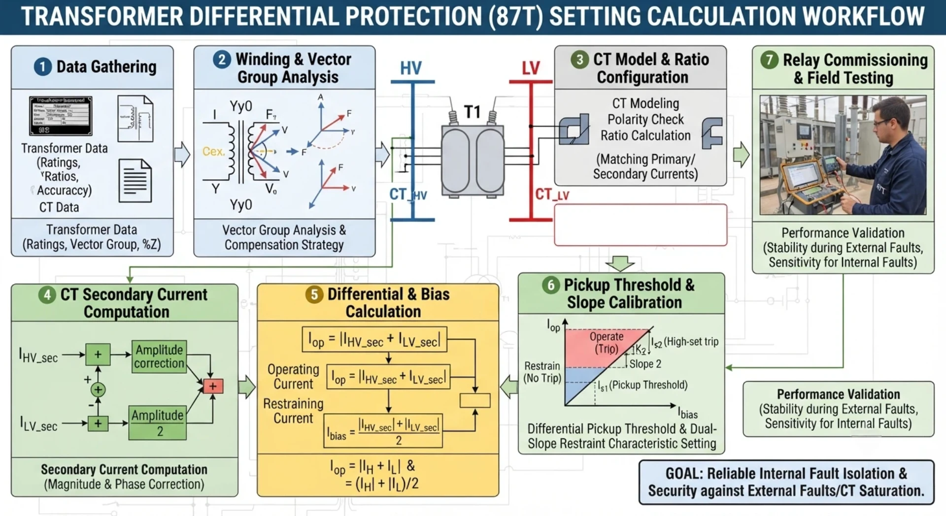
Differential Protection Relay Setting Calculation: Formulas, Parameters and 87T Example
Differential protection relay setting calculation is the process of determining the operating current, restraint characteristics, bias slope, harmonic restraint and other protection parameters required for reliable differential protection.
For transformer differential protection, the calculation normally starts with the transformer rated power, voltage ratio, vector group, CT ratios and CT characteristics. These values are then used to determine the compensated relay currents, differential current, restraint current and appropriate protection thresholds.
This guide explains the main calculation steps and provides a practical 87T transformer differential protection example. The final relay settings should always be checked against the relay manufacturer’s characteristics, transformer protection study, CT data and the applicable project or utility requirements.
What Is Differential Protection Relay Setting Calculation?
Differential protection relay setting calculation is the process of determining the optimal operating thresholds and characteristic parameters.
Its core objectives include:
- Ensuring reliable detection of internal transformer faults (such as turn-to-turn faults and phase-to-phase short circuits)
- Maintaining stability and preventing misoperation under abnormal conditions, including external faults, inrush currents, and CT saturation
- Deriving key setting values by analyzing transformer nameplate data, CT ratios, vector group compensation, and fault current levels
- Key setting values include: differential current pickup value, slope of percentage restraint characteristic, harmonic restraint ratio, and tripping time delay
- Achieving an optimal balance between sensitivity (detecting minor internal faults) and security (preventing false trips)
Proper setting calculation is a critical step in relay coordination studies and protection scheme commissioning.
For the operating principle, see our detailed guide on Working Principle.
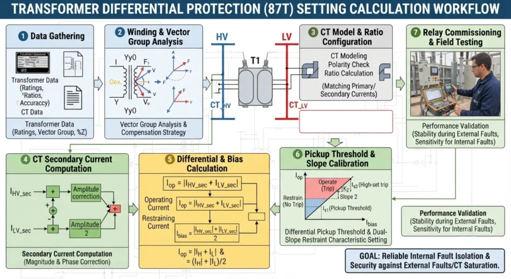
Data Required for Differential Protection Relay Setting Calculation
| Data | Symbol / Example | Why It Matters |
|---|---|---|
| Transformer Rated Power | S | Rated current calculation |
| HV Rated Voltage | U₁ | HV current calculation |
| LV Rated Voltage | U₂ | LV current calculation |
| Vector Group | YNd11 | Phase compensation |
| Transformer Impedance | Z% | Fault current assessment |
| HV CT Ratio | 400/1A | CT secondary current |
| LV CT Ratio | 1200/1A | CT secondary current |
| CT Class | 5P20 / PX | CT performance |
| CT Secondary Current | 1A / 5A | Relay input |
| System Frequency | 50/60 Hz | Protection configuration |
Step 1: Calculate Transformer Rated Current
The first step in differential protection setting calculation is to determine the rated currents on both sides of the transformer. These values serve as the base reference for all subsequent calculations, including CT ratio selection, vector group compensation, and differential current scaling.
Formula:
For a three-phase transformer, the rated line current is calculated as:
I=3×US
Where:
- I = Rated line current (A)
- S = Transformer apparent power (kVA or MVA)
- U = Line-to-line voltage (kV)
Example:
Consider a 63 MVA transformer with a voltage ratio of 132/33 kV and vector group YNd11.
HV Side Calculation:
IHV=3×13263,000
IHV=228.6363,000≈275.6 A
LV Side Calculation:
ILV=3×3363,000
ILV=57.1663,000≈1102.5 A
Result Summary:
| Side | Voltage (kV) | Rated Current (A) |
|---|---|---|
| HV | 132 | 275.6 |
| LV | 33 | 1102.5 |
These rated current values will be used in the next steps for CT ratio selection and setting calculations.
Step 2: Calculate CT Secondary Current
After determining the transformer rated currents on both sides, the next step is to calculate the actual secondary currents seen by the relay, based on the selected CT ratios. These values are essential for verifying that the CT secondary currents fall within the relay’s measurement range and for preparing the subsequent amplitude and phase compensation steps.
Formula:
ICT=CT ratioIprimary×ICT,rated
Where:
- I_CT = CT secondary current (A)
- I_primary = Primary current (transformer rated current on the relevant side) (A)
- CT ratio = CT primary rating (A)
- I_CT,rated = CT secondary rated current, typically 1A or 5A (A)
Example:
Using the same 63 MVA, 132/33 kV transformer from Step 1:
HV Side:
CT ratio: 400/1A
IHV,sec=400275.6×1
IHV,sec=0.689×1≈0.689 A
LV Side:
CT ratio: 1200/1A
ILV,sec=12001102.5×1
ILV,sec=0.919×1≈0.919 A
Result Summary:
| Side | CT Ratio | CT Secondary Current (A) |
|---|---|---|
| HV | 400/1A | 0.689 |
| LV | 1200/1A | 0.919 |
Important Note:
The two relay-side currents are not necessarily identical before the relay’s amplitude and phase compensation. This difference arises from the selection of CT ratios, transformer voltage ratio, and vector group configuration. The compensation method employed depends on the specific relay architecture and the project configuration. Some relays perform compensation internally based on user-entered parameters, while others may require external interposing CTs or software-based adjustments. Proper handling of this discrepancy is critical to ensure that the relay sees balanced currents under normal load conditions.
Step 3: Calculate Differential Current
Once the CT secondary currents on both sides have been determined, the differential current can be calculated. However, it is important to recognize that the differential current is not simply obtained by subtracting the two CT secondary current magnitudes directly.
General Expression:
Idiff=∣I1−I2∣
Where:
- I₁ = Current from one side of the transformer (e.g., HV side), referred to the relay’s reference
- I₂ = Current from the other side (e.g., LV side), referred to the same reference
Critical Requirement:
I₁ and I₂ must first be converted and compensated according to the relay’s defined current reference and the transformer vector group. Direct subtraction of the raw HV and LV CT secondary currents is mathematically incorrect, as these currents may differ in magnitude, phase angle, and reference direction. The relay applies internal algorithms to align both currents to a common reference system before calculating the differential quantity.
Operating Conditions:
Normal Condition
Under normal load or through-fault conditions, the compensated currents from both sides are approximately equal:
I1≈I2
As a result, the differential current remains small:
Idiff≈0
The relay remains stable and does not issue a trip command.
External Fault (Through-Fault)
During an external fault outside the transformer zone, the currents on both sides remain largely balanced in theory. However, CT errors, saturation, or mismatched transient responses may produce a residual differential current. To prevent unwanted tripping under these conditions, the relay employs a restraint characteristic (percentage restraint or biased differential protection) that increases the operating threshold as the through-current increases.
Internal Fault
When a fault occurs within the transformer protection zone (e.g., winding short circuit, core fault, or terminal fault), the balanced current relationship is disrupted. The compensated currents I₁ and I₂ become significantly different, causing the differential current to rise sharply:
Idiff≫0
If the differential current exceeds the relay’s operating characteristic (considering both the pickup value and the restraint quantity), the relay issues a trip command to isolate the transformer.
Summary of Operating States:
| Condition | Differential Current | Relay Response |
|---|---|---|
| Normal | Small (I₁ ≈ I₂) | Stable, no trip |
| External Fault | Residual (restrained by through-current) | Stable, no trip |
| Internal Fault | Large (I₁ ≠ I₂) | Trip if characteristic exceeded |
Step 4: Calculate Restraint or Bias Current
The restraint current (also referred to as bias current or through-current) is used in percentage differential protection to establish the relay’s operating boundary. It represents the magnitude of current flowing through the transformer under normal or external fault conditions and serves as the reference against which the differential current is compared.
Common Formula:
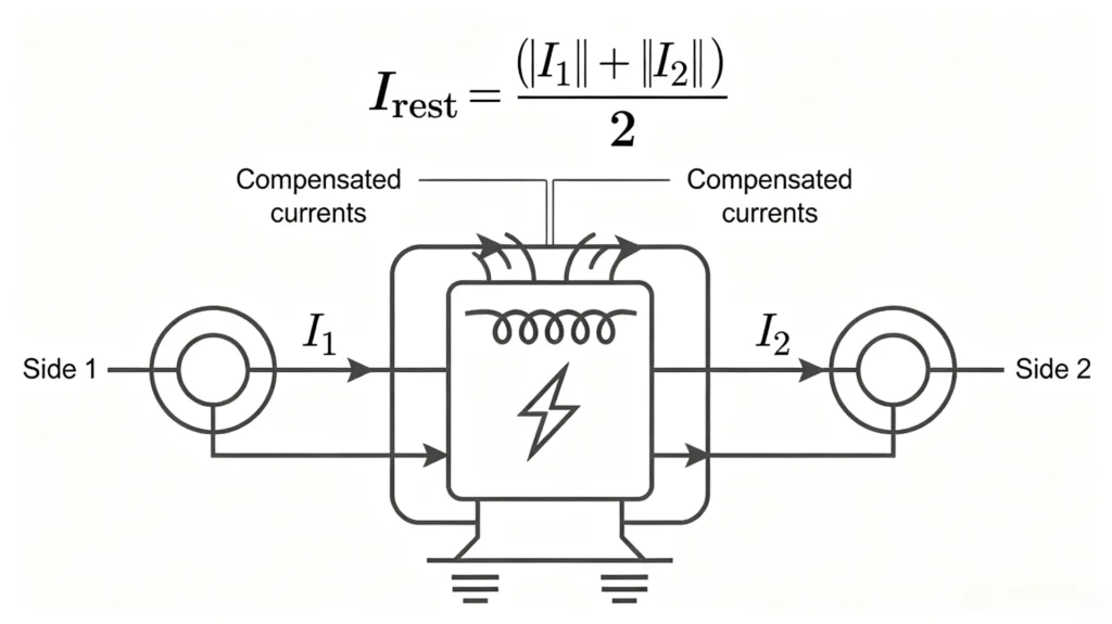
One widely used definition of restraint current is the average of the two compensated currents:
Irest=2∣I1∣+∣I2∣
Where:
- I₁ = Compensated current from one side (e.g., HV side)
- I₂ = Compensated current from the other side (e.g., LV side)
Other Possible Definitions:
Depending on the relay manufacturer and protection philosophy, alternative restraint current formulas may be used, including:
- Maximum of the two currents: Irest=max(∣I1∣,∣I2∣)
- Vectorial sum (for certain relay types): Irest=∣I1+I2∣ (under through-fault conditions)
- Weighted sum with different weighting factors for each side
Important Note:
The exact restraint-current definition varies between relay manufacturers. Always use the calculation method specified in the relay manual when converting the calculation into actual settings. Using an incorrect restraint formula during the setting process may lead to either over-sensitivity (risk of false tripping) or under-sensitivity (delayed or failed operation for internal faults).
Purpose of Restraint Current in Protection Characteristic:
Once both the differential current (I_diff) and the restraint current (I_rest) are determined, the relay plots the operating point on its characteristic curve. The relay operates only when:
Idiff>f(Irest)
where f(I_rest) defines the relay’s trip characteristic (typically a dual-slope or single-slope curve with a minimum pickup threshold). This principle ensures stability during high through-fault currents while maintaining sensitivity for low-magnitude internal faults.
Step 5: Calculate Differential Protection Bias Slope
The bias slope (also known as the percentage restraint slope) defines the relationship between the differential current and the restraint current, establishing the relay’s operating boundary across different fault current levels. Proper slope selection is critical to ensure relay security during external faults and sensitivity for internal faults.
Why Is a Bias Slope Required?
Under ideal conditions, the differential current should be zero for normal load and external faults. However, in practice, several factors can produce a spurious differential current:
- CT ratio error – Mismatch between actual and rated CT ratios due to manufacturing tolerances
- CT saturation – Distorted secondary current waveforms during high-current through-faults, particularly with remnant flux in the CT core
- OLTC variation – Changes in transformer voltage ratio that alter the current balance
- Wiring errors – Incorrect CT polarity, connection faults, or different cable impedances
- Measurement errors – Relay internal measurement inaccuracies, quantisation errors, or signal chain drift
The bias slope ensures that the relay’s operating threshold increases with the through-current level, compensating for these error sources and preventing unwanted tripping under external fault conditions.
Slope Characteristics
Most transformer differential relays employ a dual-slope or multi-slope characteristic to optimise performance across different operating regions.
Slope 1 (Low-Current Region)
Slope 1 applies to the low restraint current region, typically corresponding to normal load or light through-fault conditions. In this region:
- The differential current is primarily affected by steady-state errors such as CT ratio mismatch and tap changer variations
- A lower slope value provides high sensitivity for detecting minor internal faults
- This slope is effective at currents up to approximately 1.0 to 2.0 per unit of transformer rated current
Slope 2 (High-Current Region)
Slope 2 applies to the high restraint current region, typically associated with severe external faults or heavy through-fault conditions. In this region:
- The restraint current increases significantly, and CT saturation becomes the dominant error source
- CT saturation introduces substantial differential current, particularly during the first few cycles of fault
- A higher slope value increases the operating threshold, ensuring relay stability during severe external faults
- This slope typically applies for restraint currents above approximately 2.0 to 3.0 per unit
Calculation Logic
The slope is determined by the maximum differential current expected under the worst-case external fault conditions, divided by the corresponding restraint current:
Slope≥IrestIdiff,max
Where:
- I_diff,max = Maximum expected differential current during an external fault, considering CT errors and saturation
- I_rest = Restraint current at the same fault level
Important Note:
This is a simplified engineering relationship for conceptual understanding. The actual relay characteristic may use different definitions of differential and restraint current, multiple slopes, or piecewise characteristics. Modern numerical relays often implement dual-slope, triple-slope, or even adaptive characteristics with additional features such as:
- Cross-blocking between phases
- CT saturation detection and transient blocking
- Differential current vectorial summation (not simply magnitude)
Typical Setting Ranges (for reference only):
| Slope | Typical Range | Application Region |
|---|---|---|
| Slope 1 | 20–35% | Low-current region (normal load to light through-faults) |
| Slope 2 | 50–80% | High-current region (severe external faults with CT saturation) |
Final Recommendation:
Always refer to the specific relay manufacturer’s manual for the exact slope calculation method, characteristic curve shape, and setting procedure. Different relays implement bias slope characteristics with varying definitions, breakpoints, and special features. Use the manufacturer’s settings calculation software or tool to validate and verify the settings under all possible operating and fault scenarios.
Step 6: Determine Differential Pickup Current
The differential pickup current (Idiff>) is the threshold above which the relay initiates tripping. It is the most fundamental setting, directly determining both sensitivity to internal faults and stability against maloperation.
The Core Challenge
The pickup setting must satisfy two conflicting requirements:
- Sensitivity – Low enough to detect internal faults, including minor turn-to-turn short circuits.
- Stability – High enough to override spurious differential currents caused by CT errors, CT saturation, inrush currents, OLTC variations, and measurement errors.
The Design Constraint
These two requirements define a critical design window:
Ipickup>Iunbalance,max
The pickup must exceed the maximum differential current expected under non-fault conditions to ensure stability.
Ipickup<Iinternal−fault,min
The pickup must be below the minimum differential current for any internal fault to ensure sensitivity.
Practical Range
Typical pickup settings range from 15–40% of transformer rated current:
- Higher values (30–40%) for transformers with wide tap ranges or poorly matched CTs
- Lower values (15–25%) for applications with well-matched CTs and stable conditions
Final Requirement
The final pickup setting must satisfy both stability and sensitivity requirements. Verify the setting through calculation of maximum unbalance current, review of minimum internal fault current, and validation using the relay manufacturer’s tools.
Step 7: Estimate Maximum Unbalanced Current
Under ideal conditions, the differential current during normal operation and external faults should be zero. In practice, however, various error sources produce a residual or spurious differential current. Estimating the maximum expected unbalanced current is essential for determining the minimum pickup threshold and slope characteristic that ensure stability.
Key Error Sources
The following factors contribute to unbalanced current:
- CT ratio error – Manufacturing tolerances and variations in CT accuracy class
- CT excitation characteristics – Differences in magnetizing curves and knee-point voltages
- CT saturation – Distorted secondary currents during high-current through-faults, particularly with DC offset and remnant flux
- OLTC range – Tap changer variations that alter the transformer effective turns ratio
- Transformer ratio tolerance – Nameplate tolerance on the transformer rated voltage ratio
- Relay measurement error – Internal analog input errors, quantisation noise, and calculation precision
- Wiring resistance – Differences in cable impedances and burden on CT secondary circuits
Engineering Approach
A practical estimation is typically based on the CT accuracy class and the maximum anticipated through-fault current:
- For CTs with class 5P or 10P, the maximum composite error is typically specified at the rated accuracy limit factor (ALF). Under through-fault conditions, this error can reach several percent
- Additional allowance must be made for OLTC range (e.g., ±10% or ±15%) and transformer ratio tolerance (±1% to ±2%)
- Relay measurement errors are typically small (less than ±1%) in modern numerical relays
Practical Range
As a general reference for preliminary estimation, the maximum unbalanced current often falls in the range of 5–15% of transformer rated current, depending on CT quality, application requirements, and fault level.
Purpose of This Estimate
The maximum expected unbalanced current becomes one of the key references for selecting the minimum stable differential pickup and bias characteristic. This estimate ensures that the relay remains stable under worst-case normal and external fault conditions while maintaining adequate margin for internal fault detection.
Complete 87T Differential Protection Setting Calculation Example
This section provides a step-by-step calculation example for a transformer differential protection relay setting. The example is for illustration purposes only and demonstrates the calculation workflow. Final settings must be validated using the specific relay manufacturer’s tools and verified through site commissioning tests.
Step 1: Transformer Data
| Parameter | Value |
|---|---|
| Rated Power | 63 MVA |
| HV | 132 kV |
| LV | 33 kV |
| Vector Group | YNd11 |
| Impedance | 10.5% |
| HV CT | 400/1A |
| LV CT | 1200/1A |
| Frequency | 50 Hz |
Step 2: Rated Current
HV side:
IHV=3×13263,000≈275.6 A
LV side:
ILV=3×3363,000≈1102.5 A
Step 3: CT Secondary Current
HV side (400/1A CT):
IHV,sec=400275.6×1≈0.689 A
LV side (1200/1A CT):
ILV,sec=12001102.5×1≈0.919 A
Step 4: Vector Group Compensation
For YNd11 vector group, there is a 30° phase displacement between HV and LV windings. The relay must compensate for this phase shift to ensure that currents from both sides are aligned to a common reference before differential current calculation.
Important Note:
The actual compensation method depends on whether the relay performs vector compensation internally (via software configuration) or requires external CT connection compensation (via CT wiring arrangement). Always refer to the specific relay manual for the correct compensation method and parameter entry.
Step 5: Calculate Compensated Currents
The compensated currents are obtained by applying the vector group compensation to the CT secondary currents. The exact calculation method depends on the relay manufacturer’s algorithm.
For this example, the relay performs internal software compensation based on user-entered vector group and CT connection settings.
Step 6: Calculate Idiff (Differential Current)
Once compensated currents I₁ and I₂ are obtained:
Idiff=∣I1−I2∣
Under ideal normal conditions, I₁ ≈ I₂, so Idiff is small.
Step 7: Calculate Irest (Restraint Current)
Using the average-value formula (relay-specific):
Irest=2∣I1∣+∣I2∣
Note: Different relay manufacturers may use different restraint current definitions.
Step 8: Determine Slope
Slope characteristics are selected based on the estimated unbalance current and CT saturation behaviour during external faults.
Slope 1 applies to the low-current region, and Slope 2 applies to the high-current region where CT saturation effects become significant.
Step 9: Determine Pickup
The pickup current must satisfy:
Ipickup>Iunbalance,max
Ipickup<Iinternal−fault,min
The final value is selected within this window, balancing sensitivity and stability.
Step 10: Final Relay Setting Table (Indicative)
The following table shows calculated values for reference. These are indicative values only and should not be used as confirmed final settings.
| Parameter | Calculated Value (Indicative) | Final Setting (To Be Confirmed) |
|---|---|---|
| Differential Pickup | 0.3 pu | To be confirmed via relay tool |
| Slope 1 | 25% | To be confirmed via relay tool |
| Slope 2 | 60% | To be confirmed via relay tool |
| 2nd Harmonic Restraint | 15% | To be confirmed via relay tool |
| CT Ratio HV | 400/1A | 400/1A |
| CT Ratio LV | 1200/1A | 1200/1A |
Final Note:
The values shown above are for illustrative purposes only. Final confirmed settings must be determined through:
- Detailed fault studies and short-circuit calculations
- Relay manufacturer’s setting calculation software
- Consideration of specific application requirements
- Site commissioning tests and verification
Always use the calculation method and setting tools specified in the relay manual when converting calculation results into actual relay parameters.
Verification and Common Calculation Errors
| Error | Impact |
|---|---|
| Wrong CT ratio | Incorrect compensated current |
| Wrong vector group | Phase mismatch |
| Wrong CT polarity | Persistent differential current |
| Wrong current base | Incorrect pickup |
| Incorrect slope definition | Stability problems |
| Ignoring OLTC range | Excessive differential current |
Differential Protection Setting Calculation Formula Summary
| Calculation | Formula |
|---|---|
| Transformer Rated Current | I=S/3U |
| CT Secondary Current | Isec=Iprimary/CT ratio×ICT,rated |
| Differential Current | Depends on relay current compensation definition |
| Restraint Current | Depends on relay characteristic |
| Bias Slope | Based on differential vs restraint characteristic |
| Pickup | Above maximum expected unbalance and below minimum internal-fault requirement |
Verification After Differential Protection Setting Calculation
After completing the setting calculation, systematic verification is required to confirm that the relay settings are correct and the protection scheme operates as intended. The verification consists of three levels:
Parameter Verification
Confirm that the entered parameters match the calculation results and actual site conditions.
Items to verify:
- CT ratio
- Vector group
- Pickup
- Slope
- Harmonic restraint
Secondary Injection
Apply simulated currents to the relay’s analog inputs using a test set to verify internal measurement, logic, and tripping functions.
Items to verify:
- Pickup
- Slope
- Harmonic restraint
- Trip logic
Stability / Primary Injection
Energize the primary system and inject current through the primary circuit to verify the complete protection scheme from CTs through wiring to the relay.
Items to verify:
- CT circuit
- Polarity
- Wiring
- Overall protection path
Detailed Guide: Transformer Differential Protection Testing
87T Relay for Differential Protection Applications
For projects requiring a numerical transformer differential protection relay, our 87T relay delivers comprehensive protection with configurable differential settings, CT ratio and phase compensation, dual-slope bias characteristics, and harmonic restraint for secure inrush blocking. It also features event and fault recording for post-event analysis. Available functions, communication protocols, and voltage applications vary by relay model and specific project requirements. Our technical team can assist in selecting the optimal configuration based on your application.
View Transformer Differential Protection Relay
FAQ
Q1. What is differential protection relay setting calculation?
It is the process of determining the relay’s operating thresholds and characteristic parameters to ensure reliable detection of internal transformer faults while maintaining stability during external faults, inrush, and CT saturation. Key settings include pickup current, bias slopes, and harmonic restraint.
Q2. What data is required for differential protection setting calculation?
Required data includes:
- Transformer rated capacity
- Voltage ratio
- Vector group
- CT ratios and connection types on both sides
- Impedance
- OLTC range
- Required protection functions
- Communication protocol
Q3. How do you calculate transformer rated current for differential protection?
For a three-phase transformer:
I=3×US
where S is apparent power, and U is line-to-line voltage. This gives the rated line current on each side.
Q4. How do you calculate CT secondary current?
ICT=CT ratioIprimary×ICT,rated
where I_primary is the transformer rated current on that side, CT ratio is the primary rating, and I_CT,rated is typically 1A or 5A.
Q5. How is differential current calculated?
Idiff=∣I1−I2∣
where I₁ and I₂ are the compensated currents from both sides, aligned in magnitude and phase according to the transformer vector group and relay reference.
Q6. What is restraint current in differential protection?
Restraint current (or bias current) is the through-current used to stabilize the relay during external faults. A common definition is:
Irest=2∣I1∣+∣I2∣
The exact formula varies by relay manufacturer.
Q7. How is differential protection slope calculated?
Slope defines how the operating threshold increases with restraint current:
Slope≥IrestIdiff,max
- Slope 1 applies to the low-current region
- Slope 2 applies to high through-fault currents where CT saturation may occur
Typical ranges are 20–35% for Slope 1 and 50–80% for Slope 2. The actual characteristic varies by relay.
Q8. How do you determine the differential pickup setting?
The pickup must satisfy:
- Ipickup>Iunbalance,max (for stability)
- Ipickup<Iinternal−fault,min (for sensitivity)
Typical values range from 15–40% of transformer rated current.
Q9. Why does CT ratio affect differential protection settings?
CT ratio directly determines the secondary current seen by the relay. An incorrect CT ratio leads to incorrect compensated currents, resulting in persistent differential current, possible maloperation, or failure to detect internal faults.
Q10. How should the calculated settings be verified?
Verification includes three levels:
1. Parameter Verification
Confirm CT ratio, vector group, pickup, slope, and harmonic restraint.
2. Secondary Injection
Test pickup, slope, harmonic restraint, and trip logic.
3. Primary Injection
Validate CT circuits, polarity, wiring, and overall protection path.



About Author

Hello, I'm Leno Zhang. I have 15 years of experience in the power relay protection industry with extensive pre-sales and after-sales project experience. Our company specializes in various complete sets of relay protection and automation equipment. I can assist customers in solving all practical on-site project challenges and provide optimal integrated solutions.
Tell Us Your Requirement
High Quality
Stable performance, reliable design, ensuring safe operation for power system protection and grid stability.
Fast Delivery
Timely delivery to support your urgent orders and project schedules efficiently and professionally at any time.
Best Warranty
Professional Warranty: Reliable after-sales support for stable relay protection and long-term customer satisfaction.