

-
Leon Zhang sales consultant
-
Email: zxl635973785@gmail.com
-
Phone/WhatsApp: +86 13655813266
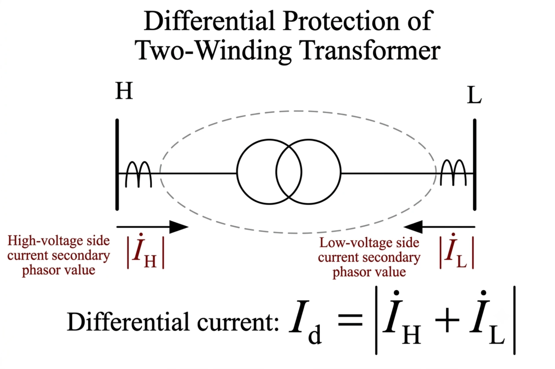
Transformer Fault Types: Causes, Symptoms and Protection Methods
Transformer fault types refer to the electrical, thermal, mechanical and insulation faults that can occur inside a transformer or in its external connections during operation. Common transformer faults include winding short circuits, inter-turn faults, earth faults, bushing faults, core faults, overheating, overexcitation and external short circuits. If these faults are not detected and cleared quickly, they can cause insulation damage, winding overheating, transformer fires, equipment failure and extended power outages.
Understanding the different types of transformer faults is essential for designing an effective transformer protection scheme. Different faults require different detection and protection methods, such as transformer differential protection, overcurrent protection, earth fault protection, Buchholz protection, thermal protection and overexcitation protection.
This guide explains the main transformer fault types, their causes, typical symptoms, consequences and corresponding protection methods, helping engineers and project teams select an appropriate transformer protection scheme for power transformers and distribution transformers.
What Are Transformer Faults?
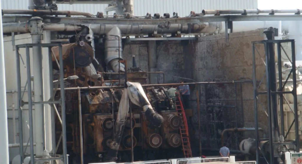
A transformer fault is any abnormal condition or failure that occurs within the transformer itself or in its immediate connecting system, which deviates from normal operating parameters and may compromise the transformer’s integrity, performance, or safety.
Transformer failure modes split into two groups with different protection answers. A fault that arrives suddenly, such as a bushing flashover or a winding short circuit, has to be cleared in cycles by a relay. A fault that builds slowly, such as insulation aging or core degradation, only becomes visible in oil gas or temperature trends, and it needs monitoring rather than a trip setting.
Transformer faults can be electrical (short circuits, insulation breakdown), thermal (overheating, hot spots), mechanical (winding deformation, core movement), or chemical (oil degradation, gas generation). Faults may develop suddenly due to external events (lightning strikes, system faults) or gradually over time due to aging, stress accumulation, or environmental factors. Early detection and prompt clearing of faults are critical to minimize damage and prevent secondary failures.
Main Types of Transformer Faults
Transformer faults are broadly classified into three categories based on their origin and location:
- Internal Transformer Faults: Occur within the transformer tank, involving the core, windings, insulation, bushings, or internal connections. These are the most severe and require fast clearing.
- External Transformer Faults: Occur outside the transformer tank but on the connected power system, such as faults on busbars, feeders, or adjacent equipment. While the transformer is not the source, it must withstand and clear these through-faults without damage.
- Abnormal Operating Conditions: Not immediate faults but prolonged operating states outside design parameters (e.g., overload, overexcitation, low oil level) that can lead to faults if not corrected.
Internal Transformer Faults
Internal transformer fault types are the ones that damage the active parts, so they get the fast, selective functions rather than long time delays. Internal faults are the most critical because they involve the active parts of the transformer and can release large amounts of energy, causing rapid pressure buildup and oil decomposition.
Winding Inter-Turn Faults
What it is: A short circuit between adjacent turns within the same winding layer.
Cause: Insulation breakdown between turns due to aging, thermal stress, or manufacturing defects. Voltage spikes (lightning or switching surges) can also puncture turn-to-turn insulation.
Why it’s dangerous: Even a single shorted turn creates a local circulating current that generates intense heat at the fault point. This rapidly develops into a severe fault, often escalating to phase-to-earth or phase-to-phase faults.
Detection: Inter-turn faults produce small current imbalances initially, making them difficult to detect with simple overcurrent relays. Differential protection (87T) with high sensitivity is the primary method, as it detects the unbalance between input and output currents.
Phase-to-Phase Faults
What it is: A short circuit between two different phase windings (e.g., A-B or B-C).
Cause: Often results from insulation failure that allows arcing between phases, or from severe winding deformation during external fault events. Can also originate from an inter-turn fault that escalates.
Why it’s dangerous: Phase-to-phase faults involve extremely high fault currents (can be 10–20 times rated current). They generate massive electromagnetic forces that can permanently deform windings and destroy the core.
Detection: Easily detected by differential protection (87T) , instantaneous overcurrent (50) , and overcurrent (51) relays. Fast clearing is essential to limit mechanical damage.
Winding-to-Earth Faults
What it is: A short circuit between one phase winding and the transformer core/tank (earth/ground).
Cause: Insulation failure to ground, often due to moisture ingress, aging, or mechanical damage. In solidly grounded systems, these faults produce high currents; in impedance-grounded systems, fault currents may be limited.
Why it’s dangerous: Energizes the transformer tank, creating a safety hazard. May cause core damage, oil decomposition, and tank rupture if not cleared quickly.
Detection: Earth fault relays (50N/51N) are the primary protection. Differential protection (87T) also detects this as an unbalance. In resistance-grounded systems, sensitive 51N settings are required.
Core Faults
What it is: Localized heating or short circuits within the transformer core laminations.
Cause: Loose core bolts, damaged insulation between laminations, or core grounding issues (multiple ground points causing circulating currents). Core faults often develop gradually.
Why it’s dangerous: Creates hot spots that degrade insulation and oil, eventually leading to winding faults. Core fault energy is typically low but persistent.
Detection: Buchholz relay (63) alarms on gas accumulation from oil decomposition. Dissolved Gas Analysis (DGA) detects elevated ethylene and hydrogen. Thermal monitoring may show localized temperature rises.
Bushing Faults
What it is: Failure of the insulating bushing that carries current through the transformer tank wall.
Cause: Moisture ingress, contamination, cracking due to thermal cycling, or electrical stress. Bushing failures are often progressive, starting with partial discharges.
Why it’s dangerous: A bushing flashover can cause a phase-to-earth or phase-to-phase fault at the transformer terminal, potentially exploding and causing fire.
Detection: Differential protection (87T) and overcurrent (50/51) will detect the resulting short circuit. Bushing-specific sensors (capacitance and power factor monitoring) can provide early warning but are not standard relay functions.
Lead and Connection Faults
What it is: Failure at internal or external connections, such as lead wires, tap changer connections, or terminal lugs.
Cause: Loose connections, oxidation, thermal expansion/contraction cycles, or manufacturing defects. Poor connections generate heat and lead to arcing.
Why it’s dangerous: Can cause localized overheating, oil decomposition, and eventually escalate into winding faults.
Detection: Buchholz relay detects gas from arcing. Temperature monitoring may show abnormal hot spots. DGA detects acetylene (from arcing).
External Transformer Faults
External fault types are the ones that do not damage the transformer directly but still stress it, because fault current flows through the winding on its way to the fault. External faults occur outside the transformer zone but still affect the transformer because fault current flows through it. The transformer must withstand these through-faults without damage, and protection must coordinate to clear the fault while keeping the transformer in service.
External Phase-to-Phase Short Circuits
A phase-to-phase fault on a downstream feeder, busbar, or adjacent line. High fault current flows through the transformer to feed the fault. The transformer experiences severe mechanical stresses. Overcurrent protection downstream should operate first; transformer overcurrent (51) acts as backup with time coordination.
External Earth Faults
A ground fault on the system downstream of the transformer. The magnitude depends on system grounding. In solidly grounded systems, current can be high. The transformer must handle the zero-sequence current without core saturation or overheating. Earth fault relays (51N/50N) on the downstream side clear first; transformer provides backup.
Busbar and Feeder Faults
Faults occurring on the switchgear busbars or outgoing feeders directly connected to the transformer. Protection coordination is critical to ensure the feeder/busbar protection operates before the transformer backup protection. Transformer differential (87T) must remain stable (not operate) during these external faults to avoid unnecessary tripping.
Common Transformer Abnormal Operating Conditions
These are not instantaneous faults but prolonged deviations from normal operating conditions. If left uncorrected, they degrade insulation and lead to actual faults.
Transformer Overload
What it is: Sustained current exceeding the transformer’s rated capacity.
Effect: Windings overheat, accelerating insulation aging (the 6°C rule: every 6°C rise halves insulation life). Overload can be acceptable for short periods (emergency loading) but not continuously.
Protection: Thermal overload relay (49) models winding hot-spot temperature and provides alarm and trip stages. Cooling system monitoring also supports overload management.
Transformer Overheating
What it is: Excessive temperature in windings, core, or oil beyond design limits.
Effect: Accelerated insulation degradation, oil decomposition, and reduced mechanical strength. Overheating often results from overload, cooling failure, or internal hot spots.
Protection: Temperature monitoring (WTI/Oil temperature) via RTD inputs. Thermal relay (49) provides model-based protection. Cooling system controls should maintain acceptable temperatures.
Overexcitation
What it is: High Volts/Hertz (V/Hz) ratio causing core flux density to exceed design limits.
Effect: Core saturation, leading to excessive magnetizing current, severe heating, and vibration. Overexcitation typically occurs during system overvoltage or underfrequency events.
Protection: Overexcitation relay (24) monitors V/Hz ratio and trips or alarms based on a time curve. Mandatory for generator step-up transformers.
Low Oil Level
What it is: Oil level drops below the minimum safe level in the conservator or main tank.
Effect: Exposes windings to air, reducing dielectric strength and increasing the risk of insulation failure. Also compromises cooling.
Protection: Buchholz relay (63) includes an oil level alarm contact. Oil level gauges with low-level alarming are also used.
Cooling System Failure
What it is: Loss of cooling (pumps, fans, or radiator banks) resulting in reduced heat dissipation.
Effect: Rapid temperature rise, even under normal load, leading to overload-like thermal stress and potential transformer failure.
Protection: Cooling control relays monitor pump/fan running status and initiate alarms. Thermal relay (49) trips if temperature rises above safe limits.
Overvoltage and Undervoltage
Overvoltage (59): Sustained high voltage stresses winding insulation; may cause corona, partial discharge, and eventual breakdown.
Undervoltage (27): Results in increased current for same load, causing overheating; also used for load shedding and auto-transfer schemes.
Protection: Overvoltage relay (59) and Undervoltage relay (27) monitor bus voltage and provide alarms or trip signals as required.
Transformer Fault Causes
Understanding the root causes of transformer faults enables proactive maintenance and better protection design.
Insulation Aging
What it is: Gradual deterioration of paper, pressboard, and oil insulation over time. Insulation life halves for every 6°C increase in operating temperature (Arrhenius law). Moisture and oxygen accelerate the aging process.
Prevention: Thermal monitoring, DGA tracking, and periodic insulation testing (power factor, capacitance) are essential. Avoid prolonged overloads.
Thermal Stress
What it is: Damage caused by high temperatures from overloads, cooling failures, or internal hot spots. Thermal stress causes insulation embrittlement, paper carbonization, and oil sludge formation. Repeated thermal cycling also causes mechanical expansion/contraction that loosens connections.
Prevention: Proper thermal overload protection (49), cooling system maintenance, and load management.
Electrical Stress
What it is: Stress from overvoltages, lightning strikes, switching surges, or system faults. Electrical stress can puncture solid insulation, create tracking paths, and initiate partial discharges. Even if no immediate failure occurs, each event causes cumulative insulation damage.
Prevention: Surge arresters, proper grounding, and voltage protection (59). Good protection coordination minimizes the duration of through-faults.
Mechanical Damage
What it is: Physical distortion of windings and core due to electromagnetic forces during external short circuits. Even if the winding does not fail immediately, repeated mechanical shocks loosen bracing and gradually degrade structural integrity. This is a leading cause of delayed winding failures.
Prevention: Fast fault clearing by downstream protection minimizes mechanical stress. Proper through-fault withstand capability should be specified at procurement.
Moisture and Contamination
What it is: Water ingress and contamination of oil with particles or degradation products. Moisture dramatically reduces dielectric strength and accelerates aging. Contaminants can create conductive paths and initiate tracking.
Prevention: Sealed conservator systems, silica gel breathers, and routine oil testing (water content, dielectric breakdown voltage). DGA monitors for moisture-related partial discharges.
Manufacturing and Installation Problems
What it is: Defects introduced during factory production or site installation, such as loose connections, inadequate drying, or improper torque on bolted joints. These often manifest early in transformer life. Poor transport handling can also cause internal damage.
Prevention: Factory acceptance tests (FAT), site commissioning tests (SAT), and thorough inspection during installation. Relay testing during commissioning ensures protection is correctly set.
Transformer Fault Symptoms
Transformer fault causes and symptoms arrive as matched pairs, so a symptom usually points back to one root cause. The early ones are most often audible noise, oil temperature rise, a Buchholz gas alarm or an abnormal DGA trend. The table below pairs each symptom with the fault behind it.
| Symptom | Possible Fault |
|---|---|
| Abnormal noise (buzzing/humming) | Core loose, overexcitation, winding movement. |
| Excessive oil temperature rise | Overload, cooling failure, internal hot spot. |
| Buchholz gas alarm | Incipient fault (arcing, overheating, low oil). |
| Low oil level alarm | Leak or conservator issue. |
| Abnormal DGA gas levels | Decomposition indicates specific fault types. |
| Bushing discoloration/cracking | Bushing deterioration, partial discharge. |
| Sudden pressure relief valve operation | Severe internal fault (major short circuit). |
| Winding resistance imbalance | Internal connection issue or turn fault. |
Which Detection Method Matches Which Transformer Fault Type?
Transformer protection methods fall into four groups, each covering a slice of the transformer fault types the others cannot reach: differential (87T), overcurrent and earth fault (50, 51, 51N), non-electrical functions such as 63, 49 and 24, and condition monitoring by DGA and temperature. A scheme built on one group alone leaves gaps, which is why the table below pairs every fault type with the function that clears it.
Electrical Protection
Electrical protection relays monitor currents, voltages, frequency, and derived quantities. They provide the fastest response (typically < 2–3 cycles for differential protection). Key electrical protections include differential, overcurrent, earth fault, voltage, and overexcitation relays. These are the primary means of clearing electrical faults.
Differential Protection
The differential element, ANSI 87T, is the one that sees a winding fault while the fault is still inside the transformer zone.
Principle: Compares currents entering and leaving the transformer. Under normal conditions, these are equal (minus magnetizing current). Under internal fault, the difference exceeds the threshold and trips instantly.
Key features: Harmonic restraint (2nd harmonic for inrush, 5th harmonic for overexcitation), slope/restraint characteristic to prevent through-fault misoperation.
Overcurrent and Earth Fault Protection
Overcurrent (50/51): Provides backup protection for phase faults. Instantaneous (50) clears severe faults; time-delayed (51) coordinates with downstream devices.
Earth Fault (50N/51N): Detects ground faults. 50N for high-magnitude ground faults; 51N for sensitive detection of low-magnitude ground faults.
Buchholz and Gas Protection
Buchholz relay (63): Mechanical relay installed in the oil pipe between main tank and conservator. Responds to:
- Gas accumulation (alarm): Slow gas buildup from incipient faults.
- Oil surge (trip): Rapid oil movement from severe faults.
Pressure relief devices: Operate on sudden pressure rise in the tank, providing a backup mechanical trip.
Temperature Monitoring
- Winding Temperature Indicator (WTI): Measures or calculates hot-spot temperature.
- Oil Temperature Indicator (OTI): Measures top oil temperature.
- RTD sensors (PT100) connect directly to relay inputs for alarm and trip functions. Thermal relay (49) uses these inputs with thermal modeling.
Dissolved Gas Analysis
What it is: Laboratory or online analysis of gases dissolved in transformer oil.
Key gases and their causes:
- Hydrogen (H₂): Corona, partial discharge, or low-temperature overheating.
- Methane (CH₄), Ethane (C₂H₆), Ethylene (C₂H₄): Thermal decomposition at various temperatures.
- Acetylene (C₂H₂): High-energy arcing (severe fault).
- Carbon Monoxide (CO), Carbon Dioxide (CO₂): Cellulose insulation decomposition.
Method: IEC 60599 / IEEE C57.104 standards use gas ratios to diagnose fault types. Online DGA monitors provide continuous trending.
Transformer Fault Types and Protection Methods
This is the table to copy into a specification sheet. Each transformer fault type listed above maps to at least one ANSI function, and several transformer fault types need two.
| Fault type | ANSI device | Primary relay function | Backup / supporting function | Signal the relay sees |
|---|---|---|---|---|
| Inter-turn (turn-to-turn) fault | 87T | Differential, sensitivity set high, restraint slope 30% or less | 51, time-delayed | Differential current, plus DGA trend |
| Phase-to-phase fault | 87T | Differential, instantaneous operation | 50 / 51 | Differential current |
| Winding-to-earth fault | 87T / 51N | Differential plus sensitive earth fault | 51 | Differential current, zero-sequence current |
| Core (lamination) fault | 63 | Buchholz gas alarm, alarm only, no trip | 49 thermal model | Gas accumulation, DGA methane and hydrogen |
| Bushing fault | 87T / 50 | Differential on the resulting phase short | 51 | Differential current, bushing capacitance trend |
| Lead or tap changer connection fault | 63 / 49 | Buchholz gas alarm and thermal trip | No separate backup | Acetylene in DGA, gas accumulation |
| External phase-to-phase short circuit | 51 | Downstream primary, transformer 51 as backup | 51 | Through-fault current in the coordination study |
| External earth fault | 51N | Downstream earth relay primary, transformer 51N backup | 51N | Zero-sequence current |
| Overload | 49 | Thermal replica of winding hot-spot temperature | Cooling control alarm | Winding temperature from RTD or WTI |
| Overheating | 49 | Thermal trip stage above the limit | Cooling control | Winding and oil temperature |
| Overexcitation | 24 | V/Hz trip or alarm on a time curve | 59 | Bus voltage and frequency |
| Low oil level | 63 | Oil-level alarm contact in the Buchholz | No separate backup | Conservator oil level |
| Cooling system failure | 49 | Thermal trip when temperature exceeds the limit | Cooling control alarm | Oil and winding temperature |
| Overvoltage / undervoltage | 59 / 27 | Voltage alarm or trip | 24 | Bus voltage |
Read the mapping as the fault-to-function checklist for a specification. Power transformer protection groups the same ANSI functions by voltage class and rating, and transformer differential protection working principle covers the restraint slope behind the 87T rows.
Transformer Fault Protection by Transformer Type
Different transformer types require different protection emphases based on their size, criticality, and application. Protection emphasis follows the transformer fault types that actually hurt at that voltage class, which is why the four cases below diverge so much.
Distribution Transformers
- Rating: Typically < 5 MVA.
- Protection: Fuses or reclosers with overcurrent (51/51N) are common. Differential (87T) is usually cost-prohibitive. Thermal (49) and temperature alarms are recommended.
- Fault focus: Overload, external faults, and basic internal faults.
Power Transformers
- Rating: > 10 MVA, substation-level.
- Protection: Full suite including 87T (primary), 51/51N (backup), 49 (thermal), 24 (overexcitation if needed), and 63 (Buchholz). Voltage protection (27/59) may also be applied.
- Fault focus: All internal fault types, plus backup for external faults.
Step-Up Transformers (GSU)
A generator step-up transformer is faulted and grounded differently from a substation transformer: the LV side is generator-grounded and the fault level comes from the machine. The step-up transformer protection scheme covers that arrangement.
- Location: Between generator and transmission grid.
- Protection: Requires high-speed 87T with TPY CTs to handle CT saturation. 24 (V/Hz) is mandatory due to generator startup/shutdown. Must include sudden pressure relay (63) and overexcitation protection.
- Fault focus: Overexcitation, generator-side faults, and high-fault-current internal faults.
Two-Winding Transformers
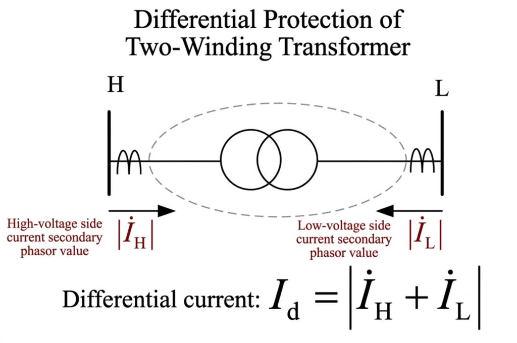
- Most common type.
- Protection: Simple differential zone with one set of CTs per side. Standard 87T + 51/51N + 49 + 63 applies.
- Fault focus: All internal and through-fault scenarios.
Two-winding transformers take the simplest arrangement: one differential zone with one set of CTs per side, plus 51/51N, 49 and 63. Our 87T transformer protection relay page lists the CT and input options for that case.
Three-Winding Transformers
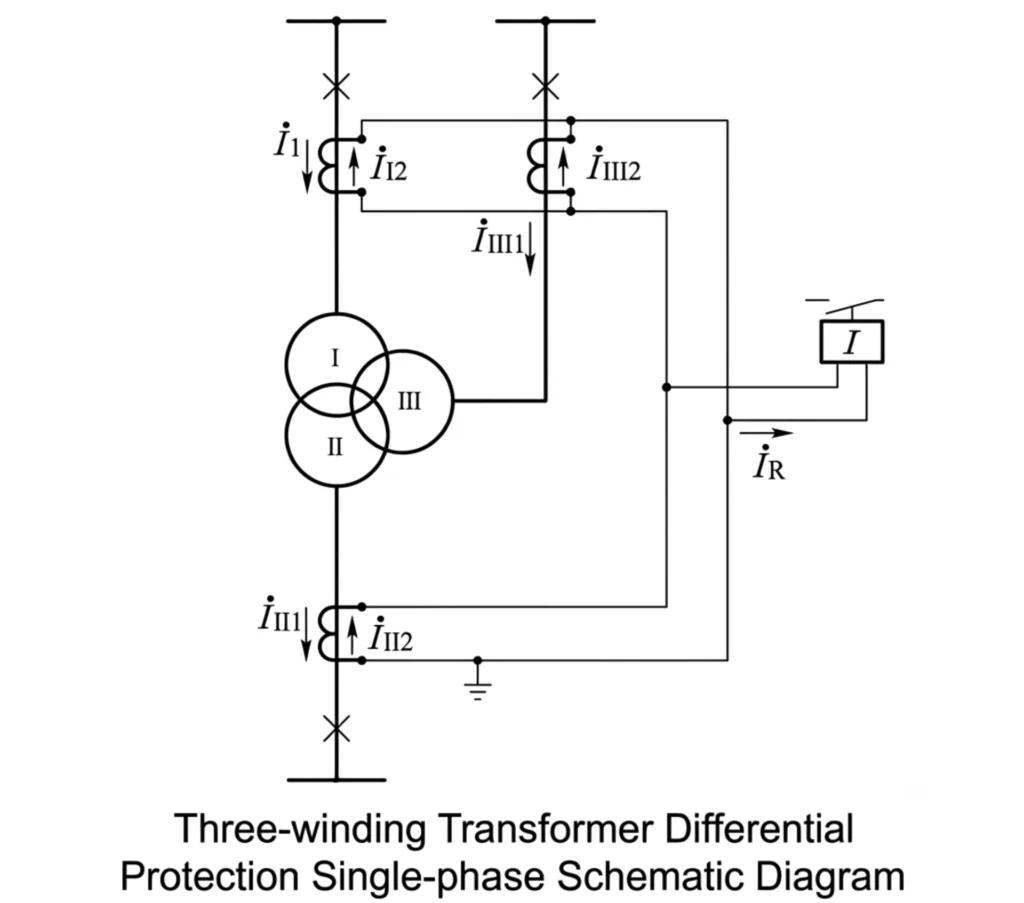
- Used for tertiary connections (e.g., capacitor banks, auxiliary loads, or to provide a third voltage level).
- Protection: 87T must have three restraint inputs (one per winding). Requires careful CT ratio matching and compensation for phase shifts between each winding. Backup overcurrent may be required on each winding separately.
- Fault focus: Same as power transformers, with added complexity for multi-winding coordination.
Three-winding units need a differential element with three restraint inputs, one per winding, and a separate backup overcurrent on each winding. Our 87T three-winding protection relay page covers the extra CT matching that adds.
How to Prevent Transformer Faults
While protection relays minimize fault damage, prevention is always preferable. The steps below attack transformer fault types at their source: insulation, cooling, connections, monitoring and coordination.
1. Proper Specification and Selection
- Choose transformers with adequate short-circuit withstand capability, proper insulation class, and appropriate cooling.
- Specify correct CT parameters (class, ratio, burden) and relay functions for the application.
Stage 1 is the transformer itself, and the rating, vector group and short-circuit duty decide everything downstream. Transformer protection relay selection walks through that workflow.
2. Regular Condition Monitoring
- Perform routine DGA to track gas trends and identify incipient faults early.
- Monitor temperatures (WTI, OTI) and cooling system performance continuously.
- Inspect bushings, oil level, and pressure relief devices regularly.
- Test winding resistance and insulation power factor periodically.
3. Scheduled Maintenance
- Follow manufacturer-recommended maintenance intervals.
- Replace degraded oil, check oil quality (breakdown voltage, water content), and clean breathers.
- Check and re-torque electrical connections.
- Test protection relay settings and CT circuits during outages.
4. Protection Relay Testing and Coordination
- Ensure protection relays are properly set and coordinated with upstream/downstream devices.
- Periodically perform primary and secondary injection tests to verify relay response.
- Update relay settings when system changes occur.
5. Operational Best Practices
- Avoid prolonged overloads.
- Ensure proper cooling is available before loading the transformer.
- Limit the number of through-fault exposures (monitor and reduce if excessive).
- Follow proper energization procedures to minimize inrush stress.
Transformer fault types and the functions that clear them are the two halves of a protection schedule. For a project-specific application, work through the fault-to-function table against the transformer data sheet, then confirm CT ratios and settings in a full coordination study.
Technical References
Device numbers used in the tables above follow ANSI/IEEE C37.2 and the transformer protection guide.
| Source | What it covers | Type | Edition |
|---|---|---|---|
| IEEE C37.91 | Application guide for protective relaying of power transformers, including differential and backup functions | Standard | 2021 |
| IEC 60255-187-1:2021 | Functional requirements for differential protection of generators, motors and transformers | Standard | 2021 |
| ANSI/IEEE C37.2-2022 | Device function numbers: 87T, 50, 51, 51N, 49, 24, 63, 59, 27 | Standard | 2022 |
| IEC 61869-2:2012 | Current transformer requirements for protection duty, including accuracy limits | Standard | 2012 |
| IEC 60255-1:2022 | General requirements and testing for measuring and protection relays | Standard | 2022 |
| IEEE C37.110-2023 | Application of current transformers for protective relaying, including saturation and TPY cores | Standard | 2023 |
Transformer Faults FAQ (Concise)
What are the main types of transformer faults?
Three categories: Internal faults (windings, core, bushings), external faults (downstream system faults), and abnormal operating conditions (overload, overexcitation, cooling failure). Those three groups account for nearly every transformer fault type, and on a project they cover the ones listed in the data sheet.
What is the most common transformer fault?
Of all transformer fault types, winding inter-turn faults are the commonest: insulation breakdown between adjacent turns, often caused by aging, thermal stress, or moisture. They start small but can escalate rapidly.
What is an internal transformer fault?
A fault inside the tank involving windings, core, bushings, or connections (e.g., phase-to-phase, winding-to-earth, inter-turn faults). Most severe, and it requires fast clearing via differential protection (87T).
What is an external transformer fault?
A fault outside the tank on connected feeders, busbars, or lines. Fault current flows through the transformer. Downstream protection should clear first; transformer overcurrent relays act as backup.
What causes transformer winding faults?
Main causes: Insulation aging, thermal stress (overload), electrical stress (surges), mechanical damage (short-circuit forces), moisture/contamination, and manufacturing defects.
What causes transformer earth faults?
Causes: Insulation breakdown to ground, bushing flashover, core faults, loose connections touching the tank, or oil contamination reducing dielectric strength.
How are transformer faults detected?
Four methods: Electrical relays (87T, 50/51, 51N), mechanical devices (Buchholz, pressure relief), temperature monitoring (RTDs, 49 thermal relay), and Dissolved Gas Analysis (DGA) for incipient faults.
Which protection is used for transformer internal faults?
Primary: Differential protection (87T). Supplemental: Buchholz (63) for gas, earth fault (50N/51N), overcurrent (50/51), and thermal (49). Backup: Time-delayed overcurrent (51).
What protection is used for transformer external faults?
Downstream protection clears first. Transformer provides backup overcurrent (51/51N) with time coordination. Differential (87T) must remain stable during through-faults.
Can a transformer differential relay detect all transformer faults?
No. 87T detects most winding faults but cannot detect incipient faults (gas), high-impedance earth faults, very minor turn faults, or thermal issues. Use Buchholz, DGA, 51N, and 49 to cover these gaps.
What is the difference between a transformer fault and an abnormal operating condition?
| Aspect | Transformer fault | Abnormal operating condition |
|---|---|---|
| Damage at the fault location | Immediate damage occurs. | Deviation from normal, no damage yet. |
| Relay action required | Requires instant trip. | Requires alarm plus corrective action. |
| Typical examples | Short circuit, bushing flashover. | Overload, cooling failure, low oil. |
How can transformer faults be prevented?
Five pillars: Proper specification (CTs, relays), regular monitoring (DGA, temperature), scheduled maintenance (oil, connections), relay testing/coordination, and operational best practices (avoid overloads, ensure cooling).



About Author

Hello, I'm Leno Zhang. I have 15 years of experience in the power relay protection industry with extensive pre-sales and after-sales project experience. Our company specializes in various complete sets of relay protection and automation equipment. I can assist customers in solving all practical on-site project challenges and provide optimal integrated solutions.
Tell Us Your Requirement
High Quality
Stable performance, reliable design, ensuring safe operation for power system protection and grid stability.
Fast Delivery
Timely delivery to support your urgent orders and project schedules efficiently and professionally at any time.
Best Warranty
Professional Warranty: Reliable after-sales support for stable relay protection and long-term customer satisfaction.