

-
Leon Zhang sales consultant
-
Email: zxl635973785@gmail.com
-
Phone/WhatsApp: +86 13655813266
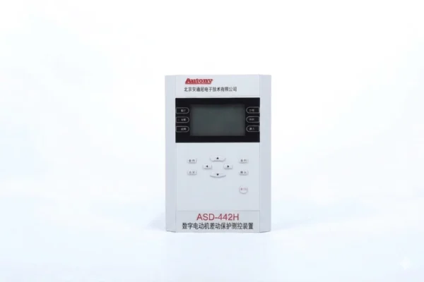
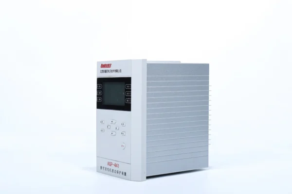
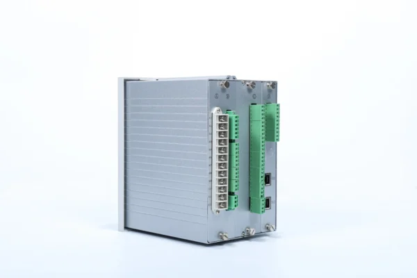
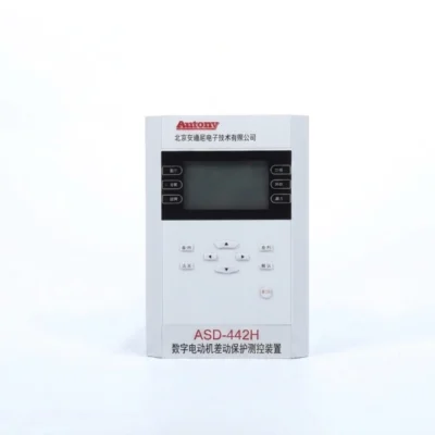
Motor Differential Protection Relay | ANSI 87M
Overview
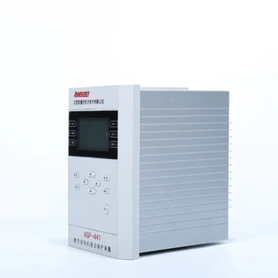
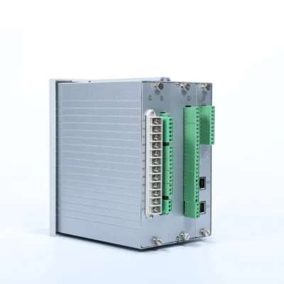
The motor differential protection device adopts professional differential motor protection logic. It is an integrated protection and control unit developed for high- and low-voltage asynchronous motors, available for standalone panel installation or built-in mounting in switchgear cabinets.
Product Functions (ANSI)
87/87M/50/51/49/48/46/50N/59/59N/27/81O/81U/60
Communication Mode
Optional: RS-485, CAN bus, Ethernet, IEC 60870-5-103 (IEC-103), IEC 61850
Send your requirements, we will quote for you within 12 hours
Description
Overview
The Motor Differential Protection Relay is a numerical protection device designed for internal fault protection of medium- and high-voltage motors. It uses ANSI 87M percentage-bias differential protection to compare currents at the motor line and neutral ends, providing fast and sensitive protection against internal stator faults.
The relay also integrates overcurrent, overload, locked-rotor, negative-sequence, earth-fault, voltage and frequency protection functions for complete motor protection and backup protection.
What Is Motor Differential Protection?
Motor differential protection is a primary protection scheme used to detect internal faults within a motor stator winding. The relay compares the current entering and leaving the protected motor zone. Under normal operation and external faults, the currents are substantially balanced. When an internal fault occurs, the resulting differential current exceeds the protection threshold and the relay issues a trip command.
ANSI 87M is the standard protection function designation commonly used for motor differential protection.
ANSI 87M Motor Differential Protection
ANSI 87M identifies differential protection for motors. The function compares the currents at the two ends of the motor stator winding and operates when the differential current exceeds the configured threshold while satisfying the restraint conditions.
| Parameter | Description |
|---|---|
| ANSI Code | 87M |
| Protection Type | Motor Differential Protection |
| Protected Zone | Motor Stator |
| Main Function | Internal Fault Protection |
| Typical Application | Medium- and High-Voltage Motors |
| Operating Principle | Differential Current + Bias/Restraint |
| Main CT Arrangement | Line-Side + Neutral-Side CTs |
How Does Motor Differential Protection Work?
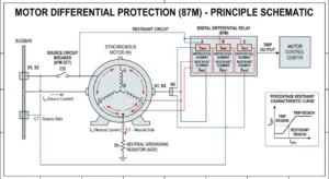
Motor differential protection compares currents entering and leaving the motor. An internal fault creates a differential current that triggers the trip.
Step 1: Current Measurement
CTs measure three-phase currents at both the line and neutral ends of the motor.
Step 2: Differential Current Calculation
The relay compares the corresponding phase currents and calculates the differential current (I_diff). Under normal conditions, I_diff ≈ 0. Under internal faults, I_diff > 0.
Step 3: Differential Protection Trip
When I_diff exceeds the set threshold, the relay trips to isolate the motor.
Percentage Bias / Restraint Characteristic
To prevent false tripping during external faults or CT saturation, the relay uses a bias characteristic:
I_diff > k × I_bias + I_diff0
Where:
-
I_bias = average or maximum of the two end currents
-
k = bias slope (typically 20–40%)
-
I_diff0 = minimum pick-up threshold
Dual-slope bias is often used to match different CT characteristics and system conditions.
Key Benefits:
-
Security – avoids maloperation during external faults
-
Sensitivity – detects internal faults accurately
-
Stability – reliable across various fault levels
Principle of Motor Differential Protection
Percentage-Bias Differential Protection
Percentage-bias differential protection improves stability during motor starting and external faults by increasing the operating threshold in proportion to the restraint current.
Why is bias required?
-
CT saturation – High through-currents distort CT outputs, creating false differential signals.
-
External short circuits – Heavy fault currents cause measurement discrepancies between CTs.
-
CT mismatch – Different ratios, classes, or excitation characteristics introduce inherent errors.
-
Motor starting transients – High inrush currents and DC offset affect CT accuracy.
-
Measurement errors – Input circuit tolerances and sampling inaccuracies add small errors.
By using through-current as a restraint, the relay sets a variable threshold – high during external faults for stability, low during internal faults for sensitivity.
This helps prevent unwanted operation while maintaining sensitivity to internal motor faults.
Value for engineers:
-
Balances security and sensitivity
-
Prevents nuisance tripping and costly shutdowns
-
Guides proper CT selection
-
Simplifies commissioning and troubleshooting
CT Configuration for Motor Differential Protection
Proper CT configuration is critical for reliable 87M protection. Any mismatch in phase, polarity, or ratio creates false differential signals and may cause nuisance tripping.
Line-Side CTs – Installed at the motor feeder side, measuring current entering the motor.
Neutral-Side CTs – Installed at the motor neutral end, measuring current leaving the motor.
Phase Matching – The relay must compare the same phases (A–A, B–B, C–C) between line and neutral sides.
CT Polarity – CTs are connected in opposition (subtractive polarity) to ensure differential current appears only during internal faults. Reversed polarity causes false tripping under normal load.
CT Ratio – Ratios must be identical or properly compensated. Ratio mismatch creates standing differential error.
Secondary Wiring – Must be correctly routed and terminated. Wiring errors are a common commissioning issue.
Conventional vs Self-Balancing Motor Differential Protection
| Feature | Conventional 87M | Self-Balancing 87M |
|---|---|---|
| Protection Principle | Current differential comparison | Magnetic balance |
| CT Arrangement | Line-side + neutral-side CTs | Balanced CT arrangement |
| Secondary Wiring | More extensive | Reduced for compatible schemes |
| Main Application | Conventional motor differential schemes | Motors designed for self-balancing schemes |
| Product Page | This page | Self-Balancing 87M page |
Motor Differential Protection Functions
Primary Protection
87M Percentage-Bias Differential Protection
87 Differential Instantaneous Protection
Current Protection
- 50 Instantaneous Overcurrent
- 51 Time Overcurrent
- 46 Negative Sequence
- 50N/51N Zero Sequence
Motor Thermal and Starting Protection
- 49 Thermal Overload
- 48 Locked Rotor
- Long Start Protection
- Motor Start Blocking
Voltage and Frequency Protection
- 27 Undervoltage
- 59 Overvoltage
- 59N Zero Sequence Overvoltage
- 81U Underfrequency
- 81O Overfrequency
Supervision
- 60 PT Circuit Supervision
- Control Circuit Supervision
- Non-Electrical Protection
Applications of Motor Differential Protection
Motor differential protection is commonly applied to medium- and high-voltage motors, particularly large or critical motors where fast and sensitive internal fault protection is required.
Typical Applications
- Large MV motors
- High-voltage industrial motors
- Mine ventilation motors
- Pump motors
- Compressor motors
- Fan motors
- Critical process motors
- Power plant auxiliary motors
What Faults Does 87M Motor Differential Protection Detect?
| Fault | 87M |
|---|---|
| Stator Phase-to-Phase Fault | ✓ |
| Internal Stator Earth Fault | ✓* |
| Turn-to-Turn Fault | Depends on fault location and scheme |
| External Short Circuit | Stable / restrained |
| Motor Overload | Use 49/51 |
| Rotor Mechanical Fault | Not directly |
| Bearing Failure | Not directly |
| Low-Level High-Resistance Ground Fault | May require dedicated ground-fault protection |
Motor Differential Protection vs Overcurrent Protection
| Item | 87M Differential | 50/51 Overcurrent |
|---|---|---|
| Main Purpose | Internal motor faults | Overcurrent / backup |
| Protection Zone | Defined motor zone | Broader system zone |
| Speed | Fast | Usually delayed |
| Internal Stator Fault | High sensitivity | Depends on fault current |
| External Fault | Restrained / stable | Backup |
| CT Arrangement | Two-end comparison | Usually line-side |
| Typical Role | Main protection | Backup protection |
Motor Protection Relay Communication and SCADA Integration
| Interface | Protocol |
|---|---|
| Ethernet | IEC 61850 |
| Ethernet | IEC 60870-5-103 |
| RS-485 | Modbus RTU |
| Time Synchronization | SNTP / IRIG-B |
Key Motor Differential Protection Settings
| Setting | Purpose |
|---|---|
| Differential Starting Current | Minimum differential current for operation |
| Differential Instantaneous Setting | Fast high-current fault protection |
| Inflection Point | Defines bias characteristic transition |
| Percentage Bias Coefficient | Provides differential protection restraint |
| Motor Rated Current | Base current for protection calculations |
| Motor Starting Time | Coordinates protection during motor startup |
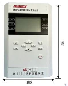
Outline and Installation Dimensions
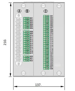
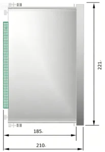
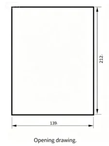
FAQ
Q1. What is motor differential protection?
A protection scheme that compares currents entering and leaving the motor. Any difference indicates an internal fault, triggering a trip to prevent motor damage.
Q2. What is ANSI 87M?
ANSI device number 87M designates motor differential protection. It detects internal stator winding faults by comparing current at both ends of the protected zone.
Q3. How does motor differential protection work?
CTs measure currents at the line and neutral ends. The relay calculates the differential current (I_diff). Under normal conditions, I_diff ≈ 0. An internal fault creates I_diff > 0, which triggers the trip.
Q4. What motors require differential protection?
Typically medium to large three-phase AC motors (typically ≥ 1,000 kW / ≥ 4 kV), critical motors in industrial plants, mines, oil & gas, pumping stations, and any motor with high replacement cost or severe production impact.
Q5. What faults can 87M detect?
Internal stator winding faults including phase-to-phase faults, turn-to-turn short circuits, and ground faults within the protected zone.
Q6. What CT configuration is required?
One set of CTs on the line side and one set on the neutral side. The line-side and neutral-side CTs must be matched in phase sequence, polarity, and ratio.
Q7. Why are line-side and neutral-side CTs required?
They define the differential protection zone. The relay compares the currents from both ends – any difference between them indicates a fault within the motor, while external faults or through-currents remain balanced.
Q8. What is percentage-bias differential protection?
A scheme that increases the operating threshold proportionally with the restraint (through) current. This provides stability during external faults or motor starting while maintaining sensitivity for internal faults.
Q9. Can 87M operate during motor starting?
Yes, but with bias settings to prevent false tripping due to starting transients. The bias characteristic keeps the relay secure during high inrush currents.
Q10. How is 87M coordinated with overcurrent protection?
87M provides primary protection for internal faults (fast, high-sensitivity). Overcurrent protection (ANSI 50/51) serves as backup for faults outside the differential zone or if 87M fails to clear the fault.
Q11. What are the key 87M protection settings?
Key settings include: minimum pick-up current (I_diff0), bias slope (single or dual-slope), restraint current calculation method, and trip time delay.
Q12. What tests are required before commissioning?
CT polarity verification, primary injection testing, phase rotation check, ratio verification, secondary loop continuity test, relay differential current reading under load, and trip logic testing.
Q13. What is the difference between motor and transformer differential protection?
Motor differential protection typically uses one set of CTs at each end (line and neutral). Transformer differential protection requires additional compensation for transformer ratio, vector group, and tap changes.
Q14. What is the difference between conventional and self-balancing motor differential protection?
Conventional protection requires multiple CTs per phase with complex wiring. Self-balancing uses one balanced window CT per phase, reducing CT count and secondary wiring while maintaining reliable detection.
Q15. Can the relay communicate with SCADA?
Yes. It supports communication protocols such as Modbus RTU and IEC 61850 (GOOSE and MMS) for remote monitoring and control.
2 reviews for Motor Differential Protection Relay | ANSI 87M
Related products
High Quality
Stable performance, reliable design, ensuring safe operation for power system protection and grid stability.
Fast Delivery
Timely delivery to support your urgent orders and project schedules efficiently and professionally at any time.
Best Warranty
Professional Warranty: Reliable after-sales support for stable relay protection and long-term customer satisfaction.
xiao zhang –
This motor differential relay (ANSI 87M) serves as main protection for medium-high voltage motors. It compares currents from motor terminal and neutral CTs, features high sensitivity against stator short-circuit and earth faults, with CT broken blocking to avoid misoperation. Multiple communication options are available for industrial and power station projects worldwide.
Jack –
Low burden on CTs and PTs — doesn’t affect measurement accuracy.