

-
Leon Zhang sales consultant
-
Email: zxl635973785@gmail.com
-
Phone/WhatsApp: +86 13655813266
Blog
Protection Relay Testing and Commissioning: Procedures and Records
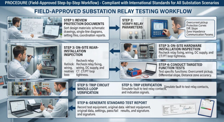
Protection relay testing and commissioning is the sequence of checks that proves a protection system trips when it should and stays stable when it should not. Device-level testing checks each relay against its setting file. System-level commissioning carries the trip…
Numerical Transformer Differential Protection: How Digital 87T Relays Work
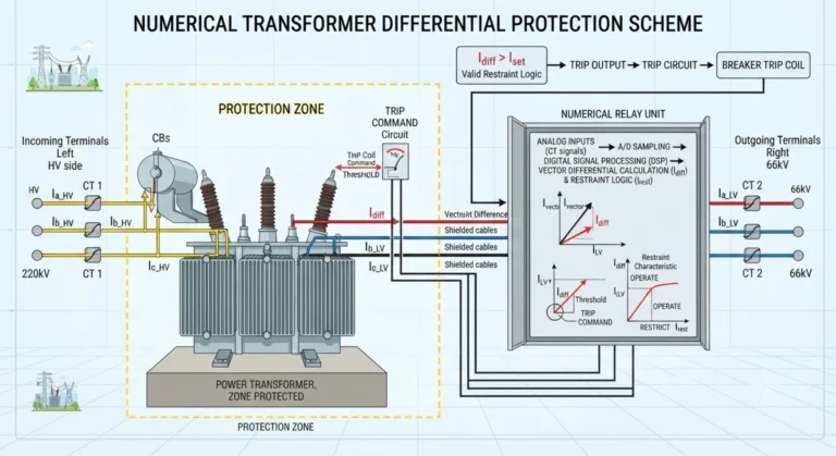
Numerical transformer differential protection is a microprocessor-based protection method used to detect faults within the defined protection zone of a power transformer. Unlike conventional electromechanical differential schemes, a numerical 87T relay can digitally process CT inputs, compensate for transformer ratio and vector group effects,…
Transformer Differential Protection Setting: Parameters, Calculation and Guidelines
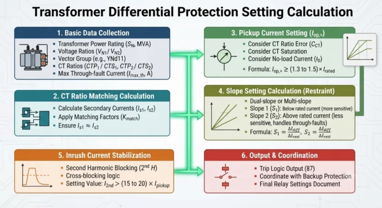
Transformer differential protection setting defines the operating parameters used to distinguish internal transformer faults from normal load, external faults, and transformer energization conditions. The main parameters include differential pickup, percentage bias or restraint slope, harmonic restraint, CT ratio, transformer vector…
What Is Backup Protection Relay? Principle and Application
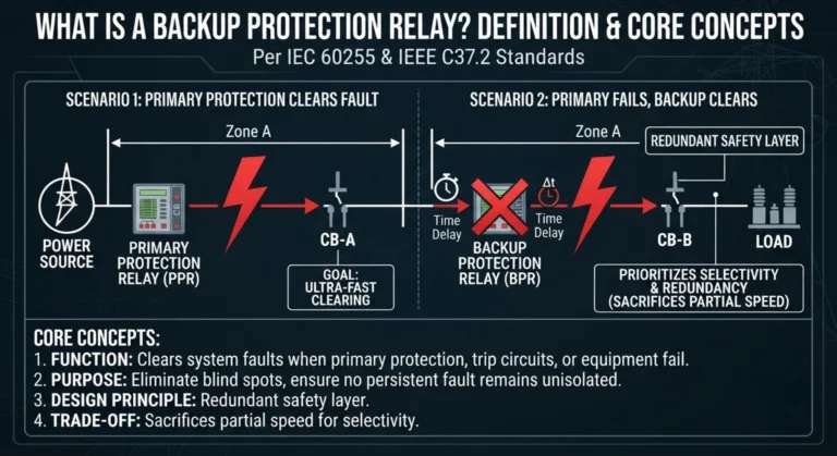
A backup protection relay is an independent second device that clears a fault after the primary protection has failed to trip or the breaker has refused to open. It buys certainty with time: it sits out a deliberate delay, then…
Differential Protection for Star-Star Transformer (Y-Y): Zero-Sequence and Tertiary Effects
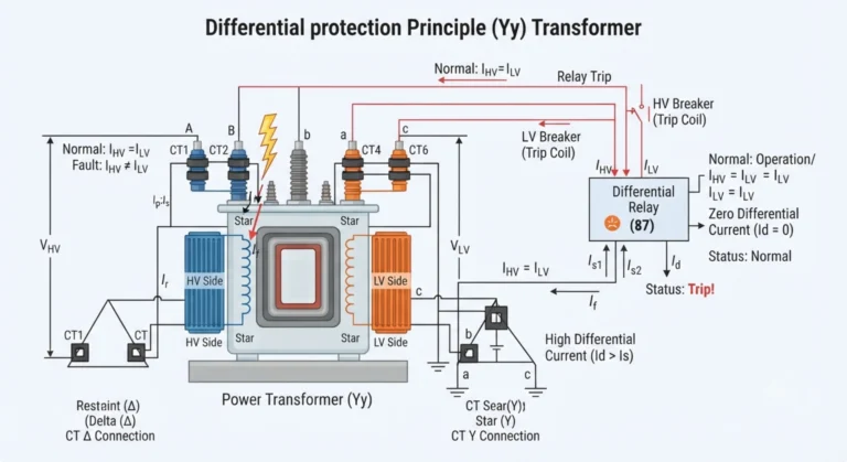
Introduction Differential protection for a star-star (Y-Y) transformer compares the compensated currents on the two sides of the transformer to detect faults within the protected zone. Written by Leon Zhang, Protection Application Engineer · Technical review by Li Ming, Electrical…
Complete Calculation & Interpretation of Three-Stage Overcurrent Protection for 10kV Feeder Cabinets
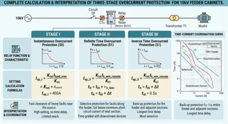
Three-Stage Overcurrent Protection Three-stage overcurrent protection splits one feeder fault across three ANSI elements: an instantaneous ANSI 50 stage with no intentional delay, a time-delayed ANSI 51 stage, and a definite-time ANSI 51 stage that backs up both. Each stage…
ANSI Protection Relay Codes: Device Number Chart
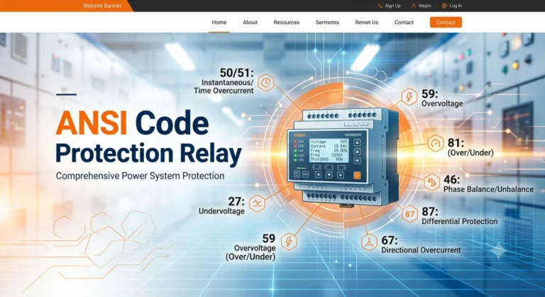
ANSI protection relay codes are the numeric function identifiers defined by ANSI/IEEE C37.2-2022: ANSI 50 for instantaneous overcurrent, ANSI 51 for time-delayed overcurrent, ANSI 87 for differential, ANSI 27 and ANSI 59 for voltage. One number names one protection function,…
High Quality
Stable performance, reliable design, ensuring safe operation for power system protection and grid stability.
Fast Delivery
Timely delivery to support your urgent orders and project schedules efficiently and professionally at any time.
Best Warranty
Professional Warranty: Reliable after-sales support for stable relay protection and long-term customer satisfaction.