
-
Leon Zhang Sales Manager
-
Email: sale@relayprotect.com
-
Phone/WhatsApp: +86 13655813266
Manual Transfer Switch for Generator Guide
A manual transfer switch for generator duty puts one interlocked handle between two sources: three positions, pole count, ratings and the changeover sequence.
What is a manual transfer switch for generator duty?
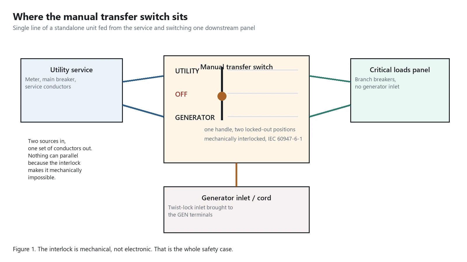
A manual transfer switch for generator duty is a listed assembly with its own enclosure and one handle that can only connect the load to a single source at a time. IEC 60947-6-1:2013 calls this class transfer switching equipment, whether a hand or a motor moves the handle. Contact ratings, interlock duty and break-before-make behaviour are proven by the manufacturer as one unit. Sizes cluster by market: residential units run from 30 A single-phase to 200 A, three-phase boards to 400 A, and above roughly 600 A the manual option gives way to motor-operated switchgear. The nameplate decides more than the catalogue, since AC-22A for mixed circuits is not interchangeable with the AC-3 figure a motor duty needs. The centre stop is most of what the money buys. Two sources connected at once would backfeed the utility network from a portable genset, so listed units prevent it mechanically rather than by operator discipline. Setting review and quotation within 12 hours, MOQ 1, 7-15 working days.
Manual transfer switch for generator duty is a listed switching assembly with its own enclosure, its own switching means and one handle that can only ever connect the load to a single source at a time. IEC 60947-6-1:2013 calls this class of equipment transfer switching equipment, whether a hand or a motor moves the handle.
At a glance
- The handle travels through an off position. That centre stop is what makes simultaneity mechanically impossible.
- IEC 60947-6-1:2013 covers transfer switching equipment of exactly this sort, hand operated or motor operated.
- Nothing inside the unit starts the generator. Every step of the sequence belongs to a person.
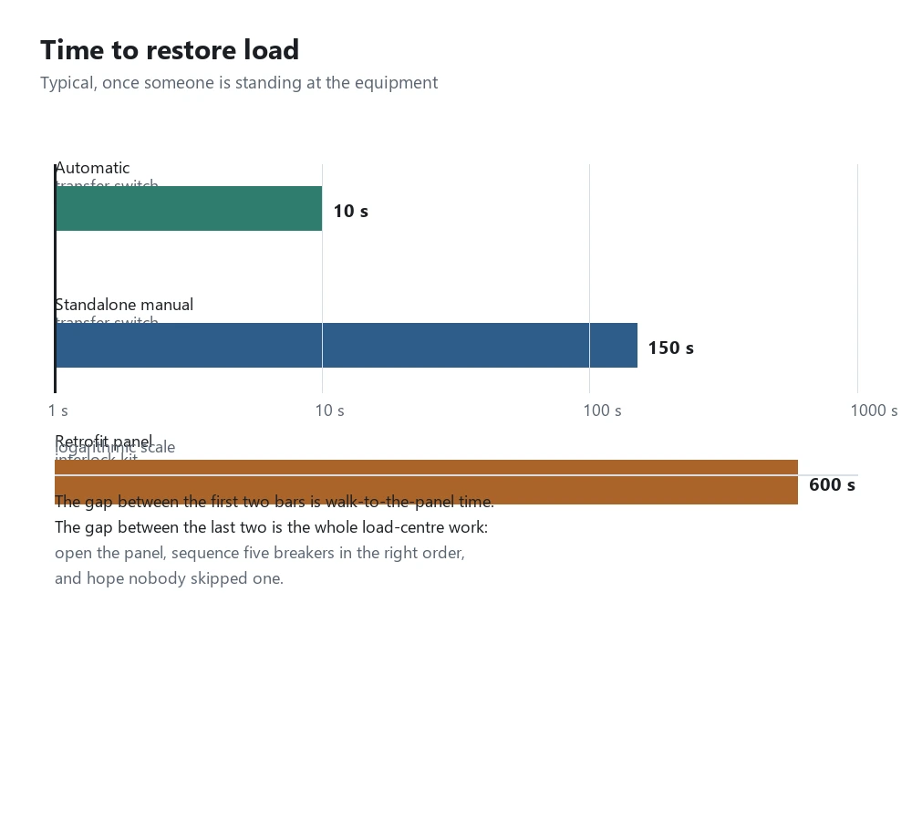
- Restoring load takes roughly two and a half minutes once someone is standing at the equipment.
- Starting current of the largest motor sets the frame size, not the sum of the running watts.
- A three-pole unit keeps a solid neutral. A four-pole unit switches it, which changes the grounding answer.
- NFPA 110:2025 puts weekly and monthly exercise duties on the whole standby system, not on one device inside it.
- An unattended site with a life safety load is not a manual application. It needs automatic changeover.
What a manual transfer switch for generator duty actually is
The device sits between the utility supply and a load panel, and it is a complete assembly rather than an accessory. Contact ratings, interlock duty and the break-before-make behaviour are all proven by the manufacturer as one unit, so nothing in the scheme depends on how the existing panel happens to be built.
Sizes cluster by market. Residential and light commercial units run from 30 A single-phase up to 200 A, three-phase versions are common to 400 A for small commercial boards, and above roughly 600 A the named manual option gives way to motor operated switchgear derived from IEC 60947-6-1 equipment.
Nameplate reading is where most specifications go wrong. The utilization category on the label tells you which load the continuous rating was proven against, and AC-22A for mixed circuits is not interchangeable with the AC-3 figure a motor-starting duty needs.
Three things the unit does not do.
Selecting a relay for a live project?
Send the system voltage, CT ratio and tripping scheme. Our engineers confirm the model and reply within 12 hours.
- It does not start the generator. No sensing circuit, no start contacts, no exercise clock.
- It does not decide when to transfer. Nobody measures voltage quality; a person decides.
- It does not protect anything downstream beyond whatever overcurrent device is built into it.
None of those three is a defect. A manual transfer switch for generator duty is bought precisely so that the transfer decision stays with a person who can see the site.
Three positions, one handle: why the off stop exists
A two-sources-connected condition energises the utility network from a portable genset, which kills utility line workers and destroys the generator in the same instant. Leaving the order to operator discipline is not acceptable to any listing body, so listed units prevent it mechanically.

Some designs need the handle pushed inward before it turns, which is a deliberate deterrent against the shoulder-bumping habit that develops on a dark staircase. Force one of those and you damage the interlock itself.
The centre stop is most of what the money buys. A manual transfer switch for generator duty turns a safety rule into geometry, and geometry survives an operator having a bad night.
How it differs from an interlock kit and from an automatic switch
Three ways of doing the same job sit in the same catalogue, and fryers routinely compare the wrong pair. The differences that matter are what actually switches, how many steps the operator takes, and how long it takes to get the lights back.
| Approach | What switches | Operator actions | Typical restore time |
|---|---|---|---|
| Standalone manual switch | One purpose-built unit in its own enclosure | Two lever moves through a locked off stop | About 150 s once on site |
| Retrofit panel interlock kit | Two existing breakers and a sliding plate | Five or more breaker operations in sequence | About 600 s, more in the dark |
| Automatic transfer switch | Motorised device plus a controller | None, the controller initiates and monitors | About 10 s from loss of supply |
Table 1. Three legal ways of not paralleling two sources, separated by what actually moves and by whom.
The retrofit route is a different product with its own article in this series, and it lives or dies by whether your panel accepts that manufacturer’s plate. Our piece on the transfer switch for generator covers all three families side by side, including automatic units built on contactors and motorised breakers.
The changeover sequence people get wrong
Most field failures are not equipment failures. They are order failures: the generator gets started into a house whose breaker people were left closed, or everything gets energised the instant supply returns.

The two places it falls apart are load management and re-energisation.
Starting the set with every downstream breaker closed puts the whole house load on the genset during its first three seconds, when speed recovery is worst and voltage is soft. A 5 kW unit asked to start a 1.5 kW well pump alongside 800 W of electronics will stall or trip on undervoltage, and the operator will read that as a generator problem. Shed everything, restore blocks largest first, and the same set behaves.
Re-energisation fails in the other direction. Inspectors who find a burned utility contact usually find it on a unit that was swung back to utility with every load still connected.
Ratings on a manual transfer switch for generator duty that decide the model
Five lines on the label carry the selection, and two of them are routinely quoted without their conditions. Read all five against the same duty.
| Line | What it really means | Typical value | What goes wrong when quoted loosely |
|---|---|---|---|
| Rated operational current, Ie | Continuous current at the stated utilisation category | 30 A to 400 A | A resistive rating applied to motor duty |
| Utilisation category | The load type the rating was proven against | AC-22A for mixed loads | Contact life collapses in months on tungsten loads |
| Rated short-time withstand, Icw | Fault current survived for 0.5 s or 1 s | 5 kA to 25 kA | Device rated below the fault available at its terminals |
| Number of poles | Whether the neutral is switched with the phases | 2, 3 or 4 pole | Two neutral-earth bonds fighting each other |
| Mechanical endurance | Operating cycles before scheduled replacement | 3,000 to 10,000 cycles | A weekly drill wears a low-cycle device in ten years |
Table 2. Five label lines, read as one set, and the failure each one predicts when read alone.
Pole count and the neutral question
The pole question is a grounding question wearing a switch suit. Decide it once, at specification time, because nothing about it can be adjusted in the field.
A three-pole unit leaves the neutral solid. The generator sees the same neutral-to-earth bond it would see if it were plugged into a house directly, so it is not a separately derived source and no additional bonding is required at the set. This is the common configuration for portable units feeding a panel through an inlet.
A four-pole unit switches the neutral too, creating a separately derived system on the generator side. That means a second neutral-to-earth bond at the set, an electrode at the generator, and a grounding scheme that has to be drawn rather than assumed. Choose it when the load needs genuine isolation from the utility neutral, typically where sensitive electronics share the board or where the supply arrangement already carries multiple bonded sources.
Sizing: starting current sets the frame
Running watts get quoted. Starting current decides whether the plant survives.
A 1.1 kW submersible well pump draws maybe 1.6 kW running and pulls five to six times that for the 1.5 s it takes to reach speed. A 3.5 tonne air conditioner at 4 kW running can ask for 18 kW at locked rotor. Two of those starting together on a 10 kW set is a voltage collapse, not a nuisance trip, and no amount of switch rating changes the outcome.
Work the numbers in three steps. Add the running load of what must stay live, add the largest single motor starting figure on top, then divide by both the power factor and the derating for altitude and temperature if either applies. The result lands in a frame size, and the frame lands in a cost.
Installation: feeding from the meter or from the panel
Wiring a manual transfer switch for generator service for the first time is mostly a routing decision. Feed-through units are placed between the meter and the existing load centre, so everything downstream transfers as a block. Branch units take a handful of circuits out of the main panel and into a dedicated emergency sub-panel, which keeps large loads out of the generator budget and usually costs less conductor.
Separation rules still apply. Line and load conductors cannot share a raceway with each other in most installations, the generator inlet conductor belongs in its own conduit, and an inlet mounted outdoors needs a listed enclosure and a weatherproof cover that closes over an inserted plug.
Testing, exercise and the annual drill
NFPA 110:2025 places monthly testing and periodic load testing duties on the emergency power supply system as a whole. A unit that sits untouched eleven months of the year develops exactly the failure the standard is written to catch.
Run the full sequence monthly, not just the generator. Transfer under load, note how long it took, and note whether any contact felt gritty. Check the inlet for heating and corrosion, confirm the utility and generator conductors are torqued, and operate the upstream breaker twice so its mechanism does not seize. Our notes on general panel arrangements for emergency generator panels cover the upstream protection that usually shares the enclosure.
Where the utility back-feed prohibition comes from
The rule is not a paperwork preference. A genset energising a dead utility conductor presents thousands of volts at equipment that the utility believes is isolated, and line crews work on that assumption.
NFPA 70:2023 treats approved transfer equipment as the required means of avoiding that condition, and code language consistently describes the interlock as mandatory rather than recommended. Any arrangement relying on an operator remembering sequence, including the improvisation of a double-male cord, fails the requirement before it fails physically.
When a manual transfer switch for generator duty is the wrong answer
Four applications arrive every year that this product cannot serve, and each one has a different correct answer.
- Unattended sites with life safety loads. Nobody is there to move the handle, and NFPA 110 class expectations for a Type 10 system cannot be met by anyone walking to a panel. Specify automatic changeover
- Loads that tolerate no break at all. Even a perfect operator takes minutes. Servers, imaging equipment and process controls need a transfer small enough that the load never notices, which means static bypass or a UPS in front of anything mechanical.
- Whole service transfer above roughly 400 A. The manual option disappears from most catalogues at that point, and the mechanical effort and arc energy move into motor operated switchgear territory.
- Anyone intending to run the generator in parallel with the utility. This product exists to make paralleling physically impossible. Forced operation breaks the interlock rather than achieving the goal.
Conclusion
Manual transfer switch for generator duty trades convenience for a certainty that nothing can parallel the two sources, and does it at a fraction of the cost of anything automatic. Get the frame size from motor starting rather than running watts, pick the pole count from the grounding scheme rather than habit, and give the operator a written sequence on the door. Those three decisions decide whether the installation works on its worst night.
Then check what rotates the handle. Every automatic option puts contactors or motorised breakers in the same slot and hands the timing to a controller, and our ATS controller page lists what that controller has to sense before it moves anything.
Frequently asked questions
Can I install one myself?
It depends on the jurisdiction and on whether the work involves service entrance conductors, but in most places the connection falls under electrical permit and inspection. Even where self-installation is permitted, the work carries serious consequences if done incorrectly, because a wiring error can put generator voltage onto utility conductors.
Do I need a two-pole, three-pole or four-pole unit?
Match it to the grounding arrangement rather than to habit. A three-pole unit leaves the neutral solid and suits a portable set that feeds the structure as though it were plugged straight in. A four-pole unit switches the neutral as well, which creates a separately derived source and calls for its own neutral-to-earth bond and electrode at the set. Four-pole is the answer where the load genuinely needs isolation from the utility neutral, for example when sensitive electronics share the board.
What size generator does my installation need?
Size for starting current, not the sum of running loads. Motor inrush, not running watts, sets the frame. Add the continuous load you must keep energised, add the locked-rotor current of the largest motor on top, then derate for altitude and ambient temperature. A 10 kW set with soft starting on the compressor often beats a 14 kW set asked to hard-start it.
Can the unit be mounted outdoors?
Only if the enclosure carries a rating for it, typically NEMA 3R or better with the same immunity to rain and ice. Indoor enclosures moved outside corrode at the interlock pivots, and a seized pivot is the most common reason a manual unit refuses to move during an outage.
Does the switch protect against overload?
Sometimes. Units built with fused pullouts or moulded-case breakers inside do provide overcurrent protection. Others are switching devices only, and the overcurrent device has to sit upstream. Check the model sheet and do not assume. Where protection is absent it belongs in the upstream panel, and the impedance of that panel has to be checked against the prospective fault, as set out in our guide on choosing breakers.
How often should it be exercised?
Monthly, and with load on it rather than empty. NFPA 110:2025 expects the emergency power supply system to be exercised regularly under load, which means transferring rather than simply starting the set. If it is only ever moved during real outages, the interlock will not move twelve months from now.
Exercise the protection as well. Operate the upstream breaker twice a year so its mechanism and trip coil get a current pulse, and log the winding resistance or contact resistance trend while the circuit is open.
Can it damage my generator?
Not the transfer switch itself, because it neither loads nor unloads the set. The mechanisms that hurt generators are starting into a full house load, running lightly loaded for long periods, and transferring back under load. Sequence discipline prevents all three.
Related reading
- Transfer switch for generator, all three families compared side by side.
- Emergency generator panel, the upstream protection that shares the enclosure.
- Circuit breakers, matching the frame to the prospective fault.
- Substation, where this equipment sits in the wider arrangement.
Sources and standards
| Source | What it covers | Type | Edition |
|---|---|---|---|
| IEC 60947-6-1:2013 | Transfer switching equipment: automatic and manual, ratings and tests | Standard | 2013 |
| IEC 60947-3:2015 | Switches, disconnectors and fuse-combination units | Standard | 2015 |
| IEC 60947-2:2016 | Low-voltage circuit-breakers used as the switching means | Standard | 2016 |
| IEC 60947-4-1:2023 | Contactors used inside automatic transfer assemblies | Standard | 2023 |
| NFPA 110:2025 | Emergency and standby power systems: testing and exercise duties | Standard | 2025 |
| NFPA 70:2023 | Electrical installation requirements for approved transfer equipment | Standard | 2023 |
| ANSI/IEEE C37.2-2022 | Device function numbers including 83 selective transfer | Standard | 2022 |
| IEC 60364-5-51:2023 | Selection and erection of electrical equipment | Standard | 2023 |
Table 3. Standards referenced above, with the edition each figure in this guide was taken from.
Sequence timings and load-figure examples come from our own commissioning records on residential and light commercial standby installations between 2021 and 2026. They describe what we measured on those sites and nothing beyond them.
For a model recommendation, send the system voltage and the load details to our engineering team.
About Author

Hello, I'm Leon Zhang. I have 15 years of experience in the power relay protection industry with extensive pre-sales and after-sales project experience. Our company specializes in various complete sets of relay protection and automation equipment. I can assist customers in solving all practical on-site project challenges and provide optimal integrated solutions.
Tell Us Your Requirement



High Quality
Stable performance, reliable design, ensuring safe operation for power system protection and grid stability.
Fast Delivery
Timely delivery to support your urgent orders and project schedules efficiently and professionally at any time.
Best Warranty
Professional Warranty: Reliable after-sales support for stable relay protection and long-term customer satisfaction.