
-
Leon Zhang sales consultant
-
Email: zxl635973785@gmail.com
-
Phone/WhatsApp: +86 13655813266
PLC Controller (Programmable Logic Controller): A Guide
A programmable logic controller reads inputs, runs a stored program and writes outputs every 5 to 20 ms. This guide covers the hardware, scan timing and I/O.
Programmable logic controller is the industrial computer that runs a machine, a pump set or a plant section. It copies every input into memory, executes a stored program against that copy, writes every output back, and repeats. One pass takes 5 to 20 ms on a typical unit.
At a glance
- A programmable logic controller is a cyclic digital computer: read inputs, run the program, write outputs, repeat.
- IEC 61131-2:2017 covers the hardware requirements and tests. IEC 61131-3:2013 defines the five programming languages.
- Quoted scan time is the worst case at full point count, not the average on an empty rack.
- A physical input that changes mid-scan waits for the next cycle. No setting removes that delay.
- 24 V DC optocoupler inputs carry a 3 to 7 ms filter that sits outside the scan, before it starts.
- A relay output lasts about 100,000 operations. A transistor output lasts millions and switches in under a millisecond.
- Above roughly 20 analog loops under PID control, a DCS starts to earn its price over a PLC.
- Cabinet air above 55 °C takes you outside the standard rating, and conformal coating is a separate order line.
What Is a Programmable Logic Controller, Exactly?
The short answer: a ruggedised digital computer with no screen, no keyboard and no operating system you can log into, built to sit in a cabinet at 50 °C and switch 24 V all day. It holds a program in non-volatile memory and executes that program continuously. Everything else about the product follows from the second half of that sentence.
The cyclic part deserves emphasis. A desktop program waits for events. A programmable logic controller does not wait. It walks the whole program from the first rung to the last, then starts again, whether or not anything changed.
That predictability is what plant engineers actually buy. Two identical machines running identical programs execute the same sequence in the same order at the same interval, so a fault can be reproduced by reproducing the input pattern. No amount of debugging skill substitutes for that property when the plant is down and the clock is running.
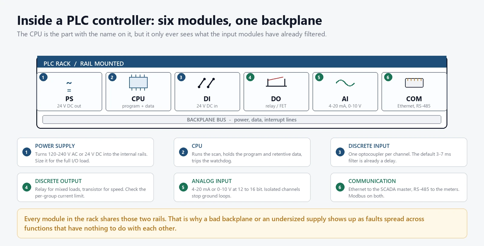
Inside a Programmable Logic System: Six Modules on One Backplane
A rack-based programmable logic controller is a set of modules plugged into a common backplane, which carries power, the data bus and the interrupt lines. Six module types cover almost every application, and knowing what each one does is the fastest way to read a bill of materials.
The power supply converts 120-240 V AC or 24 V DC into the internal rails. Size it against the total I/O load rather than the CPU, and allow for transformer inrush on a cold morning as well as steady draw. A supply running above 80 percent of rating in a 55 °C cabinet is a supply that fails in year three.
The CPU holds the program, the retentive data and the scan clock, and it runs the watchdog. A watchdog trip means the program took longer than the configured maximum, so the controller stops rather than driving outputs from stale data. That is the correct behaviour and it still stops the plant.
Discrete inputs are optocouplers. Each channel sees 24 V DC and reports one bit. The default filter is 3 to 7 ms, long enough to reject contact bounce and short enough for a pushbutton. It is also long enough to lose a 2 ms pulse entirely, so a latching input that has to hold a short pulse needs the filter set explicitly.
Discrete outputs come in two flavours and the difference matters. A relay output is a dry contact, handles mixed AC and DC loads, and dies after roughly 100,000 operations at rated current. A transistor output switches in under a millisecond, lasts effectively forever, and cannot drive an AC load at all. Read the nameplate on the contactor coil before you decide which one to specify.
Analog inputs take 4-20 mA or 0-10 V at 12 to 16 bit. Isolated channels cost more per point and are the ones that stop a ground loop.
The communication module gets specified last and causes the most rework. Ethernet to the SCADA master, RS-485 to the meters, and sometimes a second port for a programming laptop on its own subnet. Compact controllers fold all six functions into one housing, at the cost of a fixed point count and a fixed mix.
The Scan Cycle, and the Timing Problems It Explains
The cycle has four steps and the order never changes. Input scan copies every physical input into an image table. Program execution runs the whole program against that table. Output update writes the table to the output cards. Housekeeping handles diagnostics and communication with whatever time is left.
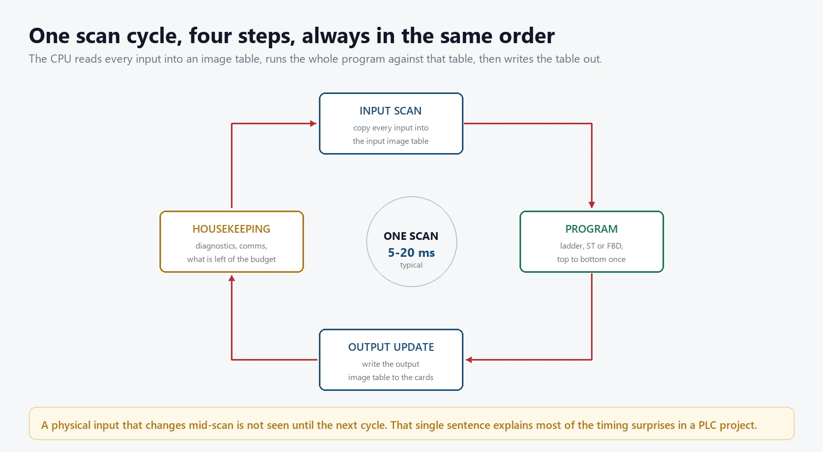
Most timing surprises in a PLC project come from one sentence: a physical input that changes in the middle of a scan is not seen until the next one. A program that reads the same input in rung 3 and rung 300 reads the same value in both places, even if the field device changed in between.
Consistent inputs for one whole scan. That consistency is also why a fast interlock written in ladder logic can miss an event that a hardware relay would catch.
Three techniques recover the missing milliseconds, and each costs something. Interrupt inputs let a channel break into the cycle and run a short routine immediately, at the price of a program that is no longer strictly sequential. Module-level interrupts latch the event in hardware and let the program collect it later, which is cleaner for a pulse counter. The third option is to stop using the PLC for that function: a safety interlock that must open in 10 ms belongs in a safety relay or a hardwired circuit, and IEC 61508-1:2010 treats it as a separate layer for good reason.
If the process time constant is under a second, look at the scan time before you look at the PID tuning.
Programmable Logic Controller vs DCS vs Relay Logic
Four controller families compete for the same panel space and they are not interchangeable. The choice usually gets made on price and then justified on architecture, which is backwards.
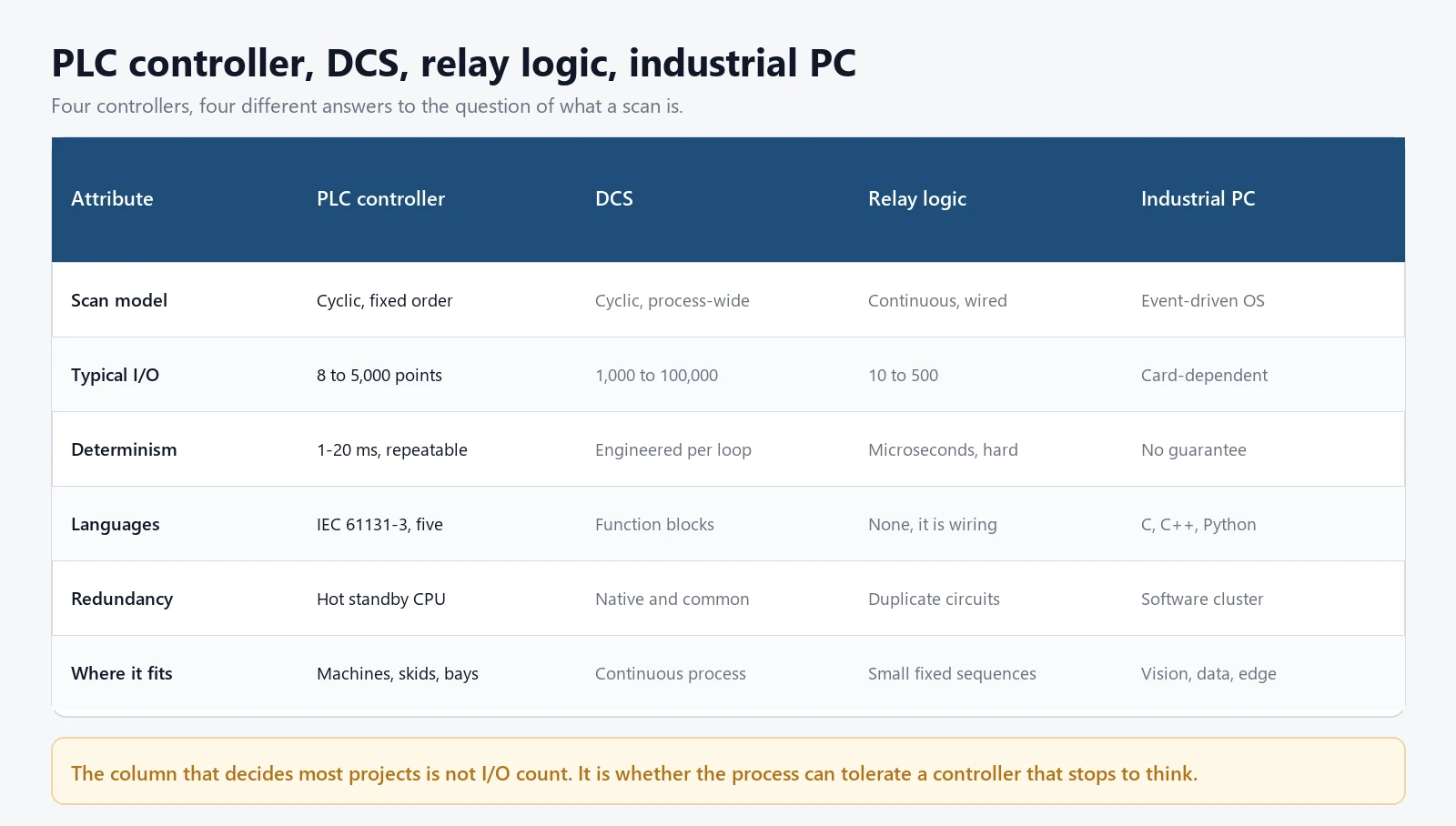
A DCS is built around the process loop rather than the machine sequence. Its operator stations, history and alarm management are part of the product, not add-ons. On a continuous process with hundreds of loops and a control room, that integration repays the extra cost. On a pump station with 40 digital points and two analog inputs, it is money with no return.
An industrial PC wins where the workload is not control at all: vision, data logging, edge analytics, a custom operator interface. Running the machine sequence on the same box is possible and usually a mistake, because the two workloads have different failure modes and different update cycles.
Mixed architectures are common: a controller runs the sequence, a DCS or SCADA master supervises, an IPC handles the data. The interfaces between them are where projects go wrong, so define them before choosing hardware.
What Is Programmable Logic Control? Four Products Behind One Name
The term has drifted. When someone says PLC today they may mean any of four things, and the specification changes with the answer.
A classic PLC is the rack or compact unit described above: cyclic, ladder-first, 24 V I/O, programmed with the vendor’s tool. This is still most of what ships into water treatment, pumping and building services.
A PAC, or programmable automation controller, is the same idea with a real-time multitasking kernel, more memory, and support for motion, vision and higher-level languages. The line between a large PLC and a PAC is a marketing line, not a technical one. If the application needs multitasking and floating-point maths at speed, the label does not matter.
A safety PLC is a separate product with redundant processing, certified diagnostics and a functional safety rating. It is not a standard PLC with a safety program loaded. IEC 61508-1:2010 sets the framework, and the machine sector standards set the level each function needs.
A soft PLC is a runtime on an industrial PC. It brings the IEC 61131-3 languages to general hardware, which is attractive for retrofits and for anyone who wants portable code. It also inherits every weakness of the operating system underneath, which is why it stays out of the trip path. Name the category explicitly in a specification, or a supplier can quote a soft PLC against a hardware requirement and still be compliant.
I/O Points and What Each Type Costs You
The point count on a quotation is not the point count on the drawing. Cards come in fixed sizes, spare capacity is not optional, and the type of point changes the price per channel by a factor of ten.
| Module type | Typical signal | Resolution | Points per card | What drives the cost |
|---|---|---|---|---|
| Discrete input | 24 V DC, sinking or sourcing | 1 bit | 16 or 32 | Channel isolation and the settable filter range |
| Discrete output, relay | Dry contact, 2 A | 1 bit | 8 or 16 | Contact rating and how many commons per card |
| Discrete output, transistor | 24 V DC, 0.5 A | 1 bit | 16 or 32 | Switching speed and short-circuit protection |
| Analog input, current | 4-20 mA, 250 ohm burden | 12 to 16 bit | 4 to 8 | Channel-to-channel isolation |
| Analog output | 4-20 mA | 12 bit | 2 to 8 | Drive capability and slew rate |
| RTD input | PT100, 3-wire | 0.1 °C | 4 to 8 | Linearisation and lead resistance compensation |
| Thermocouple input | Type J or K | 0.1 °C | 4 to 8 | Cold junction compensation accuracy |
Table 1. I/O module types and the specification item that moves the price.
Reserve 15 to 20 percent spare I/O on every card type, and reserve it as terminals rather than as a note on the drawing. A spare that needs a new card and a new cable before it can be used is not a spare.
Group outputs by load type. Relays for solenoids and contactor coils, transistors for pilot lights and fast pulses. Put a varistor or an RC suppressor across every inductive load, because a coil that switches off without one will eventually weld a contact and take the group common with it.
Programming: The Five Languages of IEC 61131-3
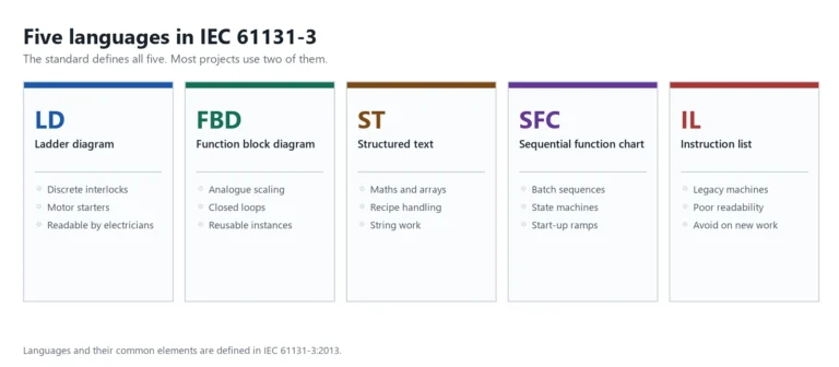
IEC 61131-3:2013 defines five languages. Every mainstream PLC controller supports at least three of them, and most support all five. The choice is less about preference than about who has to read the code at three in the morning.
Ladder diagram is the default for discrete logic because it looks like a relay schematic, so an electrician can read it without training. That readability is worth more than the elegance of any alternative when the person debugging it did not write it. Function block diagram suits signal processing and analog chains, because blocks with defined inputs and outputs map onto how instrumentation engineers already think about a loop.
Structured text is Pascal-like and handles maths, loops and string work that ladder makes painful. It is also the language most likely to be unreadable six months later, because it lets the author be clever. Sequential function chart models a machine as states and transitions, which beats any amount of ladder for a batch sequence or a startup procedure, since the drawing shows exactly where the sequence is stuck. Instruction list is the assembly-level language of the standard; edition 3 deprecated it, so new projects should not start there.
The practical rule: ladder for interlocks and discrete sequences, function blocks for analog, structured text for calculations, SFC for batch. Mixed code is normal and healthy.
How to Read a Programmable Logic Controller Scan Time Specification
Datasheets quote scan time three ways and only one of them is useful. The first is an instruction execution time in microseconds, which describes the CPU. The second is a typical scan on a small benchmark, which is the optimistic case. The third is the maximum at full point count, which is the number that decides whether the machine works.
Ask for the third one in writing, at your point count, with your communication load.
| Stage | Typical time | What sets it | How to shorten it |
|---|---|---|---|
| Input filter | 3 to 7 ms | The module’s default filter setting | Set it to 0.1 ms on the channels that need it |
| Backplane transfer | 0.05 to 0.2 ms per module | Rack size and bus speed | Fewer, denser modules |
| Program execution | 1 to 50 ms | Instruction count and CPU class | Move time-critical code to an interrupt task |
| Output update | 0.1 to 0.5 ms | Output point count | Very little, this is already small |
| Communication slice | 0.5 to 5 ms | Protocol and poll rate | Put comms in a separate task, or a separate module |
Table 2. Where the milliseconds in a scan actually sit, and which of them you can move.
Two rows in that table are outside the program’s control. The input filter runs in hardware before the scan starts, and the backplane transfer is fixed by the rack you bought. Together they can add 10 ms before a single rung executes.
Which is why a controller with a 1 ms scan can still miss a 5 ms event. Communication sits in the same trap: a Modbus RTU poll at 9600 baud across 20 slaves can take 400 ms for a full round, so if the program waits for that data before deciding, the effective update rate is the poll rate and not the scan rate. Move the wait out of the sequence, or move the poll to a faster link.
Communication: What Actually Reaches the SCADA Master
Every project has at least two networks and usually three: the I/O bus inside the rack, the control network between controllers, and the supervision link to SCADA. Conflating them is a common and expensive mistake.
| Protocol | Physical layer | Typical cycle | Determinism | Where it earns its place |
|---|---|---|---|---|
| Modbus RTU | RS-485, two wire | 100 to 500 ms | Polled, no time slot | Meters, VFDs, existing panels |
| Modbus TCP | Ethernet | 10 to 100 ms | Polled over TCP | SCADA link, the usual default |
| Profinet RT | Ethernet | 1 to 10 ms | Cyclic, prioritised | Machine cells with drives |
| EtherNet/IP | Ethernet | 1 to 10 ms | Cyclic over CIP | North American machine builders |
| IEC 61850 GOOSE | Ethernet | Under 3 ms | Publisher and subscriber | Substation interlocking |
| OPC UA | Ethernet | 10 to 100 ms | Client-server or pub-sub | Historian and MES integration |
Table 3. Six protocols a PLC controller is likely to speak, and what each one is good at.
Modbus TCP remains the default because it is simple, free to implement and understood by every SCADA package. It has no time stamping, no quality flag and no security. On an isolated control network that is acceptable; on a network with a vendor remote-access link it is not.
IEC 61850 appears when the controller sits inside a substation and has to exchange interlocking signals with protection relays. GOOSE messages repeat until they are superseded, so a lost packet costs one cycle rather than the whole message. For that job there is no practical substitute.
OPC UA is the link that survives a change of vendor. If the data has to reach a historian, an MES or a cloud platform, put OPC UA at that boundary and keep the control network on whatever the machines already speak.
Our own LCU cabinets use Modbus TCP to the station SCADA and RS-485 to the field meters, on separate ports. When a meter loop fails, the SCADA link keeps running. That separation costs one Ethernet module and has paid for itself more than once. The protocol trade-offs are set out in this comparison of Modbus, IEC 60870-5 and IEC 61850.
Where PLC Controls Sit in a Station or Plant
The same controller appears under different names depending on the plant. In a pumping station it is the sequence layer inside an LCU cabinet. In a substation it is the bay controller. On a machine it is the cell controller.
In a pump station, programmable logic controllers handle start and stop sequencing, level-based staging, valve interlocks and run-hour rotation between pumps. The protection relays sit beside the controller and trip the breaker directly, and differential protection stays in the relay where it belongs. The controller never decides whether to trip; it decides what starts, in what order, and under what conditions. Keeping that boundary clean is the most important design rule in the panel.
That boundary blurs during commissioning. A programmer under pressure will add a software interlock that duplicates a protection function, and the duplicate is slower and less tested. If the function protects equipment, it belongs in a relay. A worked example of the arrangement is in this guide to pump station automation and SCADA control.
In a substation the requirements tighten. The controller has to survive EMI from switching, report time-stamped events to the millisecond, and speak a protocol the protection relays already use. IEC 61000-4 testing and IEC 61850 conformance are not optional there.
The panel around the controller is where a specification usually stops short. A programmable logic controller panel carries a 24 V supply sized for the whole I/O load, an interface relay for every protection trip, a marshalled terminal row for the field cables and a service outlet for the programming laptop. Programmable logic controller software ships with the hardware and usually locks to it, so the licence, the programming cable and the firmware revision belong in the panel schedule next to the point count.
Six Questions Before You Compare Prices
Most controller selections start with a point count and a budget. Both are the wrong first question, and both are easy to answer later.
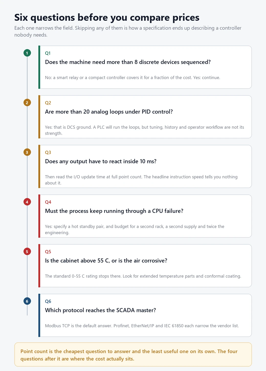
Question one is the device count. Below about eight discrete devices, a smart relay does the job for a fraction of the cost. Above that, wiring and documentation grow faster than the function, and the controller pays for itself.
Question two is the analog loop count. Twenty PID loops is roughly where a DCS becomes the better answer, not because a PLC cannot run them but because tuning, history, alarm management and operator workflow are not what it was designed to provide.
Question three is response time, and Table 2 already answers it: the I/O update time at full point count, not the instruction speed.
Question four is redundancy. A hot standby CPU pair doubles the rack, the power supply, the engineering hours and the spare parts stock. Right for a process that cannot stop, wrong for a machine that restarts in 30 seconds. Question five is the environment: the standard rating stops at 55 °C, and extended temperature parts plus conformal coating are separate order lines.
Question six is the protocol. Modbus TCP keeps the field wide. Profinet or EtherNet/IP narrows it to a handful of families. IEC 61850 means a substation controller, and the price changes with it.
Answer those six and the shortlist usually contains three products.
When a Programmable Logic Controller Is the Wrong Choice
Four situations where the specification should point somewhere else, and the cost of ignoring them shows up after the first year.
- Fewer than eight devices, fixed forever. A smart relay does the same job for a fifth of the price and a technician can change it without software.
- Any function that must act inside 10 ms. Standard scan architecture cannot guarantee it. That function belongs in a safety relay or a hardwired circuit.
- Hundreds of analog loops with a control room. A DCS carries the tuning, history and alarm tools as part of the product. Rebuilding them on a PLC is a project in itself.
- A 55 °C cabinet with no cooling budget. Standard parts derate above that, and no firmware setting recovers the margin.
None of those four is unusual.
Where Commissioning Goes Wrong
Five faults account for most of the commissioning time we see, and four are documentation problems.
None of them is exotic.
Point-to-point checks that test the card, not the field device. Forcing an input in software proves the program sees the bit. It does not prove the wire reaches the terminal, and the wire is what fails.
Analog scaling left at default. A 4-20 mA input scaled 0-100 percent in the program, shown as 0-100 on the HMI, and calibrated 0-10 m in the field is three ranges held together by convention. Write the range on the loop drawing and check it at 4, 12 and 20 mA.
No test of the failure path. Pull a card, drop the communication link, power down one supply. The program should reach a defined state, not the state the last scan happened to leave in the output table. Retentive memory settings decide this, and they are usually left at default.
Scan time measured on an empty program. The number goes into the record, the plant gets loaded, and the real scan is four times larger. Measure it at the end of commissioning with the full program and the full communication load.
No backup of the final program. Not last week’s version, and not the copy on the engineer’s laptop. The commissioned program, with comments, on two media, with the checksum written into the panel schedule.
Conclusion
A programmable logic controller is a cyclic computer with plant-rated I/O, and almost every property that matters follows from the word cyclic. The scan order makes behaviour reproducible. The image table makes the program insensitive to mid-scan changes. The fixed cycle also sets the resolution of everything the controller can react to, which is why the scan time belongs in the specification and not in the appendix.
Choose the category before the model. Machine sequence, process loop, hardwired logic and data workload each have a natural home, and picking the wrong one produces a system that works and is expensive to keep working. Then answer the six questions, reserve real spare I/O, and write down the scan time you actually measured.
Frequently asked questions
Is a PLC the same as a programmable controller?
In practice, yes. PLC stands for programmable logic controller, and the longer phrase adds no new requirement. Both refer to a cyclic industrial computer with modular I/O and a standardised programming environment.
How fast does a PLC scan?
A compact unit on a small program runs in 1 to 5 ms. A rack controller with a few hundred I/O points typically lands between 10 and 20 ms. Large programs with heavy communication reach 50 to 100 ms. Ask for the figure at full point count, because the datasheet number is usually measured on a benchmark far smaller than your program.
Can a PLC run without an HMI?
A controller can, and many do. The controller needs no display to execute its program. What it needs is a way to report state and accept setpoints, and without an HMI that job falls to a SCADA link or to physical selector switches. Running blind is acceptable for a fixed sequence. It is not acceptable where an operator has to change a setpoint.
Should I specify a PLC or a PAC?
Specify the function, not the label. If the application needs multitasking, motion control, floating-point maths at speed or high-level language support, you are in PAC territory whatever the vendor calls the product. If it needs discrete sequencing with interlocks and a handful of analog loops, a standard PLC controller is cheaper and easier to maintain.
Do I need a safety-rated controller?
Only for functions that the risk assessment assigns a safety integrity level. Those go in a certified safety controller or a hardwired safety circuit, not in the standard program. A standard PLC can report safety status to SCADA, but it must not be the only thing between a person and a moving machine.
How many spare I/O points should I reserve?
Fifteen to twenty percent of each point type, wired to terminals. Reserve it physically. A spare channel that needs a new card and a new cable before it can be used is not a spare, and the shutdown to install it costs more than the card.
What temperature range does a PLC tolerate?
The standard rating under IEC 61131-2:2017 is 0 to 55 °C ambient at the module, not at the cabinet door. Extended versions reach -20 to 60 °C. Above 55 °C the derating applies to output current first, which is the specification people miss, and a cabinet in direct sun exceeds it every summer.
Is a PLC the same as an LCU?
No. An LCU, or local control unit, is a cabinet built around a PLC, with the power supply, protection interface, indication and communication equipment the station needs. The controller is one component inside it. An LCU can also be built on a dedicated controller rather than a general-purpose PLC, which is common in hydropower where unit sequencing is fixed.
Related reading
- Pump station automation and SCADA control, the same controller doing sequence work in a water application.
- PLC control panel for hydropower and pumping stations, the LCU cabinet built around this controller.
- SCADA: a practical guide, the supervision layer above the controller.
- Modbus, IEC 60870-5 and IEC 61850 compared, for the protocol decision in Table 3.
- Secondary equipment in distribution rooms, where the controller sits among the relays and meters.
Sources and standards
| Source | What it covers | Type | Edition |
|---|---|---|---|
| IEC 61131-1:2003 | Programmable controllers, general information and definitions | Standard | 2003 |
| IEC 61131-2:2017 | Programmable controllers, equipment requirements and tests | Standard | 2017 |
| IEC 61131-3:2013 | Programming languages: ladder, function block, structured text, instruction list, SFC | Standard | 2013 |
| IEC 61010-2-201:2017 | Safety requirements for control equipment | Standard | 2017 |
| IEC 61508-1:2010 | Functional safety of electrical and electronic safety-related systems | Standard | 2010 |
| IEC 62443-4-2:2019 | Security requirements for industrial automation components | Standard | 2019 |
| IEC 61439-1:2020 | Low-voltage switchgear and controlgear assemblies | Standard | 2020 |
| ANSI/IEEE C37.2-2022 | Device function numbers used on the panel drawings | Standard | 2022 |
| UL 508A | Industrial control panels, North American market | Standard | Current |
Table 4. Standards referenced above, with the edition each figure in this guide was taken from.
Field figures in this guide come from our own panel builds and commissioning records between 2023 and 2026, on pump station LCU cabinets and 415 V distribution boards. They describe what we measured on those installations.
About Author

Hello, I'm Leno Zhang. I have 15 years of experience in the power relay protection industry with extensive pre-sales and after-sales project experience. Our company specializes in various complete sets of relay protection and automation equipment. I can assist customers in solving all practical on-site project challenges and provide optimal integrated solutions.
Tell Us Your Requirement
High Quality
Stable performance, reliable design, ensuring safe operation for power system protection and grid stability.
Fast Delivery
Timely delivery to support your urgent orders and project schedules efficiently and professionally at any time.
Best Warranty
Professional Warranty: Reliable after-sales support for stable relay protection and long-term customer satisfaction.