
-
Leon Zhang sales consultant
-
Email: zxl635973785@gmail.com
-
Phone/WhatsApp: +86 13655813266
Circuit Breakers: A Practical Guide
Where circuit breakers differ from isolators and fuses, the Icu, Ics and Icw ratings that decide survival, trip curves, and five field failure modes.
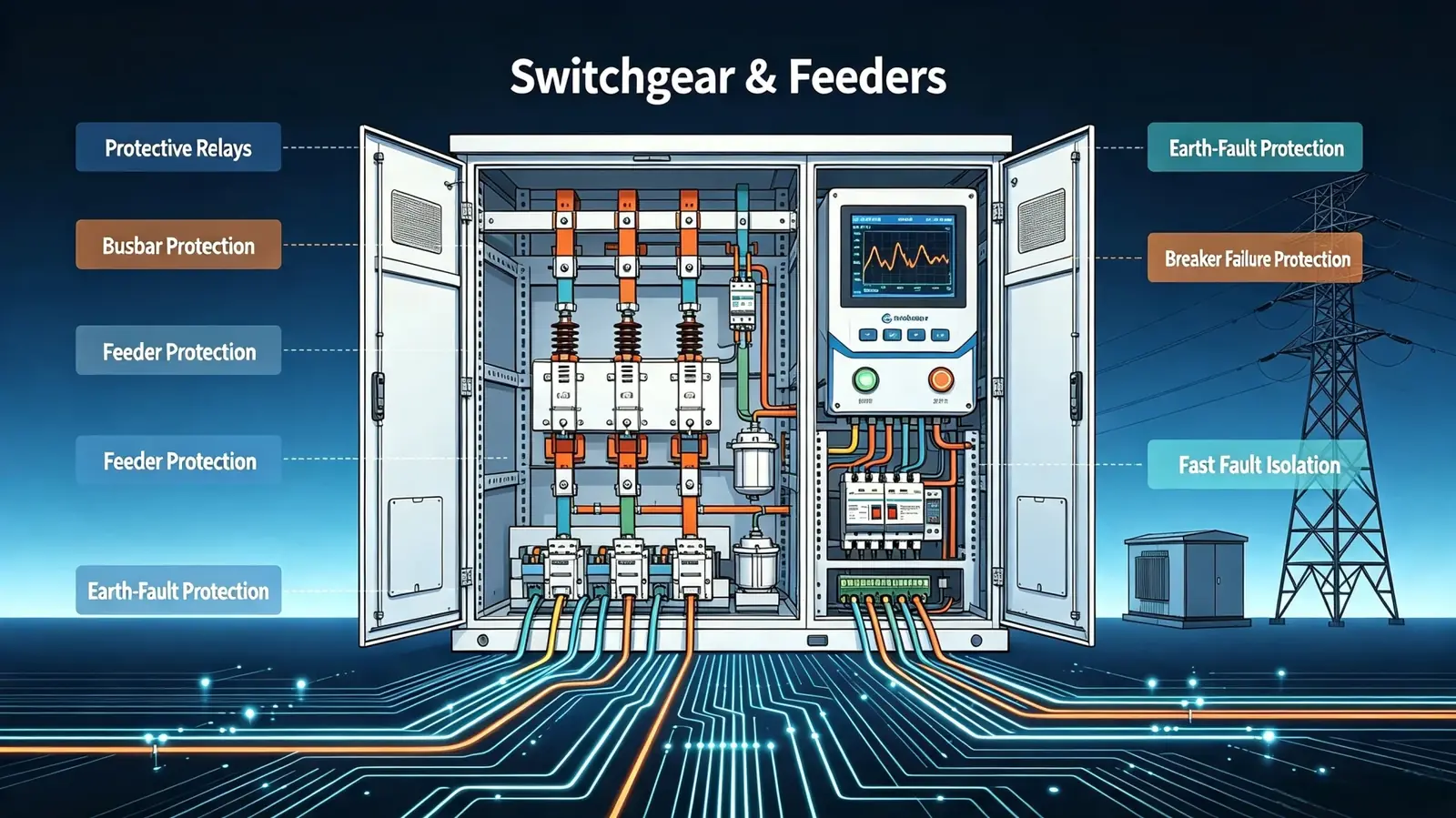
Circuit breakers, the electrical breakers that guard a panel, are mechanical switching devices that carry load current continuously, interrupt short-circuit current by parting contacts inside an arc-control chamber, and then reclose into the same circuit ready for the next fault. IEC 60947-2:2016 covers molded-case and air units below 1 kV; IEC 62271-100:2021 covers the metal-clad switchgear above that line.
At a glance
- IEC 60947-2:2016 rates a low-voltage device by Icu; the service breaking capacity Ics is often only 50 to 100 percent of it.
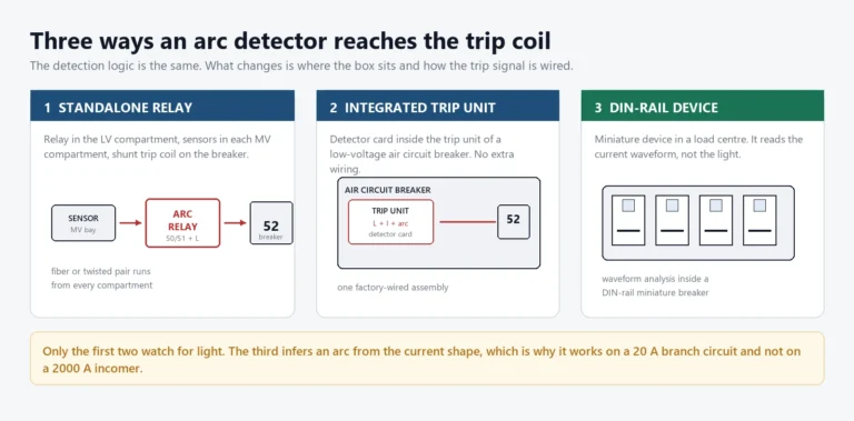
- ANSI device 52 is the switching device itself; the 50/51 elements in the relay only decide when it should trip.
- A unit rated 25 kA at 415 V is tested to interrupt 25 kA. A 36 kA fault welds contacts or bursts the arc chute.
- Trip curves B, C and D move the magnetic threshold from 3 to 5, 5 to 10 and 10 to 20 times rated current.
- Vacuum interrupters dominate 1 kV to 40.5 kV. SF6 stays common above 72.5 kV, where vacuum bottles get expensive.
- An Ics below 75 percent of Icu means one full fault current and the device goes to scrap.
- Type 2 coordination to IEC 60947-4-1 permits contact welding after a fault. Type 1 does not permit any damage.
- Circuit breakers that trip on motor inrush have a setting fault, not a hardware fault.
What circuit breakers do at the point of fault
One device in a switchgear cubicle is expected to open a fault current and close again afterwards. A switch-disconnector isolates, a fuse interrupts once and then needs replacing, a contactor switches load but cannot clear a short circuit, and a circuit breaker does all three jobs on demand, repeatedly, for twenty years.
The distinction matters at factory acceptance.
An inspector who accepts a switch-disconnector where a breaker was specified leaves the panel with no means of clearing a terminal fault. The isolator has no arc-control chamber sized for 25 kA. Closing it onto a fault is a fault-throw operation, and the cubicle door is the only barrier left.
| Device | Clears fault current | Reusable after a fault | Governing standard |
|---|---|---|---|
| Switch-disconnector | No, load current only | Yes | IEC 60947-3:2015 |
| Fuse | Yes, once | No, element replaced | IEC 60269-1 |
| Contactor | No, overload current only | Yes | IEC 60947-4-1:2023 |
| Air circuit breaker | Yes, within rated short-circuit capacity | Yes | IEC 60947-2:2016 |
| Vacuum or SF6 breaker | Yes, within rated short-circuit current | Yes | IEC 62271-100:2021 |
Table 1. Four switching devices that share a cubicle, and the one column that separates them.
Interrupting capacity is the number that separates the rows above.
A 630 A molded-case device with an Icu of 25 kA at 415 V will carry 630 A indefinitely and clear 25 kA for the duration of one test sequence. Feed a 36 kA fault into it and the contacts part, the arc does not extinguish at current zero, and the pressure inside the case finds the weakest joint. That failure is not a nuisance trip. It is a busbar fault that started inside the device.
How the arc is extinguished at the contacts
Every fault interruption is an arc that has to be cooled below the ionisation threshold before the next current zero arrives. At 50 Hz a current zero comes every 10 ms, so the arc-control system has one half-cycle to raise the gap dielectric strength above the recovery voltage, or the arc restrikes and the sequence starts again.
Air and molded-case devices use splitter plates. The arc is driven magnetically into a stack of steel plates, stretched, cooled and divided into short arcs whose combined voltage exceeds the recovery voltage. Current-limiting cases add a U-shaped loop that pushes the arc sideways, so the fault is cut at 3 to 5 kA of prospective current instead of waiting for the natural zero at 25 kA.
Vacuum bottles interrupt at the cathode spots. Contact parting draws a metal-vapour arc that stays diffuse until the current falls below roughly 100 A, then chops. Dielectric recovery is fast, contact travel is 8 to 12 mm, and the bottle seals for life. Nothing vents outside the bottle, which is why vacuum units suit indoor metal-clad switchgear at 11 kV and 33 kV.
SF6 designs rely on gas density. The arc burns in an atmosphere at 0.4 to 0.6 MPa, and the nozzle shapes a gas flow that cools the arc column at the zero crossing. Interrupting capability scales with pressure, so a low-density alarm at minus 10 percent must force a lockout. Operating an SF6 breaker below its density curve is how a 40 kA unit becomes an exploding chamber.
Look at the nameplate before the type test report. The interrupting medium tells you the maintenance interval, the space it needs and the failure mode you will meet in year fifteen.
Ratings that decide whether a device survives
Four numbers on a low-voltage nameplate carry almost all the risk, and three of them are routinely misread during procurement. The table below is the check list we use when a client sends a panel schedule for review.
| Rating | What it means | Typical value at 415 V | What goes wrong when it is misread |
|---|---|---|---|
| Icu, rated ultimate short-circuit capacity | Highest fault current the device can interrupt once | 25 kA to 70 kA | Device is destroyed after clearing, which is allowed by the standard |
| Ics, rated service short-circuit capacity | Fault current it can interrupt and then keep working | 50 to 100 percent of Icu | Panel is restored after a fault and trips again on the next start |
| Icw, rated short-time withstand | Current it carries for 1 s without tripping, for selectivity | 20 kA to 65 kA for 1 s | Upstream and downstream devices trip together; selectivity claim collapses |
| Icm, rated short-circuit making capacity | Peak current it can close onto without welding | 2.1 times Icu at 50 Hz | Contact welding on a close-onto-fault, mechanism jammed |
Table 2. The four short-circuit ratings on a low-voltage nameplate, and the consequence of swapping one for another.
Icu without Ics is half a specification.
Two devices can both show 36 kA and behave nothing alike after the event. A unit with Ics at 100 percent of Icu is ready to reclose. A unit with Ics at 50 percent is a one-shot device at 36 kA, and the panel schedule will not say so. Ask for both figures in writing, then check that the cascade table used for the panel actually lists the Ics of the downstream device, not the Icu.
Utilization category sets the duty. AC-3 covers motor starting and stopping with inrush at 6 to 8 times rated current; AC-1 covers resistive loads. A contactor or breaker selected on AC-1 numbers and applied to a pump will erode its contacts in months. The same logic runs on the breaker side: circuit breakers specified for AC-3 duty carry an electrical life rating measured in operations at 6 times In, not at In.
Temperature derating is the quiet one. A 630 A frame in a cubicle at 55 degrees Celsius inside the enclosure carries roughly 560 A, because the nameplate number assumes 40 degrees ambient and free air. Sealed outdoor kiosks in the Gulf run hotter than that in July, so the derating curve, not the nameplate, decides the frame size.
Trip curves and the margin to motor inrush
A time-current curve has two halves, and buyers read the wrong half. The thermal half, below the magnetic threshold, is where overload protection lives and where seconds matter. The magnetic half above the threshold is where the device must open in tens of milliseconds, and the curve there behaves like a vertical wall.
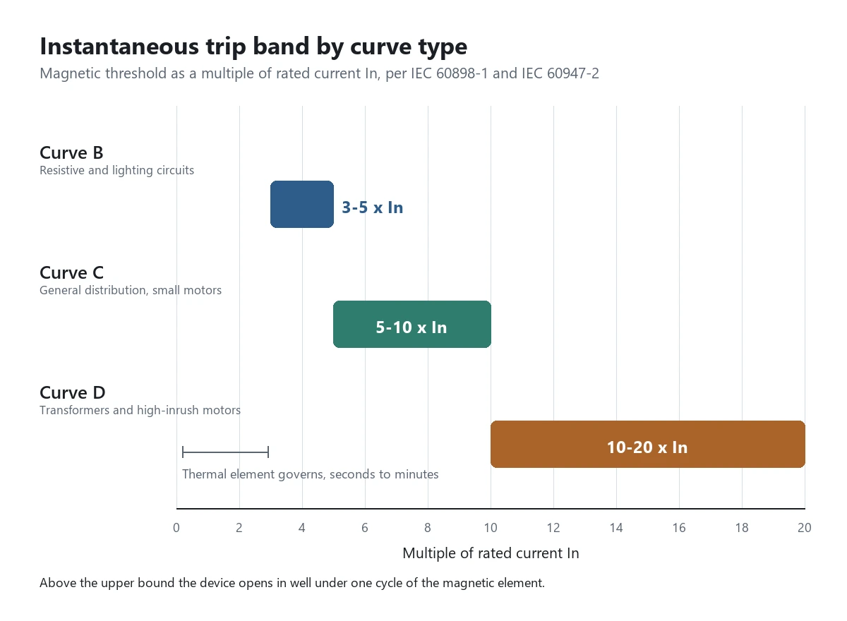
Circuit breakers are chosen against inrush before they are chosen against load. Curve B opens between 3 and 5 times In, curve C between 5 and 10, curve D between 10 and 20. A motor that starts at 7 times In lands inside the curve C band, so the magnetic element fires on every start and the operator logs nuisance trips. The fix is a curve D case, or the next frame up with the same curve letter and more thermal headroom, not a bigger cable.
Harmonics raise the effective thermal load without touching the magnetic threshold, which is why a board that trips at night on lighting loads points at the thermal element first. Log the current for a full day before changing a curve letter.
LV, MV and HV families in practice
Five families of circuit breakers cover the range from a distribution board to a 400 kV substation, and each one has a voltage band where it wins on cost. Choosing the family first, and the rating second, saves a redesign later.
| Family | Voltage band | Typical rating | Where it is the right answer |
|---|---|---|---|
| MCB, miniature | 230 V to 415 V | 6 A to 125 A, 10 kA | Final circuits, lighting and socket outlets, IEC 60898-1:2015 |
| MCCB, molded case | 415 V to 690 V | 16 A to 1600 A, 25 kA to 70 kA | Feeder and motor circuits in LV switchboards |
| ACB, air circuit | 415 V to 690 V | 630 A to 6300 A, 50 kA to 100 kA | Main incoming and bus-coupler, where selectivity is required |
| VCB, vacuum | 1 kV to 40.5 kV | 630 A to 4000 A, 20 kA to 50 kA | 11 kV and 33 kV feeders, motors, transformers |
| SF6 or GIS | 72.5 kV and above | 1250 A to 4000 A, 31.5 kA to 63 kA | Transmission substations and compact indoor HV |
Table 3. Five device families, the voltage band each one owns, and the application where it beats its neighbours.
Voltage class, not current, drives the family choice.
An 11 kV feeder at 400 A needs a vacuum unit even though a 630 A molded-case device would carry the current. The insulation distance at 11 kV is 75 mm in air, and no molded case gives you that. Conversely, a 690 V feeder at 1600 A belongs in an air circuit breaker, because a vacuum bottle at that current costs three times as much and buys nothing.
Ring main units sit between the families. A four-way RMU at 11 kV uses a vacuum interrupter for the circuit position and a simple switch-disconnector for the ring positions, which is why an RMU can isolate a ring cable but cannot clear a downstream feeder fault on its own. Protection for that arrangement is a separate engineering task, covered in our note on RMU protection relay settings.
Where circuit breakers stop and the relay starts
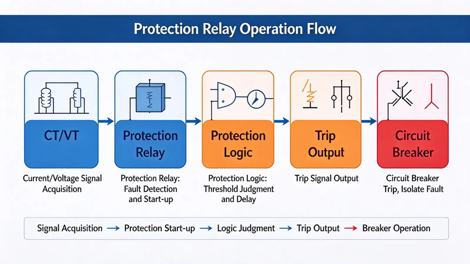
Two devices share the trip decision, and confusing their roles produces panels that trip correctly in test and fail in service. The breaker interrupts; the relay measures. Neither one is a substitute for the other, and no breaker contains a protection function that a relay cannot override.
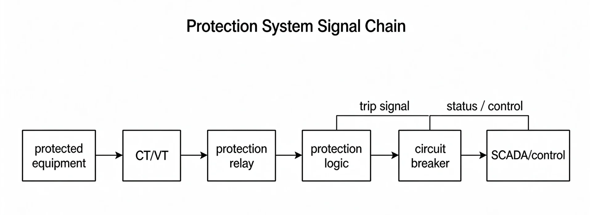
ANSI/IEEE C37.2-2022 assigns device 52 to the AC circuit breaker itself. The overcurrent elements that command it are 50 for instantaneous and 51 for time-delayed, and 50BF covers breaker failure. A scheme drawing that puts 52 inside the relay boundary is wrong in a way that survives review, because the numbers look familiar.
Three signals cross the boundary and each one needs a check at commissioning.
The trip output is a wet or dry contact from the relay into the breaker’s trip coil, typically 24 V DC or 110 V DC at 2 A to 5 A. Coil resistance at 110 V DC sits near 60 to 120 ohms, so a 2.5 mm cable over 200 m adds enough loop resistance to drop the coil voltage below its minimum pick-up. The breaker then refuses to trip on a real fault while passing every secondary injection test, because the test set injects into the relay and never sees the coil.
The 52a and 52b auxiliary contacts report position. They are mechanical, they wear, and a stuck 52a contact makes the breaker-failure logic believe the device never closed. That produces either a spurious 50BF trip of the upstream incomer or a dead trip that nobody notices until the next fault.
ANSI 86 lockout is the third path. A trip from 86 blocks closing until an operator resets it by hand, which is the correct behaviour after a differential or Buchholz operation and the wrong behaviour after a downstream feeder fault. Wiring 86 into the incomer trip without separating the two cases is a common cause of a whole board going dark for a single motor fault.
Selection matrix: matching the device to the duty
Six questions settle the device type before any catalogue is opened, and the order matters because a later answer can invalidate an earlier one. Work down the table, not across it.
| Question | If yes | If no | Number to check |
|---|---|---|---|
| Is the system voltage above 1 kV? | Vacuum or SF6 family, IEC 62271-100:2021 | Molded case or air family, IEC 60947-2:2016 | Um, rated maximum voltage |
| Does the load start at 6 to 8 times In? | Motor duty, AC-3, check electrical life at 6 In | Distribution duty, AC-1 numbers apply | In and locked-rotor current |
| Is selectivity with the upstream device required? | Need Icw and an adjustable short-time delay | Fixed instantaneous is acceptable | Icw for 1 s |
| Is the prospective fault above 25 kA? | Check Ics, not only Icu, and cascade data | Standard 25 kA frame is enough | Icu and Ics together |
| Will the device be operated daily? | Mechanical life above 20,000 operations | Isolation duty, life rarely binds | Mechanical endurance figure |
| Is the enclosure sealed and hot? | Apply the derating curve before sizing | Nameplate current stands | Ambient inside the cubicle |
Table 4. Six questions in the order that avoids rework, with the number that decides each answer.
Matching a device to duty is quicker than comparing catalogue pages.
When the answers point to a molded-case device but selectivity is also required, the compromise is a frame with an adjustable short-time delay and an Icw rating, not a bigger frame. A 250 A frame with 1 s Icw at 20 kA coordinates with a 630 A incomer; a 400 A frame with instantaneous-only protection does not, whatever its Icu says.
For panels where the breaker and the relay are supplied together, the function list matters more than the frame size. Our switchgear controller page lists the 50/51, 50BF and 86 combinations we assemble for feeder and incomer positions.
Coordination with relays, fuses and upstream devices
Selectivity is a promise about which device opens first, and it holds only for the fault range it was calculated over. Two circuit breakers in series are selective at 3 kA and simultaneous at 12 kA more often than panel schedules admit.
Time selectivity is the simplest form. The downstream relay has a 0.3 s grading margin over the upstream one, which covers the breaker opening time of 50 ms to 80 ms, the relay overshoot of 20 ms to 40 ms and the CT error. Anything below 0.25 s of margin is arithmetic, not engineering.
Current selectivity works where the downstream device has a lower instantaneous threshold than the upstream one. Energy selectivity works in the current-limiting region, where the downstream device clears before the upstream one sees the peak. Mixing the three in one board without a coordination study is how a feeder fault takes out the incomer.
Type 1 and Type 2 coordination to IEC 60947-4-1 decide what is allowed to happen to the contactor and the breaker after a fault. Type 2 permits welding of contactor contacts provided they can be separated by hand, and requires no damage to the breaker or the overload relay. Type 1 permits damage, provided the devices are safe to repair. Motor starters on pumps usually specify Type 2, because a welded contactor in a remote pump station is a call-out.
Fuses and breakers coordinate differently. A fuse is fast at high current and slow at low overcurrent; a breaker with a thermal-magnetic trip is the reverse. Placing a 100 A gG fuse upstream of a 63 A breaker gives selectivity up to about 2 kA and none above it, because the breaker’s instantaneous element fires first. The crossover current is the only number worth checking, and the manufacturer’s selectivity table gives it directly.
When circuit breakers are the wrong device
Four situations come up in review meetings and none of them ends well when the breaker is forced into the role. Each one has a different correct answer, and the cost of getting it wrong lands on the commissioning team.
- Isolation for work on a live board. A breaker has no visible break and no lockable isolation position, so IEC 60947-3 requires a separate switch-disconnector or a withdrawable truck with a defined test position.
- Earth leakage protection. Residual current is a measurement function; a breaker with a 30 mA module is an RCBO, and a plain breaker plus earth fault relay is not the same device for personnel protection.
- DC circuits without a DC rating. An AC-rated device at 250 V DC may have an interrupting capacity of a few hundred amps, because the arc does not see a natural current zero. DC rating is a separate test and a separate number.
- Frequent switching duty. A breaker rated for 10,000 mechanical operations and used as a daily load switch in a pump station reaches its endurance in three years, and the contacts erode long before the mechanism wears out.
Each item above is a scope error rather than a product defect.
A withdrawable truck solves the isolation case without adding a device, provided the panel has a defined test position and the door interlock is functional. The other three need a different component, and no amount of setting work will convert one into the other.
Failure modes seen in the field
Five failure patterns account for most of the circuit breakers we attend, and four of them are visible during a routine inspection. The fifth is electrical and hides behind a passing test.
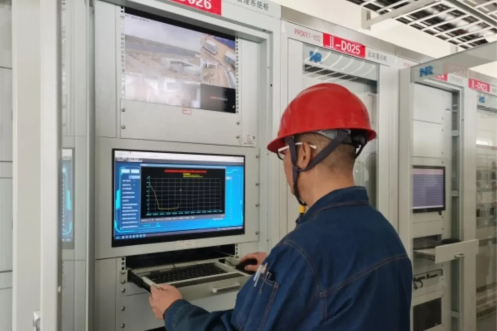
Contact welding is the first. A close-onto-fault at a current above Icm welds the tips, and the mechanism then holds the breaker closed while the upstream device clears. The cause is usually a spring-charge sequence that closed before the fault was cleared, not a defective contact.
Arc chute erosion is the second. Splitter plates erode from the top edge down, and after 30 to 50 full faults the gap between plates is wide enough that the arc restrikes. A routine inspection that measures plate thickness catches this; a trip test at 2 kA does not.
Trip coil burnout is the third. A coil rated for intermittent duty and energised continuously burns in minutes, and the breaker becomes a dead trip that still shows correct position. Measuring coil resistance at commissioning and again at the first annual service finds it before a fault does.
Mechanism sticking is the fourth, and it appears after long idle periods. Grease hardens, the latch does not release, and the breaker refuses to open. Exercise every breaker twice a year, and the problem disappears for the cost of a switching schedule.
SF6 density drift is the fifth. The gauge reads normal until the density switch operates at the alarm level, and by then the interrupting capability is already below rating. Density, not pressure, is the quantity to log, because pressure moves with temperature and a cold morning looks like a leak.
Conclusion
Circuit breakers are only as good as the two numbers behind their selection: the fault level at their terminals and the duty they will actually see. Get the interrupting capacity above the prospective fault, confirm Ics rather than stopping at Icu, and check the utilisation category against the load. Everything else on the nameplate is detail that follows.
Then verify the trip path, not just the trip logic. Secondary injection into the relay proves the algorithm and the settings. It does not prove the coil, the 52a contact or the mechanism, and those three are where the panel actually fails.
Frequently asked questions
What is the difference between Icu and Ics?
Icu is the highest fault current the device can interrupt once, after which it may be destroyed. Ics is the current it can interrupt and then continue to carry rated current, so it defines whether the panel can be restored after a fault. Ics is usually between 50 and 100 percent of Icu.
How do I choose between B, C and D trip curves?
Match the magnetic threshold to the inrush of the load. Curve B trips at 3 to 5 times rated current and suits resistive and lighting circuits. Curve C trips at 5 to 10 times and covers general distribution and small motors. Curve D trips at 10 to 20 times and suits transformers and large motors with high starting current.
Can a circuit breaker be used as an isolator?
Not for work on a live board. A fixed breaker gives no visible break, so IEC 60947-3 requires a separate switch-disconnector or a withdrawable truck with a defined test position. A withdrawable truck satisfies the isolation requirement without adding a second device in the circuit.
Why does a breaker trip when there is no fault?
Three causes dominate: motor inrush above the magnetic threshold, a harmonic current heating the thermal element, or a shared neutral returning current through the wrong pole. Check the actual starting current with a recorder before changing the curve, and check the neutral wiring before changing the device.
What does 25 kA on a breaker actually mean?
It means the device was tested to interrupt a prospective fault current of 25 kA at its rated voltage, for one test sequence. The figure is not a continuous rating and it is not a safety margin. A fault above 25 kA at the terminals exceeds the device’s tested capability.
Do I need a breaker if I already have a protection relay?
Yes. The relay measures and decides, and the breaker interrupts. A relay without a breaker has no way to open the circuit, and a breaker without a relay has no way to detect a fault in time. The two are a pair, joined by the trip coil and the 52a status contact.
How often should a breaker be tested?
Exercise every breaker twice a year, and run a contact resistance test at the annual service. A full timing test at rated short-circuit current is a type test, not a routine one. Most operators rely on inspection, contact resistance and trip coil resistance between major overhauls.
Related reading
- Protection schemes for switchgear, covering what sits around the breaker in a metal-clad board.
- Short-circuit protection relays, for the 50 element that commands the trip.
- Setting 50/51 overcurrent elements, including the grading margin calculation.
- Nuisance tripping, when the breaker opens without a fault.
Sources and standards
| Source | What it covers | Type | Edition |
|---|---|---|---|
| IEC 60947-2:2016 | Low-voltage circuit-breakers: ratings, tests, utilisation category | Standard | 2016 |
| IEC 60947-1:2020 | General rules for low-voltage switchgear and controlgear | Standard | 2020 |
| IEC 60947-3:2015 | Switches, disconnectors and fuse-combination units | Standard | 2015 |
| IEC 60947-4-1:2023 | Contactors and motor-starters, Type 1 and Type 2 coordination | Standard | 2023 |
| IEC 62271-100:2021 | AC circuit-breakers above 1 kV: rating and test procedure | Standard | 2021 |
| IEC 62271-1:2017 | Common specifications for high-voltage switchgear | Standard | 2017 |
| ANSI/IEEE C37.2-2022 | Device function numbers, including 52, 50, 51, 50BF and 86 | Standard | 2022 |
| IEEE C37.04-2018 | Rating structure for AC high-voltage circuit-breakers | Standard | 2018 |
| IEEE C37.010-2016 | Application guide for AC high-voltage circuit-breakers | Standard | 2016 |
| IEC 60898-1:2015 | Miniature circuit-breakers for household and similar installations | Standard | 2015 |
Table 5. Standards referenced above, with the edition each figure in this guide was taken from.
Field figures in this guide come from our own commissioning records on 415 V and 11 kV boards, 2023 to 2026. They describe what we measured on those panels and nothing beyond them.
About Author

Hello, I'm Leno Zhang. I have 15 years of experience in the power relay protection industry with extensive pre-sales and after-sales project experience. Our company specializes in various complete sets of relay protection and automation equipment. I can assist customers in solving all practical on-site project challenges and provide optimal integrated solutions.
Tell Us Your Requirement
High Quality
Stable performance, reliable design, ensuring safe operation for power system protection and grid stability.
Fast Delivery
Timely delivery to support your urgent orders and project schedules efficiently and professionally at any time.
Best Warranty
Professional Warranty: Reliable after-sales support for stable relay protection and long-term customer satisfaction.