
-
Leon Zhang sales consultant
-
Email: zxl635973785@gmail.com
-
Phone/WhatsApp: +86 13655813266
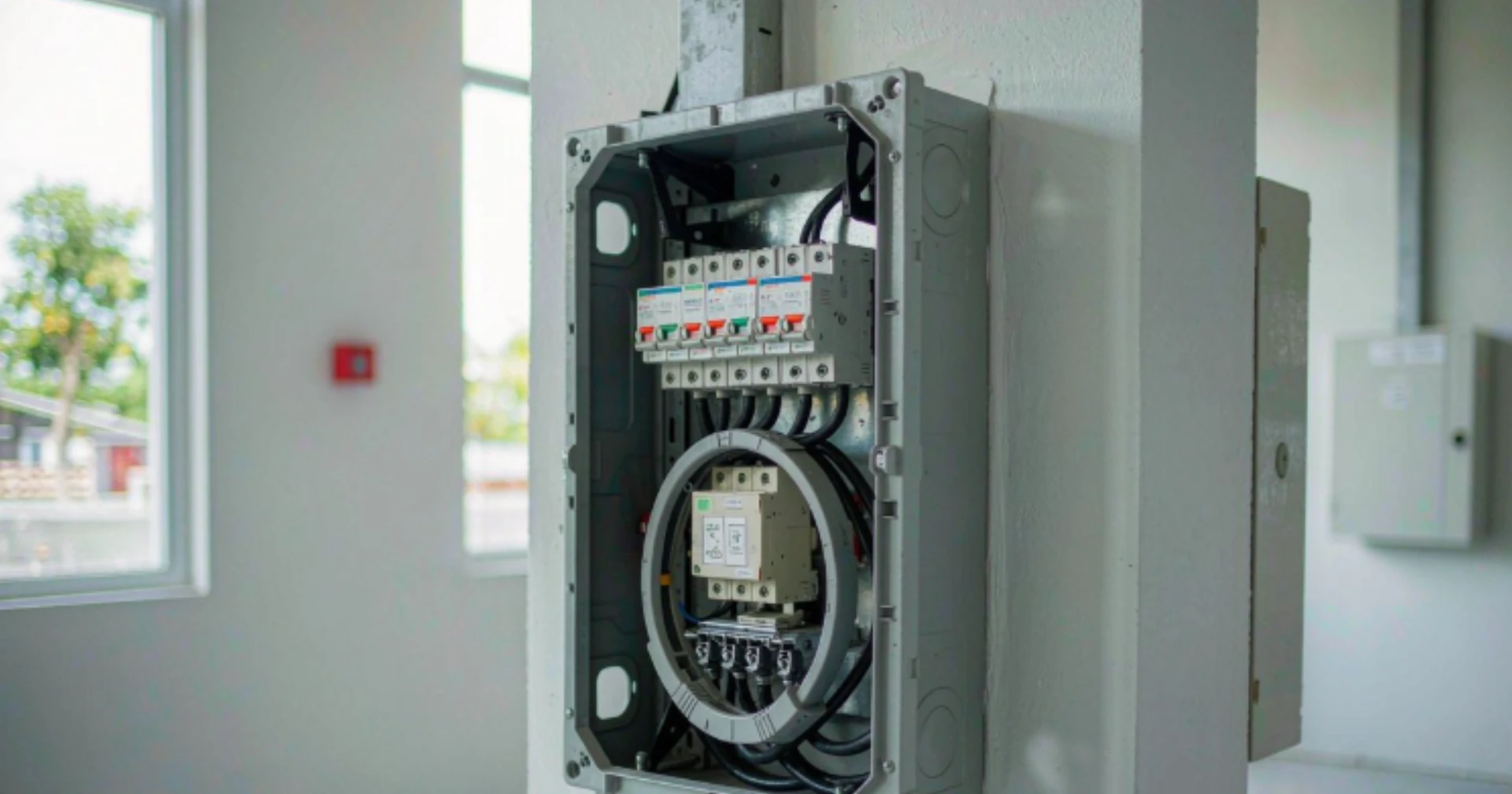
Earth Leakage Relay Philippines: A Practical Guide
An earth leakage relay measures the vector sum of current in every live conductor and closes a contact when that sum leaves zero. Philippine selection turns on the PEC 4 to 6 mA shock limit, the residual current Type and a 60 Hz nameplate rating.
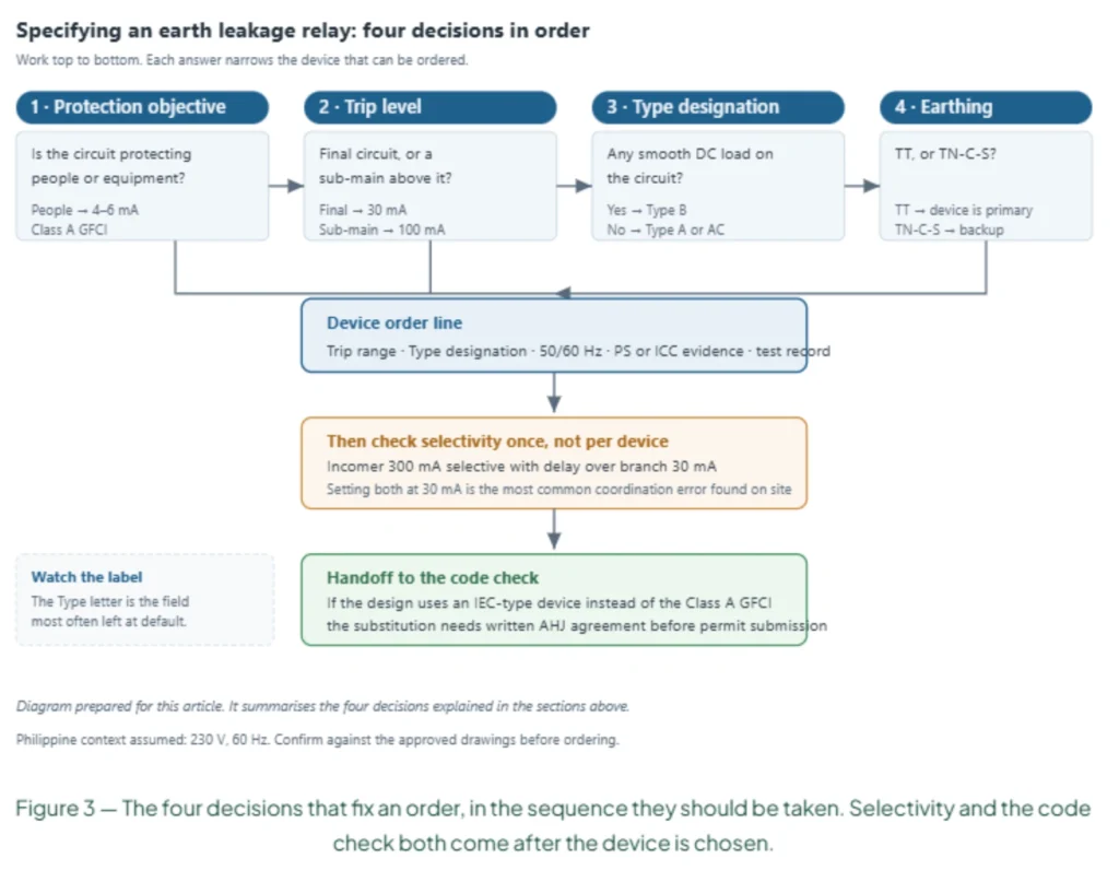
Earth leakage relay Philippines selection comes down to four variables: protection objective, residual current Type, earthing arrangement and rated frequency. The relay measures the vector sum of current in every live conductor through a core balance CT and closes a contact when that sum leaves zero.
The Type letter is where Philippine projects go wrong. IEC 60755:2017 defines Type AC, A, F and B by the residual current waveform each one detects. A rooftop inverter puts smooth DC on the circuit, and a Type AC core cannot see it at all.
At a Glance
- PEC 2017 sets personnel protection at 4 to 6 mA Class A, not the 30 mA that IEC practice uses.
- A 30 mA device is not an automatic substitute for a Class A GFCI; the building official decides.
- The Philippine supply is 230 V at 60 Hz per PNS 1572:1997, and a 50 Hz-only device drifts off curve.
- Type AC sees sinusoidal AC only. Type B adds smooth DC from inverters, drives and EV chargers.
- IEC 61008-1:2024 covers RCCBs to 125 A on 50 Hz, 60 Hz and 50/60 Hz systems.
- Cable capacitance adds roughly 1.5 mA of standing leakage per 100 m at 230 V.
- Keep continuous leakage below 30 percent of the rated residual operating current, or expect trips.
- TT earthing makes the relay the primary protection. TN-C-S usually leaves it as backup.
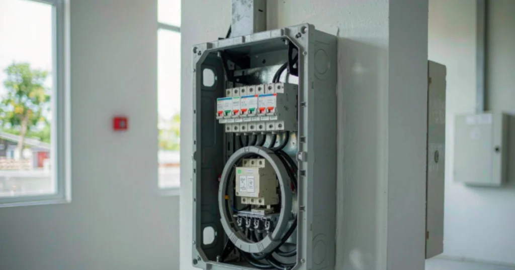
Earth Leakage Relay Philippines: What the Device Does and Does Not Cover
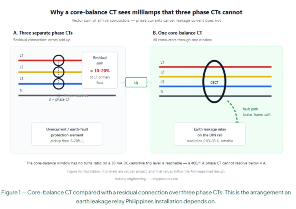
An earth leakage relay Philippines switchboards carry is a measuring element, not a switch. The core balance CT encircles every live conductor, and its secondary carries the residual current itself rather than a scaled phase current.
Under normal conditions, current leaves the source and returns through the neutral. The net sum is zero. When insulation fails or a person touches a live part, some of that current returns through earth instead. The CBCT sees the difference.
A dry contact is the output. Disconnection belongs to a breaker, a contactor or a shunt release downstream. That split is the most misread point in a Philippine panel specification, because a relay that senses correctly and cannot prove its trip path detects a fault and does nothing about it. An RCCB, an RCBO and a Class A GFCI each combine sensing and interruption in one housing at a fixed threshold. The panel relay keeps the two apart, which is why the same hardware can be set to 30 mA on one board and 300 mA on the next.
| Device | Sensing method | Output | Trip mechanism | Typical application |
|---|---|---|---|---|
| Earth leakage relay (panel-mounted) | External CBCT | Isolated contact | External breaker or shunt | Industrial switchboards, MCCs |
| RCCB | Integral toroid | Direct mechanical | Integrated | Final circuits, DIN rail |
| RCBO | Integral toroid | Direct mechanical | Integrated plus overcurrent | Final circuits with overload protection |
| Class A GFCI | Integral toroid | Direct mechanical | Integrated | Receptacles per PEC 2017 |
Table 1. Where the panel relay sits relative to the all-in-one devices it gets confused with.
Earth Leakage Circuit Layout: Where the CBCT Goes
The earth leakage circuit starts at the CBCT window. Every live conductor passes through, including the neutral on a three-phase four-wire supply. The protective earth conductor stays outside. A neutral that bypasses the window is the most common wiring fault on Philippine distribution boards. The relay then sees a permanent standing offset, and it either will not trip or will not stay closed. A protective conductor routed through the window cancels normal leakage along with fault current. The device goes quiet exactly when it should operate.
On a 400/230 V four-wire board the neutral carries the unbalance current of the whole installation. Size the window for four conductors, not three.
Earth Leakage Relay Philippines Settings by Protection Objective
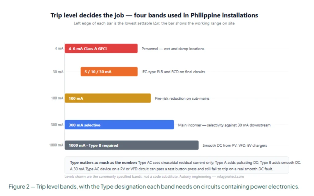
An earth leakage relay Philippines sub-mains carry usually sits at 100 mA or 300 mA. The 30 mA figure belongs to final circuits and to additional protection, not to an incomer feeding forty electronic loads.
PEC 2017 Article 2.10.1.8 names Class A GFCI protection at 4 to 6 mA for receptacles in bathrooms, kitchens, outdoor locations, garages, crawl spaces and laundry areas, and within 1.8 m of a sink. The 4 to 6 mA figure sits at the cardiac threshold, an order of magnitude below 30 mA. IEC practice treats 30 mA as additional protection, a backup where exposure is assumed brief rather than the primary safeguard.
Equipment protection starts at 100 mA. At 300 mA the objective has already changed from shock prevention to catching insulation degradation before it becomes ignition. Selective coordination needs a current ratio and a time delay working together. Upstream settings should exceed downstream ones by more than two to one, and the upstream device waits. Leakage accumulates slowly as insulation ages, so an incomer can cross its threshold before a branch fault grows large enough to trip.
| Protection objective | Rated residual operating current | Basis |
|---|---|---|
| Personnel, PEC receptacles | 4 to 6 mA | PEC 2017 Article 2.10.1.8, Class A |
| Personnel, additional protection | 30 mA | IEC practice, brief exposure |
| Equipment, sub-mains | 100 mA | Accumulated normal leakage |
| Fire risk, incomer | 300 mA or higher | Insulation degradation before ignition |
| Incomer with downstream devices | 300 mA with time delay | Ratio above 2:1, grading by time |
Table 2. Setting bands by objective, with the clause or practice behind each one.
Residual Current Waveform: Why Type Matters
Type designation decides which residual current waveform the device can detect at all. Two devices carrying the same 30 mA label behave differently on one circuit once power electronics appear.
IEC 60755:2017 sets the classification. Type AC responds to sinusoidal alternating residual current. Type A adds pulsating DC from single-phase rectifiers. Type B adds smooth DC, the component produced by three-phase rectifiers with a DC link. Type F covers mixed-frequency residual current from single-phase inverters. A type mismatch is not a nuisance trip. Smooth DC saturates the sensing core, and a saturated core loses sensitivity to genuine AC faults as well. The test button will not show it, because the button injects an internally generated AC signal.
The Type letter is also the field most often left at its default. A board that fed only lighting and sockets when it was built can end up feeding a rooftop inverter five years later, and nobody reopens the original line item.
| Load type | Required device Type | Reason |
|---|---|---|
| Resistive and linear loads | Type AC | Sinusoidal AC only |
| Single-phase electronics, socket circuits | Type A | Pulsating DC residual current |
| VFDs, solar inverters, EV chargers, UPS with DC link | Type B | Smooth DC residual current |
| Mixed-frequency loads | Type F | Single-phase inverter leakage |
Table 3. Load type against the device Type that can actually see the leakage it produces.
Ground Relay or Earth Leakage Relay: How the Roles Differ
A ground relay and an earth leakage relay both look at current that should not be there, and the two names get used as if they were one device. They are not, and the difference is measured in decades of magnitude.
A ground relay is an overcurrent element. ANSI/IEEE C37.2-2022 gives it device numbers 50G and 51G for the instantaneous and time-delayed functions, measuring current in the neutral-to-earth path or the residual connection of three phase CTs. Pick-up is expressed in amps, commonly 10 to 20 percent of rated current on a solidly earthed system. An earth leakage relay works in milliamps and answers a different question. Device 64 is the ground protective function, and that is the family where the concern is touch voltage or fire rather than fault magnitude. Where the sensing element sits inside a wider scheme, the measurement principle is the same one described in our guide to how protective relays work.
One Philippine board can carry both. A 51G element at the transformer neutral handles phase-to-earth faults in amps, and 30 mA devices sit on the final circuits to cover shock risk. They grade against each other by current and time, and neither replaces the other.
| Function | ANSI device | Pick-up range | What it clears |
|---|---|---|---|
| Ground instantaneous overcurrent | 50G | Amps, 20 to 100 percent of rating | Phase-to-earth faults, high magnitude |
| Ground time overcurrent | 51G | Amps, 10 to 20 percent of rating | Sustained earth faults, graded by time |
| Ground protective | 64 | Milliamps to amps | Touch voltage, fire risk, high-impedance faults |
| Restricted earth fault | 87N | 5 to 10 percent of rating | In-zone winding and busbar earth faults |
Table 4. The ground fault family, with the device number and pick-up band that separates each function.
Core Balance CT Selection
Window size is mechanical first and electrical second. Dimensions across the range run from 33 by 23 mm to 450 mm diameter, covering network currents from 1 A to 4,000 A.
A split-core unit clamps around an existing bundle, so the window has to clear the bundle with the clamp open. That needs more room than the closed diameter suggests. A solid-core unit threaded during first wiring can use a smaller window for the same conductor count. Retrofit work is where the split-core version earns its cost. Cables stay connected, and the change happens in a planned outage window instead of a shutdown.
Accuracy class and burden matter less on a CBCT than on a metering CT, because the secondary feeds a relay input rather than an instrument. What does matter is the ratio error at the residual current you actually need to see. A window sized generously for future cables still has to resolve 30 mA on a 63 A circuit, and that is a question worth putting to the supplier in writing. Shielded cables change the picture slightly. Where a screen is earthed at both ends, part of the return current travels in the screen, so the screen has to pass through the window with the conductor it belongs to. Earthed at one end only, the screen stays outside. Getting this wrong on a drive feeder is a reliable way to produce a standing offset that no amount of setting adjustment will fix.

Ground Trigger Relay Outputs and Trip Circuit Proving
A ground trigger relay is the output half of the arrangement, the contact that fires the shunt release. Its rating has to match the trip coil, or the relay operates and the breaker stays closed.
Output contacts on panel relays are commonly rated 5 A at 250 V AC into a resistive load, and less into an inductive one. A shunt release coil is inductive. Check the coil inrush against the contact rating, then check the sealed current separately. Proving the trip path end to end is a commissioning test, not a drawing review. Inject residual current at the CBCT primary and confirm the breaker opens. A sensing test on its own says nothing about the wiring between the contact and the coil.
An interlock in series with the shunt release defeats the whole scheme while it is open for any other reason. Trip circuit supervision catches that condition, and it belongs in the specification rather than in a site instruction.
Earthing Arrangement Changes the Design
TN-C-S combines the supply neutral and the protective conductor for part of the route. Fault loop impedance is low, so an overcurrent device often clears an earth fault before the leakage relay reaches its threshold. The relay is backup, and it covers the high-impedance faults that overcurrent protection cannot see. TT is common where the installation has its own electrode and no metallic fault path back to the supply transformer. Fault loop impedance is high. The leakage relay becomes the primary protection, and electrode resistance becomes a design number rather than a site measurement.
The bound on electrode resistance works backwards from the setting. IEC 60364-4-41:2005 sets the touch-voltage limit at 50 V for ordinary locations and 25 V for earthed locations. Divide the permitted touch voltage by the rated residual operating current and the result is the largest loop impedance the scheme can tolerate. At 50 V and 300 mA that works out near 166 Ω for the whole loop, with the electrode carrying most of it. Electrode resistance is not a constant. It rises as soil dries and as the water table moves with the season.
A vendor who quotes a device without asking about the earthing arrangement has quoted half a specification. The distinction between the leakage element and a plain earth fault element is set out on our earth fault relay protection page.
Earth Leakage Relay Philippines Supply: 60 Hz Is Not Optional
PNS 1572:1997 defines the Philippine supply as 230 V with a tolerance of plus or minus 10 percent at a nominal 60 Hz. Frequency is a rating, and it decides whether a published trip curve means anything on site. The sensing core responds to how fast the residual current reverses. A core sized for 50 Hz presents different impedance at 60 Hz, so a 50 Hz-only device produces trip times that do not match its own data sheet.
The earth leakage relay Philippines projects receive is usually rated 50/60 Hz, and the nameplate is the only place to confirm it. Marketing copy says 50/60 Hz while the label says 50 Hz often enough to be worth thirty seconds with a camera.
Voltage tolerance matters for a second reason. A measuring circuit specified for a narrow band can misread residual current during a sustained low-voltage condition, and Philippine utilities apply the full plus or minus 10 percent band. An order should state the conductor configuration as well as the current rating.
Sustained overvoltage is the third supply condition worth naming in a specification. IEC 61008-1:2024 added requirements and tests for resistance to temporary overvoltages, which tells you the industry found the older designs wanting. On a board where the supply neutral is lost upstream, a 230 V circuit can sit well above nominal for hours, and a measuring circuit that survives that is worth asking for by name.
Nuisance Tripping: Causes and Mitigation
Intermittent tripping after handover is accumulated normal leakage far more often than a defective device. Cable capacitance alone contributes roughly 1.5 mA per 100 m at 230 V. EMC filter capacitors in electronic equipment add more, and drives add common-mode current through the motor winding and the cable capacitance. Schneider Electric Technical Guide CA908066E puts the practical limit at 30 percent of the rated residual operating current. On a 30 mA device that leaves 9 mA of standing leakage.
Splitting circuits reduces the load count behind each device. Measuring actual leakage before fixing a threshold beats guessing. Type B or Type F on circuits with power electronics removes the waveform problem instead of trading it for a higher setting.
Raising the setting on a personnel circuit is rarely the right answer. The setting that stops the tripping also raises the current a person carries before the circuit opens. For devices that trip without a genuine fault, our protection relay nuisance tripping guide walks through the same diagnostic sequence.
What to Include in an Earth Leakage Relay Philippines RFQ
A specification that says only earth leakage relay 30 mA will return three different quotations, because it leaves the Type, the earthing role and the physical envelope to the supplier’s judgement. An enquiry that can be priced and reviewed against approved drawings states the parameters below.
| Parameter | What to state | Why it matters |
|---|---|---|
| Protection objective | Personnel, equipment, or fire | Decides trip level and device type |
| System voltage and frequency | 230 V or 400 V, 60 Hz | Confirms device compatibility |
| Rated residual operating current | 30 mA, 100 mA, 300 mA, or adjustable range | Follows the objective and the coordination study |
| Type designation | AC, A, F, or B | Must match connected loads |
| Earthing arrangement | TT or TN-C-S | Decides primary or backup role |
| CBCT window size | Cable diameter or busbar dimensions | Physical installation constraint |
| Trip time | Instantaneous or delayed, with the delay stated | Required for selective coordination |
| Auxiliary supply | Voltage range | Decides availability on loss of supply |
| Output contact rating | Must match the shunt release or trip coil | Ensures the breaker actually opens |
| Test facility | Integral test button plus primary injection provision | Required for commissioning records |
| Certification | PS mark or ICC evidence where applicable | Customs release and market compliance |
Table 5. The eleven lines that turn an enquiry into a comparable quotation.
Earth Leakage Relay Philippines Compliance: PS Mark, ICC and AHJ Review
Locally manufactured products carry the PS mark. Imported products carry an Import Commodity Clearance, issued against the shipment rather than the model.
An earth leakage relay Philippines imports move under an ICC issued per consignment, so a clearance number from an earlier delivery does not cover a later one. The distinction matters twice: once at customs release, and again when the building official reviews the dossier.
Commissioning and Test Records
A leak device that has never been injected is an assumption, not a protection. Three tests belong in the record, and each one proves a different link in the chain. The first is a visual and wiring check with the board dead: every live conductor through the window, no protective conductor inside it, and the CT secondary terminated at the relay with the screen earthed at one end only. Photograph it. A photograph settles an argument eighteen months later in a way that a tick box does not.
The second is primary injection at the CBCT. Pass a known current through a test conductor threaded alongside the live conductors and confirm the relay operates within its stated band. If you inject 30 mA on a 30 mA device and it does not move, you have learned something that no amount of button pressing would have told you. The third is the trip path test. Operate the relay output and confirm the breaker opens, then confirm the auxiliary contact or SCADA indication follows. Record the operating time against the published curve, along with the ambient temperature, because a curve validated at 20 degrees is not the curve you get inside a switchroom in Cebu in May.
Standing leakage deserves a measurement of its own before the settings are fixed. Clamp a leakage meter on the circuit with the loads running and write the number down. That figure, more than any catalogue value, decides whether a 30 mA setting will survive its first week.
Frequently Asked Questions
Can a 30 mA earth leakage relay Philippines buyers order substitute for a Class A GFCI?
Not automatically. PEC 2017 Article 2.10.1.8 names Class A GFCI protection at 4 to 6 mA for personnel protection in listed locations. Substituting a 30 mA device is a deviation that needs written agreement from the Office of the Building Official before the permit drawings are final.
What CBCT window size do I need?
Measure the outside diameter of the cable bundle or the busbar cross-section, then add margin for installation. Split-core versions suit retrofit work where cables cannot be disconnected, and solid-core suits new wiring where the window only has to clear the conductors.
Why does the relay trip when a VFD starts?
A drive produces high-frequency common-mode leakage through the motor winding capacitance and the cable capacitance. A Type AC or Type A device reads part of that as a fault. A Type B device, or a drive-rated leakage relay, sees the waveform correctly and holds.
Does the earth leakage relay need a separate power supply?
Most panel-mounted relays need an auxiliary supply for the measuring circuit and the output contact. That supply is separate from the monitored circuit voltage, so confirm that the control power available in the panel falls inside the stated range before the order goes in.
What documentation should accompany a Philippine delivery?
Ask for a datasheet stating the rated residual operating current range, the Type designation, the auxiliary supply range and the nameplate frequency. Add PS mark or Import Commodity Clearance evidence where the product category requires it, since both are checked at customs release.
How often should earth leakage protection be tested?
Press the integral test button quarterly to prove the sensing path, and inject at the CBCT primary annually to prove the trip path. The button exercises the electronics only, so it will not reveal a broken trip coil, an open interlock contact or a neutral that bypasses the window.
How low does electrode resistance have to be on a TT supply?
Divide the permitted touch voltage by the rated residual operating current. At a 50 V limit and a 300 mA setting the whole loop can be about 166 Ω, and the electrode carries most of that. Measure it in the dry season, because the wet-season reading is the flattering one.
When an Earth Leakage Relay Is the Wrong Answer
Four situations put the device out of its depth, and each one can change the answer on a real project.
- Where the protective conductor is missing or degraded. The relay detects the fault and still leaves touch voltage uncontrolled during the fault interval.
- Where the fault produces no residual current, such as an open protective conductor with no simultaneous insulation failure.
- Where standing leakage is genuinely larger than the setting. Turning the threshold up until the tripping stops removes the protection the device was installed for.
- Where the fault is phase to phase. Residual current stays at zero and the relay never sees it, so overcurrent protection has to carry that duty.
Clause numbering in the PEC has also moved between editions. Verify the Article 2.10.1.8 and Article 2.30.7.6 references here against the edition your authority having jurisdiction enforces before they go into a submission.
Conclusion
Earth leakage relay Philippines selection comes down to four decisions in sequence. Define the objective first, personnel at 4 to 6 mA per PEC 2017 or equipment and fire risk at 100 to 300 mA. Match the Type to the loads on the circuit. Fix whether the relay is primary or backup from the earthing arrangement. Confirm the 60 Hz nameplate and the CBCT window.
Beijing Autony Electric builds numerical protection relays and protection and control panels for substations and industrial switchboards, and ships them to EPC contractors on Philippine projects. Every device leaves with a specification sheet stating the residual operating current range, the Type designation, the auxiliary supply range and the nameplate frequency. Where a project asks for a type test report, we provide it, and we say plainly when a specific report does not exist.
The field verification that follows uses the routine in our protection relay testing and commissioning guide, and the grading arithmetic follows the method in our protection relay setting calculation guide. Send the single-line diagram with the enquiry; the selection follows from the objective and the coordination study rather than a catalogue default.
Related Reading
- How protective relays work, the measurement principle behind every element on the board.
- Earth fault relay protection, where the 50G and 51G elements differ from leakage sensing.
- Relay protection for PV power systems, for the inverter leakage that breaks Type AC assumptions.
- Protection schemes for switchgear, for what sits around the device in a metal-clad board.
Sources and Standards
| Source | What it covers | Type | Edition |
|---|---|---|---|
| IEC 60755:2017 | General safety requirements for residual current operated protective devices, Type AC/A/F/B | Standard | 2017 |
| IEC 61008-1:2024 | RCCBs without integral overcurrent protection, to 125 A on 50 Hz and 60 Hz | Standard | 2024 |
| IEC 60364-4-41:2005 | Protection against electric shock, 50 V and 25 V touch-voltage limits | Standard | 2005 |
| IEC 60255-151:2009 | Functional requirements for over/under current protection | Standard | 2009 |
| IEC 60529:2013 | Degrees of protection provided by enclosures, IP code | Standard | 2013 |
| IEC 60947-2:2016 | Low-voltage circuit-breakers, ratings and test sequences | Standard | 2016 |
| ANSI/IEEE C37.2-2022 | Device function numbers, including 50G, 51G, 64 and 87N | Standard | 2022 |
| PEC 2017 | Philippine Electrical Code, Articles 2.10.1.8 and 2.30.7.6 | Code | 2017 |
| PNS 1572:1997 | Philippine supply voltage and frequency, 230 V at 60 Hz | Standard | 1997 |
| Schneider Electric CA908066E | Continuous leakage limit at 30 percent of rated residual operating current | Guide | 2022 |
Table 6. Every source referenced above, with the edition each figure was taken from.
Field figures in this guide come from our own commissioning records on 230 V and 400 V Philippine boards between 2023 and 2026. They describe what we measured on those panels and nothing beyond them.
About Author

Hello, I'm Leno Zhang. I have 15 years of experience in the power relay protection industry with extensive pre-sales and after-sales project experience. Our company specializes in various complete sets of relay protection and automation equipment. I can assist customers in solving all practical on-site project challenges and provide optimal integrated solutions.
Tell Us Your Requirement
High Quality
Stable performance, reliable design, ensuring safe operation for power system protection and grid stability.
Fast Delivery
Timely delivery to support your urgent orders and project schedules efficiently and professionally at any time.
Best Warranty
Professional Warranty: Reliable after-sales support for stable relay protection and long-term customer satisfaction.