

-
Leon Zhang sales consultant
-
Email: zxl635973785@gmail.com
-
Phone/WhatsApp: +86 13655813266
Capacitor Bank Unbalance Protection: Working Principle, Schemes and Relay Settings
Introduction
Capacitor bank unbalance protection is a core power system protection function designed to detect abnormal voltage and current asymmetry caused by damaged capacitor elements, failed units, or blown fuses in shunt capacitor banks. As a critical safeguard for reactive power compensation systems, it prevents cascading capacitor overvoltage damage, equipment burnout, and unplanned grid outages.
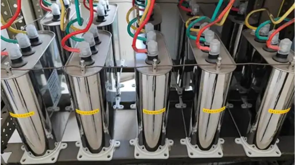
Most EPC contractors, substation operation and maintenance (O&M) engineers, and project owners search for targeted solutions to three core problems: the root causes of capacitor bank unbalance, accurate unbalance detection principles, and standardized relay setting rules.
This article delivers practical, industry-verified technical content covering unbalance generation mechanisms, detection principles, mainstream protection schemes, current/voltage detection logic, standardized relay settings, and post-fault operation workflows. All content complies with IEEE power system protection standards, providing actionable technical guidance for substation design, commissioning, and daily operation.
What Is Capacitor Bank Unbalance Protection?
Normal Capacitor Bank Condition
A healthy capacitor bank operates in a fully balanced three-phase state. All three phases feature consistent capacitance, equal operating current and phase voltage, zero neutral displacement voltage, and negligible neutral current. Under rated operating conditions, each capacitor unit bears uniform voltage stress, ensuring stable reactive power output and long-term safe operation.
What Happens When a Capacitor Unit Fails?
Capacitor bank unbalance originates from local capacitance deviation. Once individual capacitor elements or units fail or their fuses blow, the total capacitance of the corresponding phase drops, breaking the three-phase balance. This asymmetry generates unbalanced current and neutral offset voltage, which is captured and calculated by protection relays to trigger alarm or trip actions.
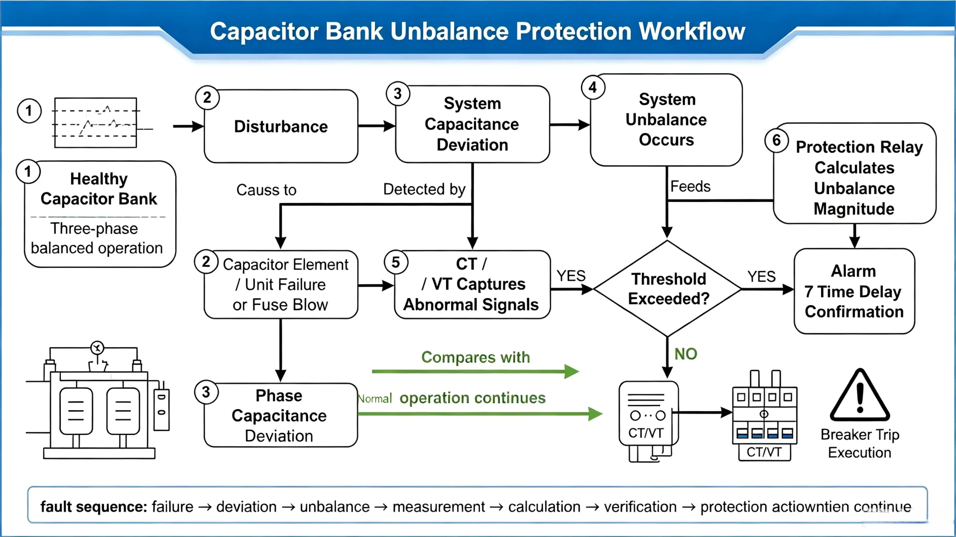
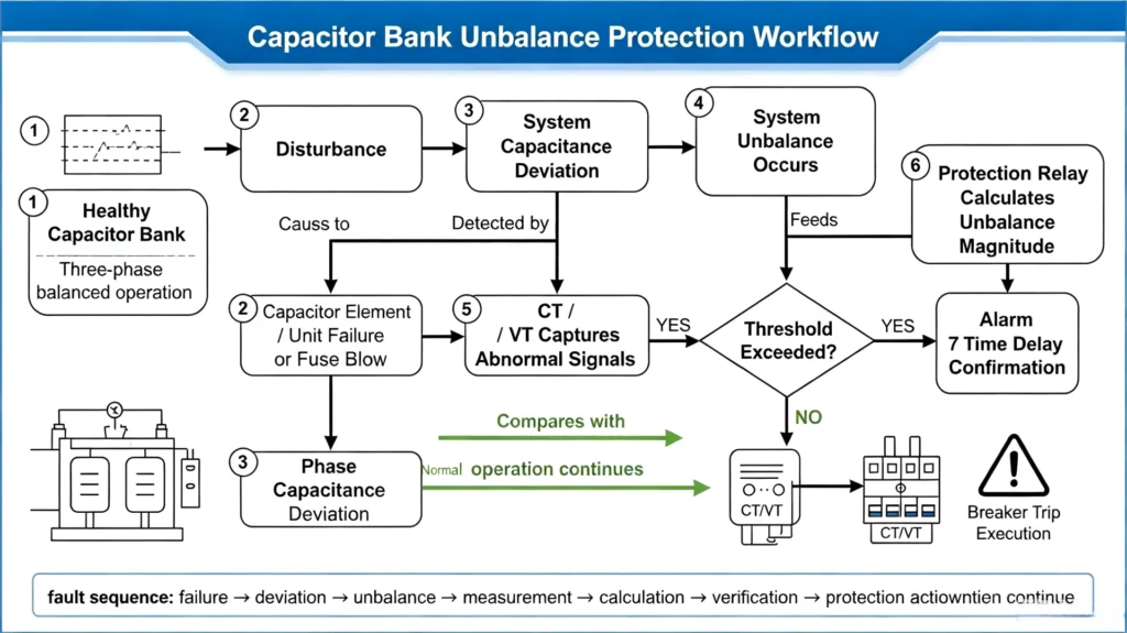
The complete fault evolution workflow is as follows:
Healthy capacitor bank → Three-phase balanced operation → Capacitor element/unit failure or fuse blow → Phase capacitance deviation → System unbalance occurs → CT/VT captures abnormal signals → Protection relay calculates unbalance magnitude → Threshold exceeded → Time delay confirmation → Alarm or breaker trip execution
A key professional distinction in power system operation is separating inherent natural unbalance and fault-related unbalance. Misjudgment of the two causes false protection actions or missed faults, which is the core basis for relay setting compensation.
Fault-Related Unbalance (Abnormal)
- Failed Capacitor Elements: Internal breakdown or aging of individual capacitor elements causes partial capacitance loss, forming subtle unbalance that is difficult for conventional overcurrent protection to detect.
- Failed Capacitor Units: Complete short-circuit or open-circuit failure of single capacitor units leads to obvious three-phase capacitance deviation, the main cause of severe unbalance faults.
- Blown Capacitor Fuses: Fuses blow to isolate faulty units during minor faults, resulting in phase capacitance reduction and unbalanced operating parameters.
- System Voltage Unbalance: Grid-side three-phase voltage asymmetry caused by load imbalance or line faults induces passive unbalance in capacitor banks.
How Does Capacitor Bank Unbalance Protection Work?
Unbalance protection relies on high-precision sensor sampling and relay algorithm calculation. It captures tiny current and voltage deviations caused by capacitance changes, filters normal system fluctuations through fixed time delays, and accurately identifies genuine capacitor faults. The complete technical workflow is standardized as follows:
Capacitor Bank Operation → Unbalance deviation occurs after unit/element failure → CT/VT real-time signal acquisition → Protection relay unbalance algorithm calculation → Compare with preset pickup threshold → Confirm duration exceeds time delay threshold → Output alarm or trip command → Circuit breaker action → Fault isolation
Current-Based Unbalance Detection
This method uses current transformers (CTs) to collect neutral current or differential current between parallel branches. When phase capacitance is inconsistent, three-phase operating current deviates, generating residual unbalance current. The relay calculates the unbalance degree via current deviation and triggers protection actions. It features high sensitivity and is suitable for double-star and multi-branch capacitor bank configurations.
Voltage-Based Unbalance Detection
This method uses voltage transformers (VTs/PTs) to monitor neutral displacement voltage or zero-sequence voltage. Fault-induced capacitance deviation causes neutral point potential offset, producing unbalanced voltage signals. It applies to star-connected capacitor banks, especially ungrounded star configurations with obvious neutral voltage offset characteristics.
Unbalance Signal Processing
The relay filters transient interference signals such as switching inrush current and lightning impulse through digital filtering algorithms. It eliminates natural unbalance deviation via built-in compensation functions and only retains fault-effective unbalance signals for accurate calculation, effectively avoiding false protection operation.
Alarm and Trip Logic
Adopts two-stage protection logic: minor unbalance that does not cause overvoltage damage triggers an alarm to remind O&M personnel of inspection; severe unbalance that may lead to cascading capacitor overvoltage failure triggers a trip command to isolate the faulty bank and protect remaining healthy units.
Common Capacitor Bank Unbalance Protection Schemes
No single protection scheme applies to all capacitor banks. The scheme selection strictly depends on the capacitor bank’s wiring configuration, voltage level, and series-parallel design. The following table summarizes mainstream industry protection schemes with standardized application scenarios:
| Protection Scheme | Detection Principle | Typical Application Scenario |
|---|---|---|
| Neutral Voltage Unbalance | Monitors neutral point displacement voltage caused by three-phase capacitance asymmetry | Ungrounded/grounded star-connected capacitor banks, widely used in medium and high-voltage substation capacitor banks |
| Neutral Current Unbalance | Detects residual neutral current generated by phase current deviation | Single-star multi-branch capacitor banks, simple wiring and low transformation cost |
| Double-Star Unbalance | Calculates differential current between two neutral points of double-star branches | Large-capacity high-voltage capacitor banks with double-star configuration, high detection accuracy |
| H-Bridge Unbalance | Monitors current deviation of each bridge arm in H-bridge segmented configuration | Segmented H-bridge capacitor banks for filter and reactive power compensation integrated systems |
Current-Based vs Voltage-Based Unbalance Protection
Current-based and voltage-based protection are the two mainstream unbalance detection technologies in the power industry. Their applicable scenarios and technical characteristics differ significantly, providing a direct basis for engineering scheme selection:
| Influencing Factor | Current-Based Protection | Voltage-Based Protection |
|---|---|---|
| Measured Quantity | Unbalance residual current / branch differential current | Neutral displacement voltage / zero-sequence voltage |
| Matching Sensor | Current Transformer (CT) | Voltage Transformer (VT/PT) |
| Core Application Condition | Suitable for multi-branch, double-star bank configurations | Suitable for star-connected banks with obvious neutral offset characteristics |
| Key Technical Consideration | CT wiring accuracy, consistent transformation ratio, avoid sampling deviation | VT installation position, broken delta wiring correctness |
| Detection Sensitivity | High, suitable for tiny capacitance deviation detection | Medium, stable for severe fault detection |
Learn more about capacitor differential voltage protection relays. Click here.
How to Set Capacitor Bank Unbalance Protection? (Engineering Standard)
No universal fixed pickup value applies to all capacitor banks. All protection settings must be customized based on actual project parameters to avoid false operation or refusal to operate. Core influencing factors include capacitor bank rated capacity, wiring configuration, series/parallel unit quantity, CT/VT transformation ratio, natural unbalance value, and manufacturer design parameters.
Unbalance Pickup Setting
The pickup threshold is set based on the maximum allowable unbalance of the capacitor bank. It must exceed the inherent natural unbalance of the bank and be lower than the unbalance value that causes residual capacitor overvoltage (110% rated voltage, per IEEE standard). For most engineering scenarios, the pickup value is calibrated according to the unbalance degree caused by the failure of 1–2 single capacitor units.
Alarm Setting
Set a low threshold for early warning. When the unbalance degree reaches 60%–70% of the trip threshold, the relay triggers a persistent alarm to notify O&M teams to arrange offline inspection and replacement of faulty units during low-load periods, eliminating hidden faults in advance.
Trip Setting
The trip threshold is the safety bottom line for capacitor bank operation. It is strictly set based on the critical value where residual capacitors will suffer overvoltage damage. Once the unbalance degree exceeds the limit, the relay immediately outputs a trip command to isolate the faulty bank and prevent cascading equipment damage.
Time Delay Setting
A fixed time delay (0.5s–1.0s) is mandatory to avoid transient interference. It filters abnormal signals such as switching inrush current, short-term grid voltage fluctuation, and lightning impulse, ensuring protection action only for persistent genuine faults.
CT/PT Ratio Matching
The relay’s sampling ratio must strictly match on-site CT/VT parameters. Mismatched transformation ratios will lead to unbalance calculation deviation, resulting in inaccurate threshold judgment and protection malfunction.
Natural Unbalance Compensation
Before formal commissioning, test and record the inherent natural unbalance value of the capacitor bank in healthy operation, and input it into the relay for zero-point compensation. This eliminates static deviation and improves the accuracy of fault unbalance identification.
What Happens After Unbalance Protection Operates?
Alarm Stage
When minor unbalance occurs without overvoltage risk, the relay only sends an audio-visual alarm and remote signal without tripping. The capacitor bank continues operating normally, reserving an inspection window for O&M personnel.
Trip Stage
When severe unbalance exceeds the safety threshold, the relay commands the circuit breaker to trip, cutting off the capacitor bank from the grid instantly. This prevents overvoltage burnout of remaining capacitor units and avoids expanded power system faults.
Inspection and Fault Identification
After tripping, isolate the equipment and check for blown fuses, damaged capacitor units, and loose wiring. Locate faulty units by comparing three-phase capacitance and unbalance data recorded by the relay.
Reset and Return to Service
Replace faulty components, test three-phase balance again, confirm unbalance data returns to the normal range, reset the relay protection signal, and restore the capacitor bank to grid operation.
Capacitor Bank Unbalance Protection Relay
A professional dedicated capacitor bank protection relay integrates unbalance detection, overcurrent protection, earth fault protection, over/undervoltage protection, and fault recording functions. It supports multiple unbalance protection schemes, adapts to star, double-star, and H-bridge capacitor bank configurations, and provides accurate algorithm calculation and flexible parameter setting functions.
ASC-441H Capacitor Bank Protection Relay is a specialized device for shunt capacitor bank protection. It complies with IEEE C37.99 protection standards, supports current/voltage dual unbalance detection, built-in natural unbalance automatic compensation, adaptive threshold calculation, and two-stage alarm/trip logic. It is widely used in substation reactive power compensation systems of EPC projects, realizing full-cycle safe protection of capacitor banks.
Capacitor bank protection relay
FAQ
1. What causes capacitor bank unbalance?
It is divided into natural unbalance (manufacturing tolerance, wiring deviation, non-fault stable state) and fault unbalance (capacitor element/unit failure, blown fuses, grid voltage unbalance). Only fault unbalance requires protection intervention.
2. What is the purpose of capacitor bank unbalance protection?
It detects tiny capacitance asymmetry faults that cannot be identified by overcurrent protection, avoids overvoltage damage of residual capacitors, prevents equipment burnout and power grid faults, and ensures the safe and stable operation of reactive power compensation systems.
3. How is capacitor bank unbalance detected?
It is realized through CT sampling unbalance current or VT sampling neutral displacement voltage. The relay calculates the real-time unbalance degree via professional algorithms and judges whether to trigger alarm or trip actions combined with threshold and time delay settings.
4. What is the difference between capacitor unbalance protection and overcurrent protection?
Overcurrent protection only detects short-circuit and overload faults with large current changes. Unbalance protection targets tiny capacitance deviation faults with no obvious current surge, which is the dedicated and core protection for capacitor bank early faults.
5. How is capacitor bank unbalance protection set?
Settings are customized based on project parameters: confirm natural unbalance compensation value first, set alarm/trip thresholds according to capacitor overvoltage limit, match CT/VT transformation ratio, and configure 0.5s–1.0s anti-interference time delay. No universal fixed value is applicable to all projects.
Technical References & Data Sources
- IEEE C37.99-2012, IEEE Guide for the Protection of Shunt Capacitor Banks
- IEEE 18-2002, IEEE Standard for Shunt Power Capacitors
- NEPSI Neutral Voltage Unbalance Protection System Technical Specification
- Power System Relay Protection Engineering Design Manual
- On-site commissioning standards for substation capacitor bank protection



About Author

Hello, I'm Leno Zhang. I have 15 years of experience in the power relay protection industry with extensive pre-sales and after-sales project experience. Our company specializes in various complete sets of relay protection and automation equipment. I can assist customers in solving all practical on-site project challenges and provide optimal integrated solutions.
Tell Us Your Requirement
High Quality
Stable performance, reliable design, ensuring safe operation for power system protection and grid stability.
Fast Delivery
Timely delivery to support your urgent orders and project schedules efficiently and professionally at any time.
Best Warranty
Professional Warranty: Reliable after-sales support for stable relay protection and long-term customer satisfaction.