

-
Leon Zhang sales consultant
-
Email: zxl635973785@gmail.com
-
Phone/WhatsApp: +86 13655813266
How to Select a Digital Fault Recorder for a Substation
Introduction
Selecting a digital fault recorder (DFR) for a substation requires more than comparing sampling rates or channel counts. The optimal DFR must be fully matched to the substation’s voltage level, monitored circuit scale, analog/digital signal types, fault recording demands, trigger logic, time synchronization architecture, substation communication system, and post-fault analysis requirements.
Many engineering and procurement teams select DFRs based on single-parameter superiority, leading to insufficient recording coverage, poor device interoperability, or unqualified fault data for post-incident analysis. This step-by-step guide provides a practical, project-oriented DFR selection framework tailored for substation deployment.
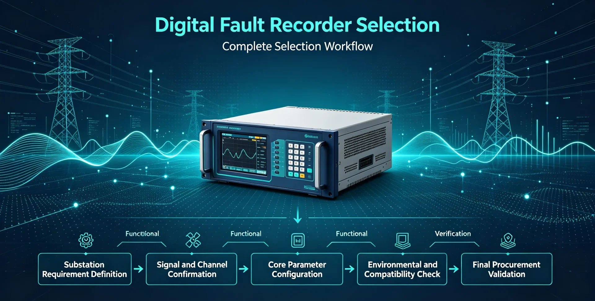
This article walks you through the complete Digital Fault Recorder Selection workflow: substation requirement definition → signal and channel confirmation → core parameter configuration → functional verification → environmental and compatibility check → final procurement validation.
What Should You Consider When Selecting a Digital Fault Recorder?
DFR selection depends on 10 core technical and operational factors that directly determine on-site applicability and data validity. The following overview table serves as a preliminary selection checklist for substation engineers and procurement teams.
| Selection Factor | Why It Matters |
|---|---|
| Analog input channels | Defines the maximum number of voltage and current waveforms the DFR can capture simultaneously for power system disturbance analysis |
| Digital input channels | Monitors binary status signals including breaker operations, protection trips, and interlocking actions to reconstruct full fault event sequences |
| Sampling rate | Determines waveform resolution and the ability to capture high-speed transients, switching surges, and short-duration power disturbances |
| Recording duration | Controls pre-fault and post-fault data retention, supporting complete fault inception, development, and clearing process analysis |
| Trigger functions | Guarantees automatic, accurate recording activation for targeted disturbances without invalid or missing fault records |
| Time synchronization | Enables precise timestamp alignment between DFR data, protection relays, breakers, and other substation IEDs for accurate event sequencing |
| Storage capacity | Supports long-term retention of repeated fault events, continuous monitoring records, and batch data export for periodic asset audits |
| Communication compatibility | Ensures seamless data transmission and remote access with existing substation automation systems (SAS) |
| Environmental rating | Guarantees stable operation in substation harsh conditions including temperature fluctuation, electromagnetic interference, and vibration |
| Analysis software & data format | Determines post-fault analysis efficiency, data interoperability, and standardized fault report generation |
Step 1 — Define the Substation’s Digital Fault Recorder Requirements
All DFR parameter configurations must start with on-site substation conditions. Unmatched requirement definition leads to over-specification (cost waste) or under-specification (function failure).
What Signals Need to Be Recorded?
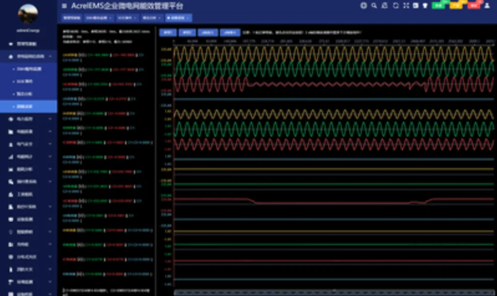
Substation DFRs capture two core signal categories, covering all data required for power system fault diagnosis.
Analog Signals (Waveform Recording)
- Three-phase phase current and residual current
- Three-phase phase voltage and zero-sequence voltage
- Transformer winding current/voltage and feeder electrical parameters
- Other customized AC analog measurement signals
Digital Signals (Status & Event Recording)
- Protection relay trip and reset signals
- Circuit breaker open/close status and operating state
- Substation alarm signals and interlocking action signals
- Switch device status and external trigger feedback signals
Key Rule: Confirm all signal types and quantities before selecting any DFR model, rather than adjusting functions after procurement.
How Many Circuits Need to Be Monitored?
Do not calculate channels based only on substation bay quantities. Use the standard engineering formula:
Total Required Channels = Number of Monitored Bays × Signals per Bay
Cover all core monitoring bays in the substation:
- Incoming and outgoing feeder bays
- Main and auxiliary transformer bays
- Bus coupler and bus section bays
- Generator connection bays (for power plant-linked substations)
Count analog and digital signals for each bay separately to obtain the final accurate channel demand.
Step 2 — Determine the Required Analog and Digital Input Channels
Channel quantity and type are the most fundamental DFR selection indicators, directly determining whether full substation signal coverage can be achieved.
Analog Input Requirements
Focus on matching substation secondary loop parameters to ensure signal adaptability and measurement accuracy:
- Number of three-phase current and voltage input channels (match bay monitoring scale)
- CT/VT secondary rated value compatibility (standard 1A/5A current, 100V voltage)
- AC effective measurement range and overload tolerance
- ADC sampling accuracy and linearity (determines waveform data credibility)
Digital Input Requirements
Avoid missing key event signals due to insufficient digital channels, a common on-site selection mistake:
- Breaker status and switching operation input channels
- Protection relay trip and logic action channels
- System alarm and interlocking signal channels
- External trigger reserved channels for extended monitoring
Step 3 — Choose the Appropriate Sampling Rate
The sampling rate defines the frequency of electrical waveform collection. A higher sampling rate is not universally better; the optimal value matches the substation’s fault analysis objectives.
Different application scenarios correspond to standardized sampling rate configurations:
- Standard power-frequency disturbance recording: 1–4 kHz, suitable for overcurrent, overvoltage, and frequency anomaly analysis
- Conventional protection operation analysis: 8–16 kHz, meets general relay action and fault clearing process verification
- Short-duration disturbance capture: 16–32 kHz, applicable to voltage sags, swells, and transient disturbances
- High-speed transient and surge analysis: 32 kHz and above, for switching transient, lightning surge, and high-frequency oscillation fault diagnosis
Core Principle: Select the lowest qualified sampling rate for actual demands to reduce unnecessary storage occupation and data processing pressure.
Step 4 — Determine Pre-Fault and Post-Fault Recording Time
A complete fault analysis requires full-cycle data from system steady state before the fault to system stabilization after fault clearing. The recording window is defined as: Pre-fault time + fault duration + post-fault time.
Why Is Pre-Fault Recording Important?
Pre-fault data records the substation’s steady operating state before disturbance occurrence, helping engineers identify fault root causes: baseline load current, normal voltage level, system operating mode, and accurate fault inception time point.
Why Is Post-Fault Recording Important?
Post-fault data tracks the full process of protection actuation, breaker tripping, fault isolation, voltage recovery, and system re-stabilization. It verifies whether protection and switching devices operate correctly and analyzes fault spreading and clearing efficiency.
Practical Configuration Reference: General distribution substations adopt 200ms–500ms pre-fault recording and 1s–3s post-fault recording; transmission substations adopt 500ms–1s pre-fault and 3s–5s post-fault recording.
Step 5 — Evaluate DFR Trigger Functions
Trigger functions determine when the DFR activates recording. Flexible, multi-dimensional trigger logic ensures no valid fault records are missed and avoids massive invalid data accumulation.
Common Trigger Conditions
- Analog threshold triggers: overcurrent, under/overvoltage, frequency deviation, rate of frequency change
- Digital signal triggers: protection trip signal, breaker switch action, alarm signal mutation
- Extended triggers: external hardware trigger, user-programmable custom logic trigger
Selection Standard: The DFR must support combined trigger logic to capture all conventional and customized disturbances in the substation, with adjustable trigger threshold sensitivity.
Step 6 — Check Time Synchronization Requirements
Accurate time synchronization is the basis for multi-device joint fault analysis. Substation fault diagnosis requires correlating DFR waveforms, protection action logs, and breaker operation records by unified timestamps.
Why Does a DFR Need Accurate Time Synchronization?
Unsynchronized timestamps cause disordered event sequences, making it impossible to distinguish fault cause and effect, verify protection coordination logic, and provide credible data for grid fault accountability and optimization.
What Time Synchronization Methods Should You Consider?
Select based on substation automation system architecture and existing device configuration:
- GPS synchronization: Wide applicability, suitable for most outdoor substation scenarios
- IRIG-B: Wired high-precision time synchronization, stable for indoor cabinet deployment
- PTP (IEEE 1588): High-precision network synchronization, matching modern IEC 61850 process bus architecture
- NTP: Basic network time synchronization, applicable to low-precision monitoring scenarios
Step 7 — Evaluate DFR Storage Capacity
DFR storage demand is determined by four core factors: total channel quantity, sampling rate, single recording window duration, and expected annual fault event volume.
Storage Demand Logic: More channels + higher sampling rate + longer recording time = larger storage space required
Storage selection cannot only pursue large capacity; focus on practical operational performance:
- Support automatic cyclic coverage of historical records
- Fast record retrieval and classified query by time/event type
- Local offline storage + remote backup dual mechanism
- Support batch data export without interrupting real-time recording
Step 8 — Check Communication and Data Export
DFR communication compatibility determines whether fault data can be integrated into the substation’s existing monitoring system, realizing remote viewing, analysis, and centralized management.
Communication Interfaces
Priority matching with on-site wiring conditions: Ethernet port, serial communication port, and fiber optic communication interface (anti-interference for high-voltage substation environments).
Substation Communication Protocols
Match substation automation system mainstream protocols to ensure seamless interoperability:
- IEC 61850: Standard for modern smart substations, supporting full data interoperability
- Modbus: Universal industrial protocol for basic data transmission
- DNP3: Applicable for utility grid remote monitoring and data interaction
Step 9 — Consider DFR Data Analysis Software
Hardware parameters determine recording capability, while software functions determine data utilization value. A DFR is only useful if engineers can efficiently retrieve, analyze, and apply fault data.
Core software functions for selection reference:
- Multi-channel waveform synchronous display and comparison
- Automatic event timeline sorting and fault point positioning
- Digital status signal and waveform linkage analysis
- Standard data format export and automatic fault report generation
- Remote parameter configuration and real-time data monitoring
Step 10 — Check Environmental and Installation Requirements
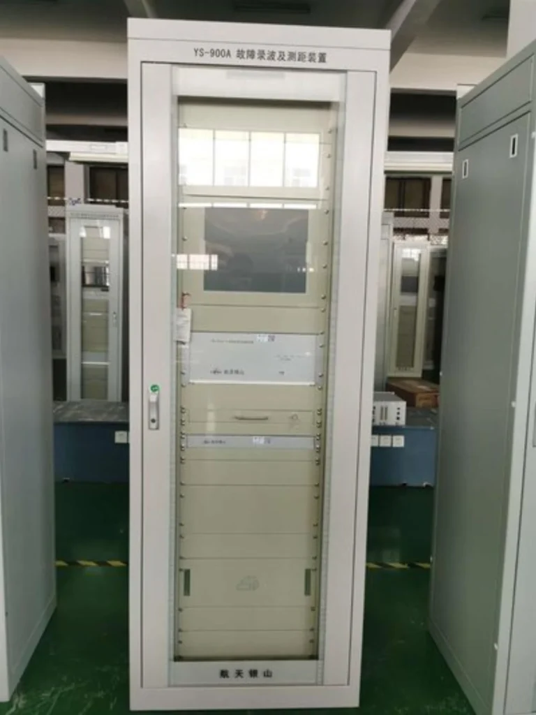
Substations have strong electromagnetic interference, temperature/humidity fluctuation, and mechanical vibration. Environmental and installation adaptability determines long-term DFR operational stability.In practical substation projects, digital fault recorders are mostly deployed as complete fault‑recorder panel assemblies.
Installation Requirements
- Support standard rack mounting or panel mounting, matching substation cabinet size
- Adapt to substation auxiliary power supply specifications
- Reserve reasonable wiring space and heat dissipation conditions
Environmental Conditions
- Wide operating temperature and humidity adaptation range
- High EMC electromagnetic interference resistance (meets substation industrial standards)
- Vibration and impact resistance for long-term stable operation
DFR Technical Specifications Checklist (Procurement Version)
Use this standardized checklist for final technical verification before DFR procurement to avoid parameter omission.
| Specification Item | Key Verification Content |
|---|---|
| Analog inputs | Total quantity, CT/VT secondary matching, measurement accuracy |
| Digital inputs | Quantity of status/trip/alarm channels, signal voltage adaptation |
| Sampling rate | Match disturbance analysis requirements, no excessive or insufficient configuration |
| Waveform resolution | ADC bit depth, steady-state and transient waveform fidelity |
| Recording mode | Continuous monitoring + trigger automatic recording dual mode |
| Pre/post-fault recording | Configurable duration, meet full-cycle fault analysis |
| Trigger functions | Analog/digital/programmable multi-type combined trigger |
| Time synchronization | Support GPS/IRIG-B/PTP/NTP, high timestamp accuracy |
| Storage | Effective capacity, cyclic coverage, event retention cycle |
| Communication | Interface type, support IEC 61850/Modbus/DNP3 protocols |
| Software function | Waveform analysis, report generation, remote configuration |
| Environmental adaptability | Temperature/humidity range, EMC level, vibration resistance |
| Installation & power | Mounting method, auxiliary power matching, wiring adaptability |
How to Select a DFR Based on Substation Size and Application
DFR configuration must match substation monitoring complexity. The following classification is based on actual monitoring demands rather than simple voltage level division.
Small Distribution Substation
Applicable scenarios: End distribution substations with few feeders and simple protection logic.
Core Configuration Requirements: Limited analog/digital channels, basic power-frequency waveform recording, breaker and protection trip signal monitoring, and conventional communication protocols. No high-precision transient analysis or multi-device time synchronization demands.
Medium Substation
Applicable scenarios: Regional power supply substations with multiple feeders and transformer protection monitoring.
Core Configuration Requirements: Sufficient analog channels for multi-bay monitoring, complete digital signal acquisition, standard time synchronization function, independent event storage space, and support for basic fault waveform analysis and data export.
Large Transmission Substation
Applicable scenarios: Grid hub substations undertaking power transmission and grid connection tasks, with complex operating conditions and high fault analysis requirements.
Core Configuration Requirements: High channel count for full multi-bay coverage, comprehensive digital signal monitoring, high sampling rate for transient capture, high-precision PTP/GPS time synchronization, large-capacity event storage, full IEC 61850 system integration, and professional advanced fault analysis functions.
DFR Selection Example: A Typical Substation
Project Requirement: A regional medium substation needs to monitor 4 transmission lines, 2 main transformers, and 1 bus coupler bay. Each bay requires three-phase current/voltage waveform recording and breaker/protection binary signal monitoring.
Step-by-Step Selection
- Analog channel calculation: 7 monitoring bays × 6 analog signals (3 current + 3 voltage) = 42 analog channels
- Digital channel calculation: 7 bays × 2 core digital signals (breaker status + trip signal) = 14 digital reserved channels
- Sampling rate confirmation: Adopt 16 kHz, meeting conventional fault and short-duration transient analysis demands
- Recording window configuration: 500ms pre-fault recording + 3s post-fault recording
- Trigger setting: Combine overcurrent/overvoltage analog trigger and protection trip digital trigger
- Time synchronization: Adopt IRIG-B + GPS dual synchronization to match substation smart system
- Communication protocol: Support IEC 61850 for seamless connection with substation automation system
Final Conclusion: DFR selection must integrate full signal demand, operating scenarios, and analysis requirements. Single-parameter optimization cannot meet substation long-term operational needs.
Common Mistakes When Selecting a Digital Fault Recorder
Choosing a DFR Only by Sampling Rate
A high sampling rate cannot compensate for insufficient channels, missing signal types, or inflexible trigger logic. Excessively high sampling rates only waste storage and computing resources without improving fault analysis accuracy.
Underestimating Digital Inputs
Most teams focus only on CT/VT analog signals and ignore protection trip, breaker status, and interlocking signals. Insufficient digital channels lead to incomplete fault event sequence reconstruction.
Ignoring Pre-Fault Recording
Lack of pre-fault data makes it impossible to judge system baseline conditions before faults, resulting in inability to accurately identify fault inducements and hidden grid risks.
Ignoring Time Synchronization
Unsynchronized timestamps cause disordered multi-device event logs, making joint fault analysis and protection logic verification invalid.
Focusing Only on Hardware
Overemphasizing hardware parameters while ignoring analysis software, data export compatibility, after-sales technical support, and equipment maintainability leads to low actual utilization of high-performance hardware.
DFR Selection Checklist for Substation Engineers
Complete all items below to finish standardized DFR procurement verification:
- ☐ Confirm and count all monitored substation bays
- ☐ Calculate total required analog input channels
- ☐ Calculate total required digital input channels
- ☐ Match sampling rate with fault analysis scenarios
- ☐ Confirm qualified pre-fault and post-fault recording duration
- ☐ Configure complete trigger condition logic
- ☐ Verify time synchronization method and accuracy
- ☐ Calculate storage capacity and event retention cycle
- ☐ Check compatibility of communication interfaces and protocols
- ☐ Verify waveform analysis software and data export functions
- ☐ Confirm power supply and environmental adaptation parameters
- ☐ Verify on-site installation and wiring conditions
- ☐ Review manufacturer’s testing certification and technical support capabilities
FAQs About Digital Fault Recorder Selection
What is the most important specification when selecting a DFR?
No single parameter determines DFR performance. Channel matching, sampling rate, recording duration, trigger flexibility, time synchronization accuracy, and system compatibility must be comprehensively evaluated according to substation actual demands.
How many channels does a substation DFR need?
Channel quantity depends on the number of monitored bays and signals per bay. Distribution substations usually require 20–60 channels, while large transmission substations require 60–120+ channels for full coverage.
What sampling rate should a DFR have?
1–4 kHz for basic power frequency fault recording; 8–16 kHz for conventional protection analysis; 32 kHz and above for high-speed transient and surge disturbance analysis.
How much pre-fault recording time is required?
200–500ms for general distribution substations; 500ms–1s for transmission substations to capture complete fault inception and system pre-fault state.
What digital inputs should a DFR record?
Core digital signals include protection trip/reset signals, breaker open/close status, system alarm signals, and interlocking action signals.
Does a DFR need GPS time synchronization?
Large and medium substations require GPS or PTP high-precision synchronization for multi-device event alignment; small distribution substations can adopt NTP or IRIG-B synchronization according to demands.
What communication protocols should a substation DFR support?
Modern smart substations prioritize IEC 61850; traditional grid systems adapt to Modbus and DNP3 protocols to ensure seamless system integration.
What is the difference between DFR specifications and protection relay specifications?
Protection relays focus on real-time fault judgment and action output, while DFRs focus on full-process data recording and post-fault analysis. DFR parameters prioritize waveform fidelity and data integrity, different from protection relay action threshold accuracy.
Can one DFR monitor multiple substation bays?
Yes. A single high-channel DFR can centrally monitor multiple bays, provided that the total channel quantity, sampling performance, and storage capacity meet the total monitoring load.
Conclusion
The right digital fault recorder for a substation is not the model with the highest sampling rate, largest storage, or most channels. It is the solution whose signal acquisition capability, recording configuration, trigger logic, synchronization accuracy, communication compatibility, and analysis functions fully match the substation’s scale, operating characteristics, and fault analysis requirements.
Scientific DFR selection improves substation fault diagnosis efficiency, reduces grid operation risks, and provides reliable data support for power system optimization and asset management.
Technical Support & Custom Solution: Need professional engineers to match DFR specifications for your substation project? Submit your substation single-line diagram, signal list, or technical requirements, and our technical team will provide customized DFR selection and configuration solutions for EPC and utility projects.
Reference & Technical Sources
- IEC 61850: Communication Networks and Systems for Power Utility Automation
- IEEE C57.12.200-2022: Guide for Dielectric Frequency Response Measurement of Power Apparatus Bushings
- NERC PRC-028: Disturbance Monitoring and Reporting Requirements
- IEEE 1588 (PTP): Precision Clock Synchronization Protocol for Networked Measurement and Control Systems
- IET Digital Library: Application of IEC 61850 Process Bus in DFR Deployment (2018)



About Author

Hello, I'm Leno Zhang. I have 15 years of experience in the power relay protection industry with extensive pre-sales and after-sales project experience. Our company specializes in various complete sets of relay protection and automation equipment. I can assist customers in solving all practical on-site project challenges and provide optimal integrated solutions.
Tell Us Your Requirement
High Quality
Stable performance, reliable design, ensuring safe operation for power system protection and grid stability.
Fast Delivery
Timely delivery to support your urgent orders and project schedules efficiently and professionally at any time.
Best Warranty
Professional Warranty: Reliable after-sales support for stable relay protection and long-term customer satisfaction.