
-
Leon Zhang Sales Manager
-
Email: sale@relayprotect.com
-
Phone/WhatsApp: +86 13655813266
Transformer Differential Protection Testing: Methods, Procedures
Transformer differential protection testing confirms two things: the 87T relay trips for internal faults, and it stays stable through inrush and through-faults. Factory defaults prove neither. Commissioning before energization, and re-testing at every maintenance interval, is what closes the gap.
Written by Leon Zhang, Protection Application Engineer · Technical review by the relayprotect.com engineering team · Last reviewed September 2026
Related: transformer differential protection working principle, 87T setting, and protection relay testing and commissioning.
For EPC contractors and owner engineers, the test records decide acceptance. A full sequence spans CT circuits, relay logic and trip wiring, and it ends with a signed report the power plant owner can file.
What 87T Testing Verifies on Site
Purpose of 87T Protection Testing
Transformer differential protection testing covers the full chain, not one relay operation. CT sampling, relay logic, trip circuit and breaker operation all have to line up.
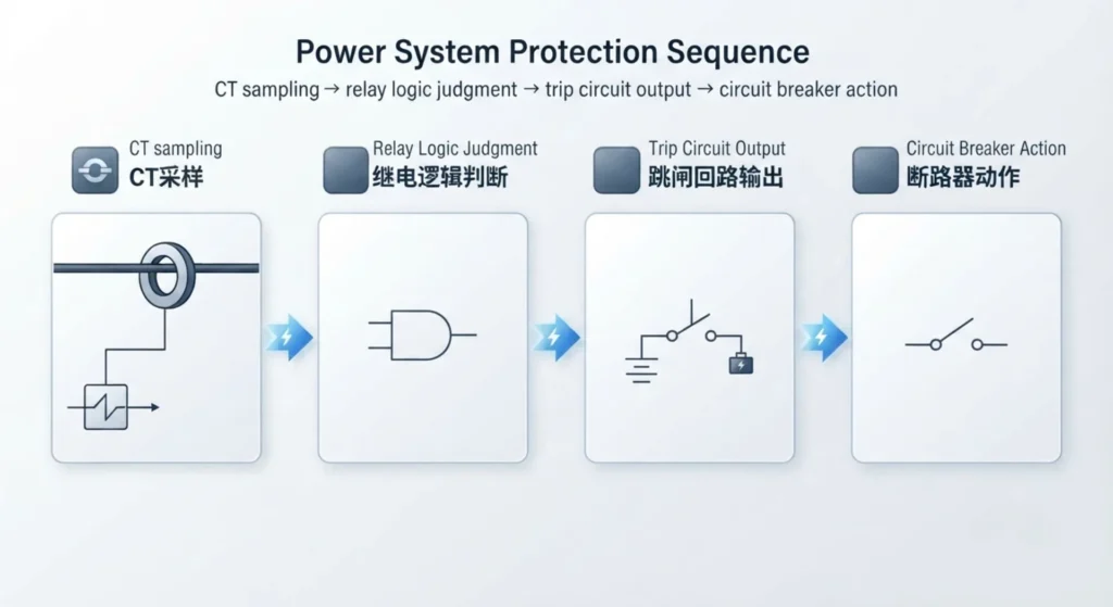
Five items carry the load on site:
- Verify the operating characteristics, sensitivity and action accuracy of differential protection relays
- Check CT ratio matching, polarity correctness and phase sequence compensation effect
- Calibrate key protection settings including differential pickup current, bias slope and harmonic restraint threshold
- Confirm the validity of fault trip logic, alarm output and interlocking functions
- Eliminate hidden dangers such as false tripping and refusal action to meet grid commissioning acceptance standards
Selecting a relay for a live project?
Send the system voltage, CT ratio and tripping scheme. Our engineers confirm the model and reply within 12 hours.
Main Test Items on a Transformer Differential Relay
The routine tests split into static parameter checks and dynamic fault simulation:
1. Pickup Current Test
This test finds the minimum operating current and shows how much sensitivity the setting leaves. Too high a pickup misses winding faults low in the tank; too low a pickup invites trips on load.
2. Differential & Restraining Current Test
Core test for biased differential protection. It simulates through-current and internal fault current, then checks how operating current tracks restraining current. The relay has to act on internal faults and hold back on load current.
3. Slope Test (Bias Characteristic Test)
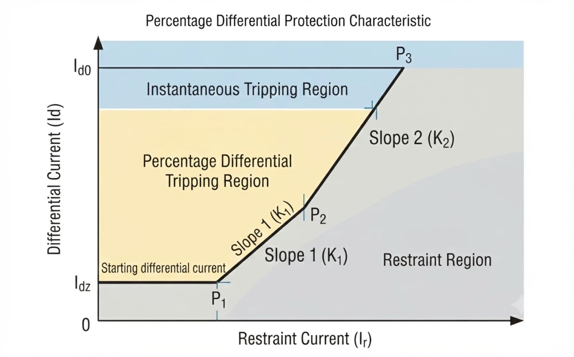
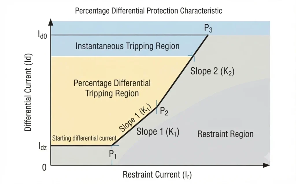
The slope test is the anti-maloperation check. Most digital differential relays use a single or dual-slope bias characteristic. This test calibrates the percentage bias slope setting, and it is what stops slight CT saturation during an external fault from turning into a false trip.
4. Harmonic Restraint Test
This test targets magnetizing inrush, the classic source of 87T false trips. On energization the second harmonic content of the inrush has to drive the relay into restraint before the differential element can pick up.
5. CT Polarity and Ratio Verification
CT polarity and CT ratio come first in transformer differential protection testing. Wrong polarity, a mismatched ratio or a wrong phase compensation setting all leave standing differential current, and the outcome is either constant nuisance tripping or a relay that never sees a real fault. CT wiring and parameter errors account for a large share of commissioning failures.
87T Test Methods: Primary and Secondary Injection
Three methods cover most overseas substation commissioning. Pick one by substation type, transformer rating and the commissioning window available.
Primary Injection Testing Method
Primary injection pushes rated or fault current through the transformer primary. That exercises the whole loop, CTs, relay, secondary wiring and breaker, under real operating conditions.
Core advantages: the test matches the real grid operating state, so the measured response covers CTs, wiring, relay and breaker together.
Limitations: needs high-capacity primary test equipment, heavy on-site wiring, and a long test window.
Applicable scenarios: hub substations, high-voltage main transformer projects, and any job that needs full system acceptance.
Secondary Injection Testing Method
Secondary injection is the workhorse of on-site commissioning. The test set reproduces CT secondary current, phase angle deviation and internal or external fault signals, and injects them straight into the relay secondary terminals.
Core advantages: no primary outage and no high-current source needed, simple wiring, and safe to run on any digital differential relay.
Applicable scenarios: everyday substation commissioning, routine maintenance, small and medium transformer protection, and batch acceptance.
IEC 61850 Transformer Differential Protection Testing
For intelligent digital substations that comply with IEC 61850 standards, traditional analog secondary injection is no longer applicable. This testing method focuses on digital signal verification, including GOOSE message trip logic, SV sampled value transmission accuracy, and network communication linkage performance.
Test focus: digital signal synchronization, message delay, fault identification accuracy, and trip logic under real network traffic.
Applicable scenarios: digital substation EPC projects and acceptance testing on intelligent transformer protection systems.
87T Commissioning: Step-by-Step Procedure
These transformer differential test procedures follow the sequence used on EPC substation projects: documents first, then injection, then the signed report. Skipping a step here shows up later as a nuisance trip.
Step 1 – Review Transformer and Protection Documents
Collect the documents before touching the relay. You need the transformer nameplate, the substation single-line diagram, CT ratios and vector group, the relay setting sheet and the coordination study.
Step 2 – Verify CT Connections and Polarity
Verify CT primary and secondary wiring, phase sequence, polarity and the vector group compensation settings against the drawing. Re-tighten every terminal: one loose connection is enough to fail the tests in Step 4.
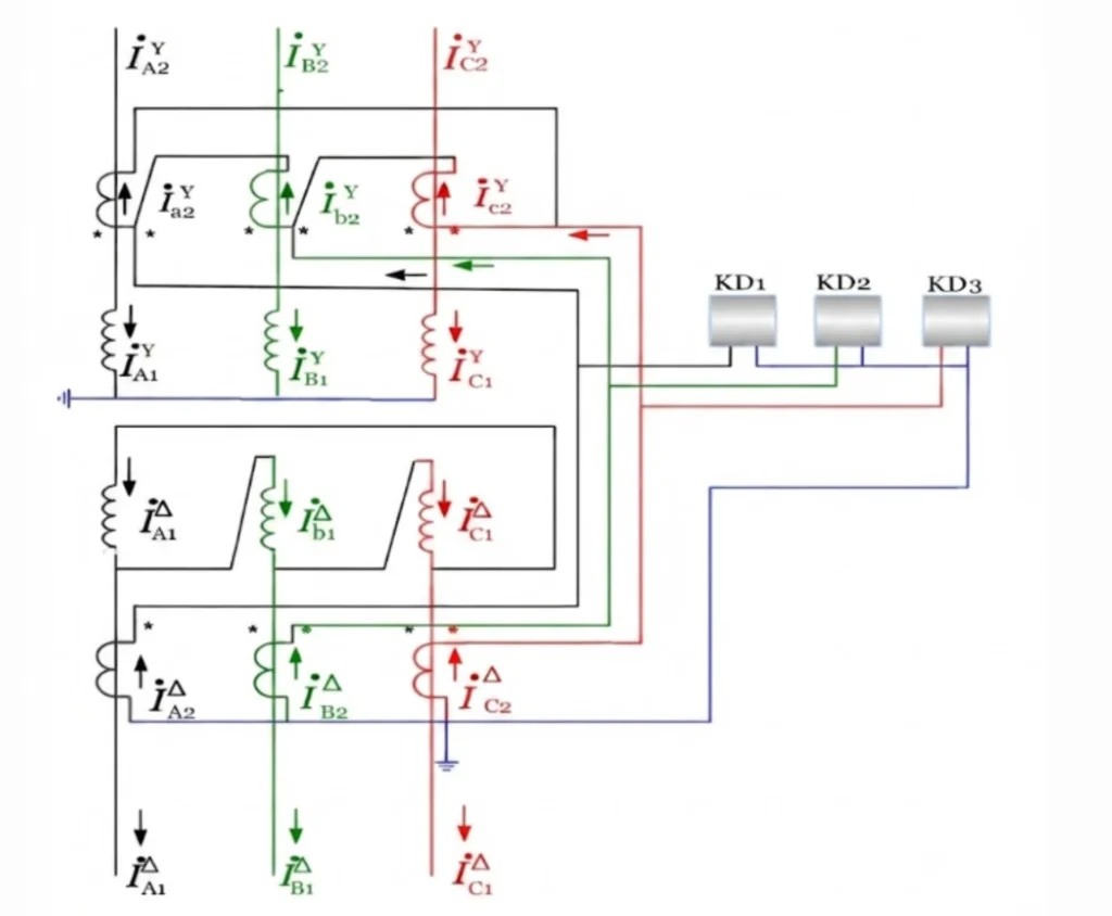
The CT secondary connection must be opposite to the transformer winding connection, so the phase displacement cancels out.
For example, CTs on the transformer Y-connected side should be connected in delta (Δ), while CTs on the transformer Δ-connected side should be connected in star (Y). In addition, all CT secondary circuits must have only one grounding point, which is normally located at the protection panel.
Phase Compensation Connection
For common transformer vector groups such as Yd11, the CT secondary connections must provide phase compensation:
- The CT secondary windings on the transformer star (Y) side are connected in delta (Δ).
- The CT secondary windings on the transformer delta (Δ) side are connected in star (Y).
This connection compensates the 30° phase shift introduced by the transformer winding connection, so differential current stays near zero in normal operation and the relay does not operate.
CT Polarity Requirements
All CTs must follow the subtractive polarity principle.
Key requirements:
- The polarity terminals (marked terminals) of all CTs should face the same direction, usually toward the busbar side (or another uniformly defined reference direction).
- CT polarity terminals should be connected together according to the differential protection scheme.
Correct polarity gives three results:
- Normal load current flows correctly through the differential circuit.
- External faults do not create false differential current.
- Differential relay maloperation is prevented.
CT Secondary Circuit Grounding Requirements
The CT secondary circuit must have one and only one grounding point.
Standard practice:
- The grounding point is normally installed at the protection panel terminal block.
- The delta-connected CT secondary circuit must not be grounded, otherwise it may create a short circuit.
- The neutral point of the star-connected CT secondary circuit can be grounded when required.
- Multiple grounding points must be avoided because they can create circulating currents, resulting in incorrect differential current and possible relay maloperation.
Step 3 – Load Standard Relay Settings
Load the calculated values: differential pickup, restraint current, Slope 1 and Slope 2, second harmonic restraint ratio and time delay. Then check each one against the grid connection study rather than the relay default.
Step 4 – Perform Relay Functional Tests
Simulate three conditions: an internal short circuit, an external through-fault and energization inrush. The relay must trip for the first, stay stable for the other two, and operate the trip and alarm contacts every time.
Step 5 – Generate Standard Test Report
Record every injected value, the measured value, the action time and the result. Mark each item pass or fail. On most projects the 87T commissioning record is the first document the owner asks for at handover.
| Record item | Set value | Measured value | Result |
|---|---|---|---|
| CT ratio and polarity | Per CT nameplate | Pass / Fail | |
| Differential pickup (A) | Pass / Fail | ||
| Slope 1 / Slope 2 (%) | Pass / Fail | ||
| 2nd harmonic restraint (%) | Pass / Fail | ||
| Trip time (ms) | Pass / Fail | ||
| Trip circuit continuity | Continuous | Pass / Fail |
Transformer Differential Protection Test Equipment
Test set capability decides what the commissioning window can absorb. A three-phase set with independent phase-angle control covers most 87T work; six-phase sets are needed once vector group compensation and dual-slope logic are in play.
Conventional Relay Protection Test Set
This is the workhorse for substation commissioning, with multi-channel current and voltage output, adjustable phase angle and standard fault simulation. Portable and low cost, it covers most LV and MV transformer differential relay work and suits projects testing many relays in one trip.
Six-Phase Relay Test System for Transformer Protection
Six-phase sets drive 3-phase current and 3-phase voltage synchronously. That is what vector group compensation, dual-slope logic and harmonic restraint testing demand. One pass covers the full item list on a high-voltage transformer differential protection scheme, so large EPC projects usually specify one.
Automated Transformer Differential Protection Testing Software
Software builds the sequence from templates, acquires the data and writes the English report. Check the template version against the relay firmware before trusting the output.
Common Transformer Differential Protection Testing Problems
Most commissioning failures come back to six symptoms. Each one points at a different part of the chain.
| Symptom | Likely cause | Check to run |
|---|---|---|
| Differential current under normal load | CT polarity, ratio or vector group configuration | Check CT wiring and relay settings |
| False trip during external fault simulation | Incorrect slope or CT saturation | Perform slope and stability test |
| Trip during energization | Harmonic restraint configuration | Perform harmonic restraint test |
| Relay does not trip | Pickup too high or test current too low | Perform pickup test |
| Unequal HV/LV currents | CT ratio or compensation error | Verify CT ratio and vector group |
| Trip output does not reach breaker | Trip circuit problem | Perform trip circuit test |
Check CT polarity first. It explains most of the rows above.
IEC Standards Applied to 87T Testing
These procedures, and the equipment performance figures below, follow IEC standards, which is what owner and third-party inspectors check against:
- IEC 60255-1:2022: measuring relays and protection equipment, common requirements. It sets the test methods, reference conditions and accuracy rules a relay type test follows
- IEC 61869-2:2012: additional requirements for current transformers, covering ratio, polarity and accuracy for differential protection
- IEC 61850-10:2012: conformance testing for substation automation, including GOOSE and SV signal verification on digital transformer protection
Transformer Differential Protection Testing – Q&A
Q1. What is transformer differential protection testing?
It is the process of proving the 87T relay behaves as calculated. Commissioning closes the gap between a setting sheet and a relay, and it covers secondary injection, primary injection and functional checks on CT wiring, polarity, pickup, slope, harmonic restraint and trip logic. The target is simple: trip for internal faults, stay stable for everything else.
Q2. How do you test an 87T transformer differential relay?
Testing an 87T relay needs both injection methods. Secondary injection applies simulated currents straight to the relay terminals and verifies pickup, slope, harmonic restraint and trip timing. Primary injection pushes current through the actual CT circuit and validates polarity, wiring and the whole protection path.
Q3. What tests are performed on transformer differential protection?
The standard set of checks, and what each one proves:
| Test item | What it proves |
|---|---|
| CT polarity and wiring check | HV and LV currents are in the correct phase relationship |
| Pickup test | The relay operates at the set threshold |
| Bias / slope test | The percentage restraint characteristic is right |
| Harmonic restraint test | Inrush blocking works |
| Trip logic test | Output contacts and alarms behave as designed |
| Primary injection test | The complete path from CTs to relay is sound |
Q4. What equipment is used for transformer differential relay testing?
A three-phase secondary injection set is the main tool, with independent current per phase and adjustable magnitude and phase angle. Add a phase angle meter, a multimeter, a primary injection set for through-fault tests, and the relay manufacturer’s test software. Some modern sets inject harmonics as well, which is what the restraint test needs.
Q5. How do you perform a transformer differential relay secondary injection test?
Run the sequence in this order:
- Isolate the relay from the CT circuits and connect the test set to the relay’s analog inputs
- Calculate the expected operate currents based on the relay settings
- For pickup test: inject balanced currents and gradually increase one side until the relay operates
- For slope test: inject currents at multiple points along the restraint characteristic
- For harmonic test: inject fundamental current with superimposed harmonics
- Record operate times and compare against expected values
- Verify trip contacts operate correctly
Log every result against the relay serial number. That log is what separates a relay fault from a wiring fault six months later.
Q6. What is the difference between primary and secondary injection testing?
The difference between primary and secondary injection testing lies in what is being verified:
| Aspect | Secondary Injection | Primary Injection |
|---|---|---|
| Test point | Relay analog inputs | Complete protection loop |
| Current source | Test set directly | Primary current injected through CTs |
| Verifies | Relay internal settings and logic | CT circuits, polarity, wiring, relay |
| When used | Commissioning, periodic maintenance | Commissioning, major modifications |
| System status | Transformer de-energized | Transformer energized |
Secondary injection tests the relay alone; primary injection tests the entire protection system.
Q7. How do you test the differential protection slope?
The slope test needs two currents and a plot:
- Calculate the expected operate points based on the relay’s slope settings (Slope 1 and Slope 2)
- Using a secondary injection test set, inject two currents representing the HV and LV sides
- For each test point, set the restraint current at a known value and gradually increase the differential current until the relay operates
- Record the operate points and plot them against the relay’s characteristic curve
- Confirm that the measured slope matches the set values
- Test multiple points across both slope regions to verify the entire characteristic
The plot is the deliverable. If the measured points sit off the published characteristic, the slope settings and the relay firmware disagree.
Q8. How do you test harmonic restraint in transformer differential protection?
Two signals go in together, a fundamental and a second harmonic:
- Using a test set capable of harmonic injection, inject a fundamental current with a superimposed second harmonic component
- Set the fundamental current above the differential pickup threshold
- Gradually increase the harmonic content until the relay restrains (does not operate)
- Record the harmonic percentage at which restraint occurs and compare with the set value
- For cross-blocking relays, verify that inrush detection on one phase restrains operation on other phases if applicable
This confirms the relay correctly blocks tripping during simulated inrush conditions while remaining sensitive to internal faults.
Q9. Why is CT polarity important during transformer differential protection testing?
Incorrect polarity puts the HV and LV currents out of phase, which leaves a standing differential current under normal load. During testing, polarity has to be verified so the two CT sets sum or subtract the way the relay’s compensation method expects. Get it wrong and the relay either trips on load or never sees the real fault.
Q10. How often should transformer differential protection be tested?
Interval depends on site practice and the local grid code. In most plants it works out as:
- Commissioning – full testing of all functions and primary injection
- Annual or biennial maintenance – secondary injection tests and functional checks
- After modifications – any CT changes, relay setting changes, or primary equipment modifications require retesting
- After fault events – testing is recommended to confirm relay and CT performance remains intact
Where the relay manual or the site maintenance schedule is stricter than the grid code, follow that.
What a 5 A CT does to a 1 A differential relay
Before energising, two numbers are worth reading off the nameplate: the CT secondary rating and the relay input rating. On one project they were 5 A and 1 A. The consequences show up in three places. Every value in the setting sheet is five times off in primary terms. At rated load the current input already carries about 4.4 x In on a 200/5 CT, sitting at its continuous limit. And the linear measuring range shrinks by a factor of five – a 1 A relay on a 200/5 CT runs out of linear range at roughly 1,600 A primary, so an ordinary 8 x rated through-fault drives the input to about 35 x In. Secondary injection at one fifth of the expected pickup finds it immediately. All installations are listed in the project record.
References
| Source | What it covers | Type | Edition |
|---|---|---|---|
| IEC 60255-1 | Measuring relays and protection equipment – common requirements and test methods | Standard | 2022 |
| IEC 61869-2 | Instrument transformers – current transformers: ratio, polarity, accuracy | Standard | 2012 |
| IEC 61850-10 | Substation automation – conformance testing (GOOSE and SV signals) | Standard | 2012, amd 2025 |
| IEEE C37.91 | Guide for protective relay applications to power transformers | Standard | Confirm current edition |
| IEEE C57.12.90 | Test code for liquid-immersed distribution, power and regulating transformers | Standard | Confirm current edition |
| Relay manufacturer manuals | Test templates, pickup / slope / harmonic restraint test values | Manufacturer document | Per relay model |
If the selection has to be checked against your switchboard, send the single-line and the ratings.
About Author

Hello, I'm Leon Zhang. I have 15 years of experience in the power relay protection industry with extensive pre-sales and after-sales project experience. Our company specializes in various complete sets of relay protection and automation equipment. I can assist customers in solving all practical on-site project challenges and provide optimal integrated solutions.
Tell Us Your Requirement



High Quality
Stable performance, reliable design, ensuring safe operation for power system protection and grid stability.
Fast Delivery
Timely delivery to support your urgent orders and project schedules efficiently and professionally at any time.
Best Warranty
Professional Warranty: Reliable after-sales support for stable relay protection and long-term customer satisfaction.