

-
Leon Zhang sales consultant
-
Email: zxl635973785@gmail.com
-
Phone/WhatsApp: +86 13655813266
Protection Relay Setting Calculation
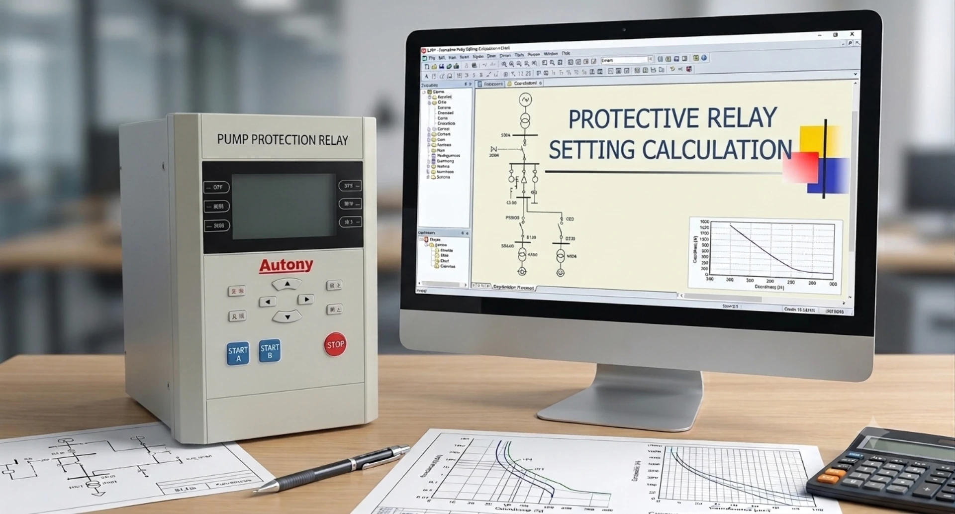
Today let’s talk about Protection Relay Setting Calculation. When people first get in touch with it, they often fall into a misunderstanding: regarding Protection Relay Setting Calculation as simple mathematical operations.
Below are three common mistakes:
- Only focusing on numerical calculation while ignoring the practical meaning of protection coordination.
- Improper time grading margin, resulting in override tripping or protection failure to operate.
- Excessively pursuing sensitivity at the cost of protection reliability.
In fact, figuring out when the protection relay settings trigger tripping, when they should not, and which set of protection relay settings takes priority is the true essence covered in the protection relay setting guide.
What is relay protection setting calculation?
Simply put, Protection Relay Setting Calculation means configuring a complete set of operation rules for protection relays:
• What current threshold will trigger operation? (Operating current)
• How long is the time delay after fault detection before tripping? (Operating time)
• Which fault zones should this protection clear? (Protection coverage)
Three core setting principles of Protection Relay Setting Calculation
Relay protection follows three fundamental principles: selectivity, rapidity and reliability.
| Principle | Explanation |
|---|---|
| Selectivity | Only the protection nearest the fault operates when faults happen. |
| Rapidity | Fast fault clearance reduces equipment damage and maintains system stability; relays must respond within seconds. |
| Reliability | The fundamental requirement of relay protection, its core lifeline. |
Conflicts often exist among the three core principles when configuring a digital multifunction protection relay.
Enhancing rapidity may compromise selectivity, while pursuing higher sensitivity may reduce reliability. The core objective of Protection Relay Setting Calculation is to strike an optimal balance among the three.
Four Most Widely Used Protection Setting Methods in Practice
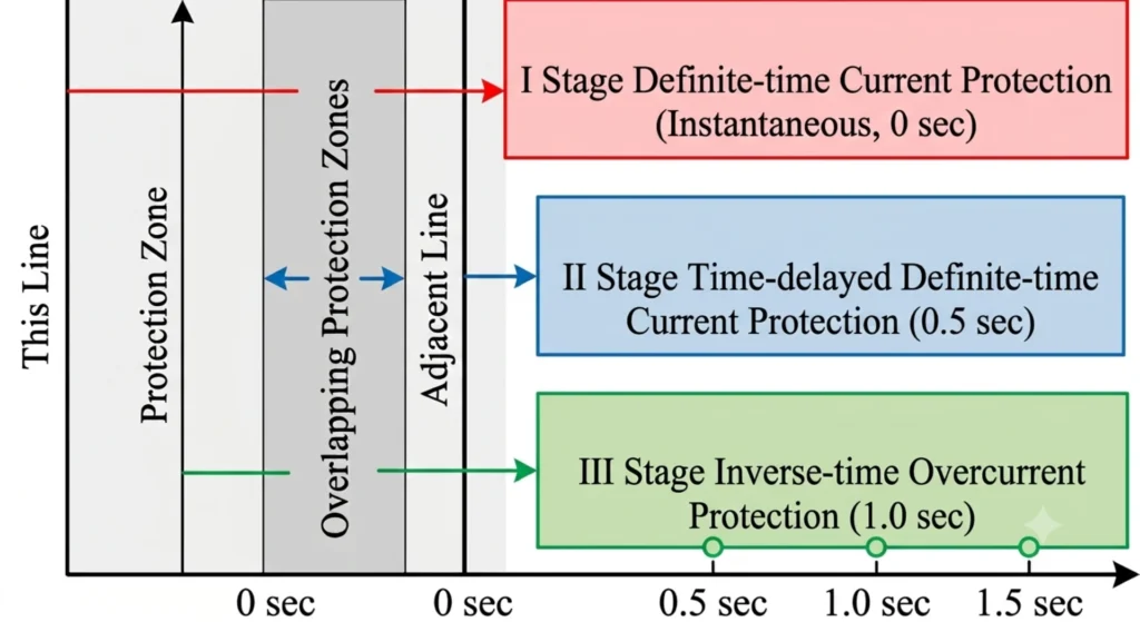
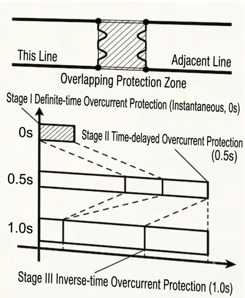
Three-stage overcurrent protection plus overload protection are commonly adopted in 10kV distribution systems.
Stage I: Instantaneous Overcurrent Protection
Features: Instantaneous operation (0s), covering only around 80% of the protected line.
Setting Rule: Avoid the maximum short-circuit current at the outlet of the adjacent downstream line, multiplied by a safety factor (normally 1.2~1.3).
Application: Main protection to instantly clear severe faults near the head of the protected line.
Stage II: Time-delayed Instantaneous Overcurrent Protection
Features: Operates with a short time delay (typically 0.5s), covering the entire length of the protected line.
Setting Rule: Coordinate with Stage I protection of the adjacent line; its operating current shall be higher than that of the adjacent Stage I, with an extra time grading margin.
Application: Backup protection for Stage I and main protection for the full line length.
Stage III: Overcurrent Protection
Features: Operates with a long delay (above 1s), covering the full length of the protected line and all adjacent downstream lines.
Setting Rule: Avoid the maximum load current, with consideration given to return coefficient and motor self-starting coefficient.
Application: Local backup for the protected line and remote backup for adjacent lines.
Overload Protection
Features: Long time delay (5~10s), alarm only without tripping the circuit breaker.
Setting Rule: Operating current slightly higher than rated load current (safety factor = 1.05).
Application: Monitor line load and prevent equipment burnout caused by overload.
Time Grading Margin Δt
- Inherent operating time of protection relay: roughly 50~100ms
- Inherent opening time of circuit breaker: roughly 40~80ms
- Safety margin time: roughly 200~300ms
The total of these times requires a minimum grading margin of 0.3~0.5s. If the margin is merely 0.1s, the upstream breaker will trip before the downstream breaker completes opening, resulting in override tripping faults.
Time grading margin acts as the “safety gap” for relay protection coordination, hence 0.5 seconds serves as the standard safety gap in power systems.
Higher sensitivity does not equal better setting calculation
A higher sensitivity factor does not mean superior relay protection performance.
Relay protection requires perfect coordination between all protection stages, complying with two rules:
- It must operate sensitively when faults occur within its protection zone;
- It must never malfunction during normal operation or external faults outside its jurisdiction.
Insufficient sensitivity leads to protection failure to operate under faults, triggering safety incidents.
Excessively high sensitivity causes false tripping under normal load fluctuations, which also results in accidents.
Therefore, the goal of setting calculation is not extreme sensitivity, but precise and reliable operation.
What hazards will be caused by incorrect protection relay settings?
Wrong settings of protection relays mainly bring four categories of severe hazards:
1. Failure of protection operation, expanding fault scope
Improper Protection Relay Setting Calculation may lead to low sensitivity and excessively high operating current settings. Under such circumstances, the relay fails to trip during line or equipment short-circuit and overload faults.
Persistent fault current will burn cables, transformers and motors, damage primary equipment, and even trigger bus faults and full substation blackouts.
2. Maloperation of protection, triggering large-scale power outages
Incorrect Protection Relay Setting Calculation may result in overly high sensitivity or inadequate time coordination margin, which triggers unwanted tripping during normal load fluctuations, motor restarting or distant external faults.
Fault-free feeders will be cut off simultaneously, causing widespread outages for factories and distribution grids, production halts and economic losses.
3. Override tripping, breaking selective coordination of protection
Improper Protection Relay Setting Calculation leads to unreasonable time grading margin Δt between upstream and downstream protections.
Upstream source-side relays trip before downstream faults are cleared, cutting off the entire feeder and substation outgoing circuits, expanding outage scope and complicating fault inspection and maintenance.
4. Damage to primary equipment, risks to personal safety and power system stability
Faults left uncleared due to flawed Protection Relay Setting Calculation produce huge short-circuit currents and overvoltages that break down insulation on transformers, switchgears and instrument transformers.
Prolonged grid fault stress can trigger system oscillation and voltage collapse. Mal-tripping interrupts power supply to critical loads and may cause safety accidents in high-risk industries including chemical and metallurgical plants. Uncontrolled faults also bring electric shock risks to maintenance personnel.
Conclusion
Relay protection functions as both the first and last line of defense for power systems. Every setting value is closely linked to the safe and stable operation of the power grid.
We deliver professional protective relay consulting services, including pre-project scheme optimization, to resolve all practical technical challenges encountered in customers’ power projects.
FAQ
How do protective relays work?
Protective relays monitor electrical parameters and send trip signals to circuit breakers rapidly once power system faults are detected.
How to reset the protective relay?
It can be reset manually on the panel or remotely via the control system after faults are cleared.
How to protect relay contacts?
Install surge absorption components such as varistors and freewheeling diodes to suppress arc and avoid contact ablation.
How does a lockout relay protect?
In relay protection, lockout relays output blocking signals upon detecting voltage circuit failure, system oscillation or external faults to block protection output circuits, avoiding false tripping and ensuring selectivity and reliability.
How to size up a current transformer for relay protection?
Select primary current according to load and short-circuit current, choose 1A/5A secondary current, confirm accuracy class, burden and knee-point voltage to prevent CT saturation.
How to coordinate instantaneous settings on protection relays?
Set instantaneous overcurrent pickup above the maximum through-fault current of adjacent downstream equipment to avoid unnecessary tripping. Match instantaneous delay and current thresholds to form clear time-current coordination between upstream and downstream relays.



About Author

Hello, I'm Leno Zhang. I have 15 years of experience in the power relay protection industry with extensive pre-sales and after-sales project experience. Our company specializes in various complete sets of relay protection and automation equipment. I can assist customers in solving all practical on-site project challenges and provide optimal integrated solutions.
Tell Us Your Requirement
High Quality
Stable performance, reliable design, ensuring safe operation for power system protection and grid stability.
Fast Delivery
Timely delivery to support your urgent orders and project schedules efficiently and professionally at any time.
Best Warranty
Professional Warranty: Reliable after-sales support for stable relay protection and long-term customer satisfaction.