

-
Leon Zhang sales consultant
-
Email: zxl635973785@gmail.com
-
Phone/WhatsApp: +86 13655813266
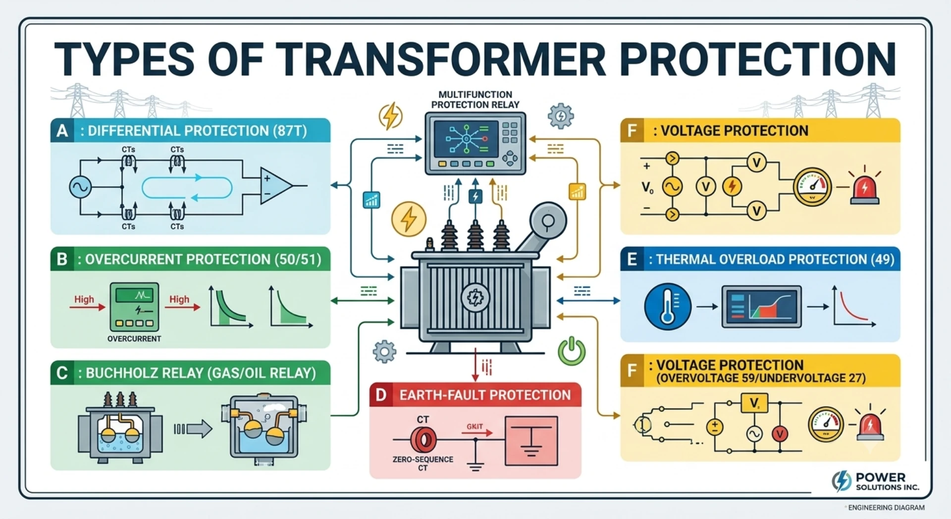
Types of Transformer Protection: Electrical and Mechanical Methods
Types of transformer protection split into electrical relays and mechanical devices, each aimed at a different fault mode. Written by Leon Zhang, Protection Application Engineer · Technical review by Li Ming, Electrical Engineer · Last reviewed September 2026.
Transformer Faults and Abnormal Conditions: Which Types of Transformer Protection Apply?
Types of transformer protection fall into two families: electrical relays that compare currents and voltages inside the transformer, and mechanical devices that react to gas, oil and temperature. Winding faults, overload, overexcitation and incipient gas decide which device applies. Each type below carries its ANSI device number and its place in a typical scheme.
Internal Electrical Faults
Internal electrical faults occur within the transformer tank and pose a high risk of damage. These include:
- Winding phase-to-phase faults – Short circuits between phases within the windings, producing large fault currents
- Winding earth faults – Short circuits between a phase winding and the transformer tank or grounded core
- Inter-turn faults – Short circuits between turns of the same winding, often producing relatively low fault currents but causing localized overheating
- Bushing faults – Flashover or breakdown of transformer bushings
Internal faults are typically detected by transformer differential protection (87T) and gas/oil transformer protection devices.
External Faults
External faults occur outside the transformer but still affect its operation. These include:
- External phase faults – Phase-to-phase faults on connected feeders or downstream equipment
- External earth faults – Ground faults on the system outside the transformer zone
- Through-fault current – High fault current flowing through the transformer during external system faults
External faults do not cause differential current but produce high through-current that can stress the transformer and CTs, requiring coordinated backup protection in the overall transformer protection system.
Abnormal Operating Conditions
Abnormal operating conditions are not immediate faults but may develop into more serious issues if not addressed:
- Overload – Extended operation above rated capacity, causing excessive temperature rise and insulation aging
- Overexcitation – Excessive voltage/frequency ratio, leading to core saturation and increased magnetizing current
- Overheating – High operating temperatures from overloads, cooling failures or other causes
- Low oil level – Reduced oil level in the tank, exposing winding insulation and reducing cooling
- Gas accumulation – Gas production due to partial discharges or thermal decomposition of oil and paper insulation
Abnormal pressure – Pressure build-up within the tank due to internal faults or gas accumulation
Protection Coordination
Different transformer protection types are designed for distinct transformer faults, and multiple protection methods are normally coordinated to provide primary and backup protection. Internal faults typically require fast tripping, while abnormal conditions may initiate alarms or delayed tripping to allow corrective action. The transformer protection ANSI codes used here are standard, but the logic block behind each one is not. The mapping lives in the manufacturer’s setting software.
Electrical Transformer Protection Functions
Types of transformer protection split into two halves, and the electrical half reacts to current, voltage and frequency measured at the transformer terminals. The mechanical half reacts to what those readings eventually produce inside the tank, which no terminal measurement can show.
For a complete overview of power transformer protection, including protection schemes, main and backup protection, CT requirements and application examples, see our detailed power transformer protection guide.
Transformer Differential Protection (ANSI 87T)
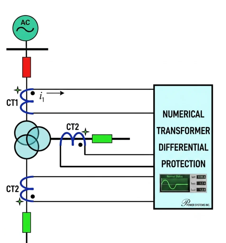
87T is the ANSI/IEC function code for transformer differential protection. It serves as the main protection for transformers by comparing currents entering and leaving the unit. The relay detects internal faults such as winding phase-to-phase/earth faults, inter-turn faults, and bushing faults, and operates within milliseconds when the current balance is disrupted.
The protection zone is defined by CTs on each side of the transformer, ensuring faults inside the zone are cleared and external faults are restrained. To prevent maloperation caused by CT errors and saturation during external faults, a percentage restraint characteristic is applied, so the higher the through-current, the higher the operating threshold. Also, second harmonic restraint blocks tripping during magnetizing inrush to avoid false operation.
Related Transformer Differential Protection Guides
Transformer Differential Protection Working Principle
Transformer Differential Protection Setting
Differential Protection Relay Setting Calculation
Transformer Differential Protection Testing
Differential Protection for Star-Delta Transformer
Differential Protection for Star-Star Transformer
Transformer Overcurrent Protection (ANSI 50/51)
Transformer overcurrent protection (ANSI 50/51) provides backup protection for power transformers against phase faults and short circuits on the transformer windings and connected feeders. ANSI 50 offers instantaneous protection without intentional time delay, while ANSI 51 provides time-delayed protection using inverse-time characteristics.
In transformer protection schemes, 50/51 elements serve as a second line of defense when the main differential protection fails or when faults occur outside the differential zone, such as on downstream feeders.
Time-current coordination with upstream and downstream devices is essential for selective fault clearing. Downstream protection should operate first for feeder faults, with the transformer overcurrent protection providing backup only when needed.
The settings are determined based on transformer impedance, fault levels, and coordination with adjacent protection devices to achieve reliable and selective operation.
Transformer Earth-Fault Protection
Transformer earth fault protection is used to detect winding-to-ground faults and external earth faults, which may not produce sufficient fault current to be detected by phase overcurrent protection.
The protection typically measures zero-sequence current, which flows only during ground faults and can be derived from the vector sum of phase currents or measured directly via a CT installed in the transformer neutral connection.
The implementation of earth-fault protection depends on the transformer neutral grounding arrangement and system configuration. The ANSI 50N/51N function provides instantaneous and time-delayed backup earth-fault protection using residual current from phase CTs, making it suitable for grounded systems where zero-sequence current is present.
Earth-fault protection can be implemented using different schemes depending on transformer grounding and winding configuration.
Restricted Earth-Fault Protection for Transformers
Restricted Earth-Fault (REF) protection is a high-sensitivity protection scheme designed to detect earth faults within a defined zone, typically the transformer winding between the neutral CT and the phase CTs.
Unlike standard earth-fault protection, which measures the overall zero-sequence current of the transformer and may not have a defined boundary, REF employs a differential comparison of currents entering and leaving the protected zone, usually measured by the phase CTs at the line side and the CT in the transformer neutral.
This allows REF to achieve high sensitivity to low-magnitude winding-to-ground faults, which often produce insufficient current for detection by overcurrent elements, while maintaining stability for faults outside the zone, such as external earth faults on the connected system.
REF is particularly effective for transformers with solidly grounded or impedance-grounded neutrals and is often applied in combination with differential protection to provide full coverage for internal earth faults. Its application and configuration depend on transformer grounding arrangement and winding connection.
Transformer Overexcitation Protection (ANSI 24)
Transformer overexcitation protection (ANSI 24) activates when the transformer voltage-to-frequency ratio (V/Hz) exceeds the level for which the magnetic core was designed. Under normal conditions, the core flux density is proportional to V/Hz. When the ratio rises beyond the design limit, the core enters saturation.
This leads to increased magnetizing current, core heating, and mechanical/insulation stress due to stray flux. Overexcitation is typically caused by system overvoltage conditions or underfrequency operation, such as during generator start-up or load rejection.
The ANSI 24 protection function continuously monitors the V/Hz ratio and initiates alarm or tripping when the ratio exceeds set thresholds, preventing core damage and thermal degradation of the transformer.
This protection is particularly important for large power transformers and generator step-up units, where prolonged overexcitation can cause significant damage. The settings are usually coordinated with the transformer design V/Hz capability and system operating conditions.
When Does Overheating Become a Protection Problem?
Types of transformer protection also cover heat, which is slower and less dramatic than a fault. Transformer thermal and overload protection tracks the winding hot-spot from the measured current, and it warns long before any overcurrent threshold would trip. Overload protection is not the same as short-circuit protection. Short-circuit protection responds to high-magnitude fault currents with fast tripping to limit mechanical and thermal stress, while overload protection addresses sustained overcurrent conditions that cause gradual temperature rise and insulation aging. The following table summarizes the typical protection functions for different fault and operating conditions.
| Condition | Typical Protection |
|---|---|
| Short circuit | 50/51 |
| Internal transformer fault | 87T |
| Earth fault | 50N/51N / REF |
| Long-term overload | 49 |
| High winding temperature | Temperature protection |
| Excessive V/Hz | 24 |
Overload Protection (ANSI 49)
ANSI 49 overload protection monitors the transformer thermal condition based on current measurement. It uses a thermal model to calculate the winding hot-spot temperature and operates with a time delay to prevent tripping during temporary overloads, while initiating alarm or trip when the thermal limit is exceeded. It is essential for continuous transformer operation under varying load conditions.
Winding Temperature Protection
Winding temperature protection provides direct or calculated monitoring of the hottest spot in the transformer windings. It uses embedded temperature sensors or thermal models derived from current and oil temperature. High winding temperature indicates overload, cooling failure, or internal faults. The protection initiates alarms, cooling control actions, or tripping to prevent insulation damage.
Oil Temperature Protection
Oil temperature protection is used for oil-immersed transformers to monitor the top-oil temperature. It provides early warning of abnormal thermal conditions, such as overload, cooling system failure, or loss of oil circulation. Alarm and trip thresholds are set based on the transformer manufacturer’s data and operating limits.
Mechanical Transformer Protection Devices
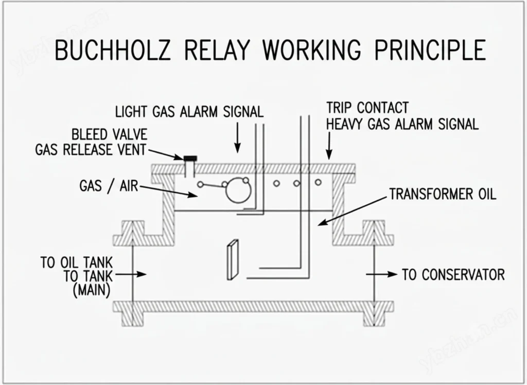
Non-electrical protection covers physical and thermal conditions within the transformer that cannot be detected by electrical protection devices. These protections provide early warning or tripping for mechanical, thermal and insulation-related abnormalities, and they cover the oil-immersed cases electrical detection cannot reach.
Electrical vs mechanical transformer protection is a split by sensing principle, not by priority. A relay sees the fault current. A Buchholz relay or a pressure relief device sees what that current left behind inside the tank.
Buchholz Protection
Transformer Buchholz protection is a gas- and oil-flow-based protection device used for oil-immersed transformers with conservator systems. It detects gas accumulation caused by slow insulation decomposition, as well as rapid oil movement caused by internal arcing faults. The Buchholz relay provides an alarm for gas accumulation and a trip signal for rapid oil flow. It is commonly applied to oil-immersed transformers with conservator systems, subject to transformer design and applicable standards.
Pressure Relief Protection
Pressure relief protection is designed to release excess pressure inside the transformer tank during internal faults. When a fault generates rapid gas production, the tank pressure can rise quickly. The pressure relief device opens to vent the pressure, preventing tank rupture or deformation. Depending on the scheme, it may be configured to provide alarm, trip, or both.
Oil Level Protection
Oil level protection monitors the oil level in the transformer tank or conservator. A low oil level may indicate leakage, oil loss, or a fault condition that affects insulation and cooling. The protection provides alarm indication to allow corrective action before the oil level drops to a critical point.
Temperature Monitoring
Temperature monitoring covers both oil and winding temperature measurements. Oil temperature monitoring measures top-oil temperature to detect overheating, cooling failure, or overload conditions. Winding temperature monitoring measures or calculates hot-spot temperature for thermal protection. Both functions can provide alarm, trip, or cooling control signals, depending on the settings and application.
Transformer Protection by Transformer Type
Transformer type decides which of the types of transformer protection actually matter. A dry-type unit in a plant needs 87T plus a temperature signal. An oil-immersed unit keeps those same electrical elements and adds Buchholz and a pressure relief device on top.
Dry-Type Transformer Protection
Dry-type transformers have no oil, so protection relies on electrical and thermal monitoring. Common protection functions include:
- 50/51 Overcurrent Protection – For phase and earth faults
- Earth Fault Protection – Sensitive ground fault detection depending on neutral grounding
- Overload Protection (49) – Thermal monitoring based on current measurement
- Temperature Protection – Direct winding temperature monitoring via embedded sensors
Oil-Immersed Transformer Protection
Oil-immersed transformers require a broader range of protection, combining electrical and non-electrical functions. Common protection includes:
- 87T Differential Protection – Main protection for internal electrical faults
- Buchholz Protection – Gas and oil flow detection
- REF Protection – Sensitive earth-fault protection where applicable
- 50/51 Overcurrent Protection – Backup protection
- 49 Thermal Overload Protection – Current-based thermal monitoring
- Temperature Monitoring – Oil and winding temperature measurement
- Pressure Relief Protection – Rapid pressure release during internal faults
Two-Winding Transformer Protection
Two-winding transformers require differential protection with CT inputs on both windings. The relay compensates for CT ratio and vector group differences between HV and LV sides. Backup protection is typically provided by overcurrent and earth-fault protection. Non-electrical protection depends on transformer type.
Three-Winding Transformer Protection
Three-winding transformers require differential protection with CT inputs on all three windings. The protection must accommodate more complex current compensation and vector group relationships. Backup overcurrent protection is applied to each winding. Non-electrical protection follows the same principles as for two-winding transformers.
Generator Step-Up Transformer Protection
Generator step-up (GSU) transformers require coordination with generator protection. Additional considerations include:
- 87T Differential Protection – Must coordinate with generator protection
- REF Protection – Sensitive earth fault detection on the generator side
- Overcurrent Protection – Coordinated with generator protection settings
- Transient and Overfluxing Conditions – Protection for generator start-up and abnormal voltage/frequency conditions
For complete protection scheme design, refer to the Power Transformer Protection guide.
Transformer Protection ANSI Codes and Functions Comparison
| Protection | Main Fault / Condition | Electrical / Non-Electrical | Typical Role |
|---|---|---|---|
| 87T | Internal electrical faults | Electrical | Main |
| 50/51 | Phase faults | Electrical | Main/Backup |
| 50N/51N | Earth faults | Electrical | Main/Backup |
| REF | Winding earth faults | Electrical | Sensitive protection |
| 49 | Thermal overload | Electrical/thermal | Monitoring/Protection |
| 24 | Overexcitation | Electrical | Protection |
| Buchholz | Internal gas/oil faults | Non-electrical | Main |
| Pressure Relief | Rapid pressure rise | Non-electrical | Protection |
| Temperature | Overheating | Non-electrical | Alarm/Trip |
| Oil Level | Low oil | Non-electrical | Alarm/Protection |
Conclusion
Types of transformer protection fall into electrical relays and mechanical devices. The transformer protection functions above are specified by device number first, hardware second. Use 87T, 50/51 and earth-fault for faults, Buchholz and PRV for incipient faults.
Technical References
| Source | What it covers | Type | Edition |
|---|---|---|---|
| IEEE C37.91-2021 | Guide for protective relay applications for power transformers; scheme layout behind 87T, 50/51 and 49 | Standard | 2021 |
| ANSI/IEEE C37.2-2022 | Functional device numbers: 87T, 50/51, 50N/51N, 87N, 24 and 49, including the non-electrical assignments | Standard | 2022 |
| IEC 60255-187-1:2021 | Functional requirements for differential protection of transformers and reactors | Standard | 2021 |
| IEC 60255-1:2022 | Measuring relays and protection equipment: general requirements and the type-test clauses behind the 24 and 49 classes | Standard | 2022 |
| IEC 60076-11:2018 | Dry-type transformers: thermal and voltage capability limits behind the dry-type section above | Standard | 2018 |
Related Reading
- Power transformer protection: schemes and relays
- Transformer fault types, causes and symptoms
- Transformer protection devices with ANSI codes
FAQ
Q1. What are the main types of transformer protection?
The main transformer protection types include electrical protection (e.g., differential, overcurrent, earth fault, REF, overexcitation) and non-electrical protection (e.g., Buchholz, temperature, pressure, oil level monitoring). The actual combination depends on transformer type, size, voltage level, and application.
Q2. What is the main protection for a power transformer?
The main protection for a power transformer is typically differential protection (ANSI 87T), which provides fast and selective detection of internal winding faults by comparing currents entering and leaving the transformer.
Q3. What is ANSI 87T transformer differential protection?
ANSI 87T is the standard device number for transformer differential protection. It operates on the current balance principle and trips when an internal fault produces a differential current.
Q4. What is the difference between transformer differential and overcurrent protection?
Differential protection compares currents on both sides of the transformer and provides fast, zone-selective clearing of internal faults. Overcurrent protection responds to current magnitude and serves as backup protection for faults not detected by differential protection or faults on connected feeders.
Q5. What is transformer earth-fault protection?
Transformer earth-fault protection detects ground faults in transformer windings or connected systems. It typically uses zero-sequence current measurement from phase CTs (50N/51N) or a neutral CT, depending on the transformer grounding arrangement.
Q6. What is Buchholz protection?
Buchholz protection is a non-electrical protection device used for oil-immersed transformers with conservator systems. It detects gas accumulation (alarm) and rapid oil movement (trip) caused by internal faults.
Q7. What is transformer overexcitation protection?
Overexcitation protection (ANSI 24) protects the transformer against excessive voltage-to-frequency ratio (V/Hz), which can cause core saturation, overheating, and insulation damage.
Q8. What is REF protection for a transformer?
Restricted earth-fault (REF) protection is a sensitive protection scheme for detecting earth faults within a defined zone, typically the transformer winding. It provides high sensitivity for low-magnitude winding-to-ground faults.
Q9. What protection is used for dry-type transformers?
Dry-type transformers typically use overcurrent protection (50/51), earth fault protection, overload protection (49), and winding temperature monitoring. They do not use oil-based protection devices such as Buchholz.
Q10. What protection is used for oil-immersed transformers?
Oil-immersed transformers typically use a combination of differential protection (87T), overcurrent (50/51), earth fault (50N/51N), REF, Buchholz, temperature monitoring, pressure relief, and oil level monitoring.
Q11. How are transformer protection functions coordinated?
Protection functions are coordinated by zone and time grading. Main protection (e.g., 87T) provides fast clearing for faults within its zone. Backup protection (e.g., 50/51) operates with time delays for faults not cleared by main protection or outside its zone. Non-electrical protection provides additional coverage for conditions not detected by electrical protection.
Q12. How do I select a transformer protection relay?
Selection factors include transformer MVA rating, voltage levels, winding configuration, transformer type (dry or oil), CT inputs, required protection functions, binary I/O, communication protocols, fault recording capability, and compliance with project standards. The step-by-step sequence, including CT ratio and slope checks, is covered in how to select a transformer protection relay.



About Author

Hello, I'm Leno Zhang. I have 15 years of experience in the power relay protection industry with extensive pre-sales and after-sales project experience. Our company specializes in various complete sets of relay protection and automation equipment. I can assist customers in solving all practical on-site project challenges and provide optimal integrated solutions.
Tell Us Your Requirement
High Quality
Stable performance, reliable design, ensuring safe operation for power system protection and grid stability.
Fast Delivery
Timely delivery to support your urgent orders and project schedules efficiently and professionally at any time.
Best Warranty
Professional Warranty: Reliable after-sales support for stable relay protection and long-term customer satisfaction.