

-
Leon Zhang sales consultant
-
Email: zxl635973785@gmail.com
-
Phone/WhatsApp: +86 13655813266
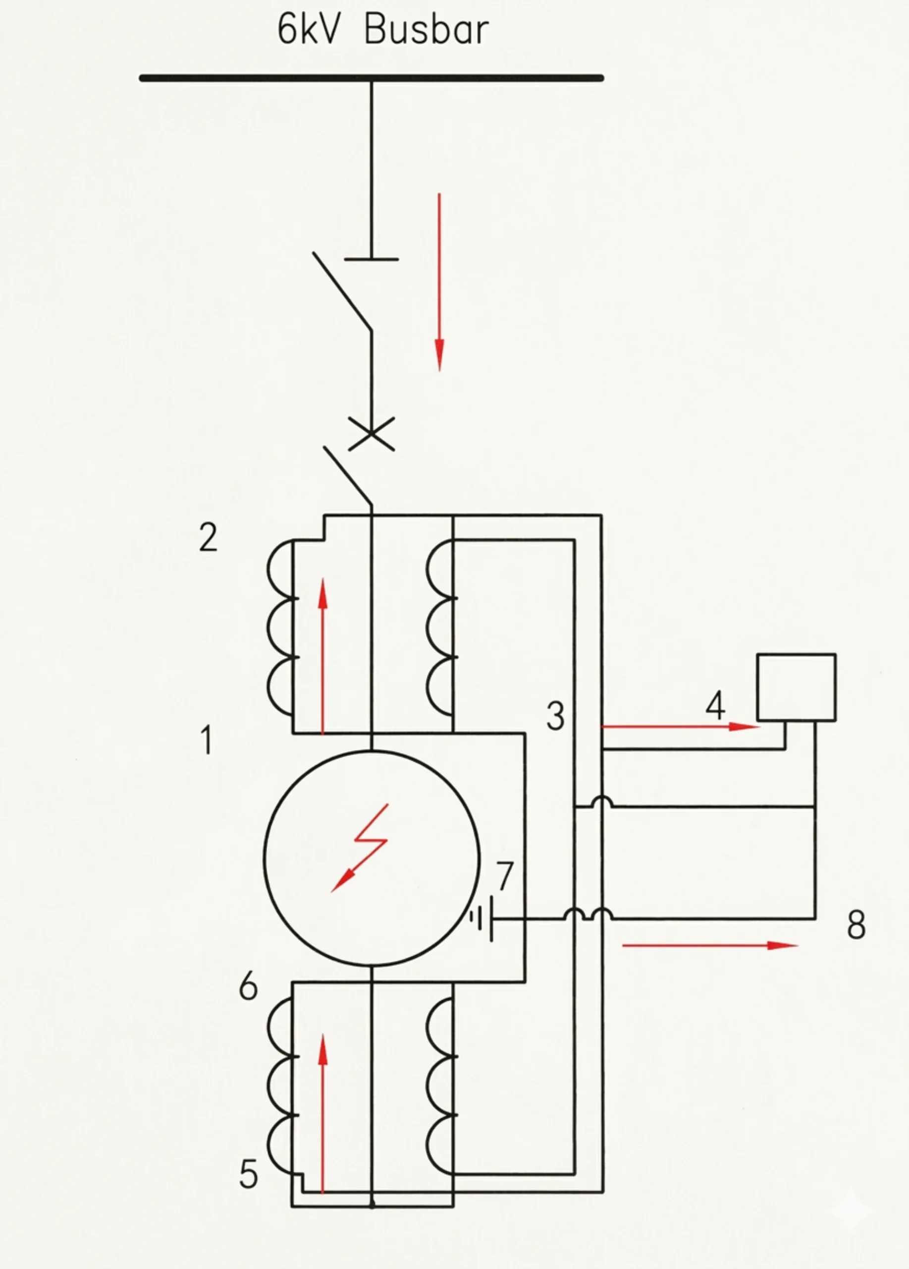
Generator Differential Protection 87G: Principles, Schemes, Settings and Testing
What Is Generator Differential Protection?
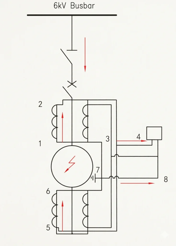
Generator differential protection 87G is a unit protection scheme: it compares the current measured at the generator terminal CTs with the current measured at the neutral CTs, and it trips only when the difference points to a fault inside that zone. Pickup is normally set at 0.1–0.3 × rated current, above the maximum unbalance current the machine shows in healthy operation.
Written by Leon Zhang, Protection Application Engineer · Technical review by Li Ming, Electrical Engineer · Last reviewed September 2026
The protection operates by comparing currents entering and leaving the protected zone. Two sets of current transformers are installed—one at the generator terminal and one at the neutral side. The relay continuously monitors both signals and calculates the difference between them.
Under normal conditions or during external faults, the currents at both CTs are equal, resulting in a net differential current of approximately zero. The relay remains stable and does not operate.
When a stator internal fault occurs—such as a phase-to-phase short circuit, a turn-to-turn fault, or insulation failure—the symmetry is disrupted. Fault current flows only within the faulted zone, and the currents measured by the two CTs become unequal. This imbalance produces differential current. Once it exceeds the preset threshold, the relay issues an instantaneous trip command, isolating the generator from the system.
Modern 87G relays incorporate dual-slope characteristics to ensure stability during external faults with CT saturation, while maintaining high sensitivity for internal faults. Second-harmonic restraint is also applied to prevent false tripping during generator start-up inrush currents.
That is the whole principle: balanced currents in, no trip; unbalanced currents in, trip. Slope setting, CT class and harmonic restraint exist to keep that comparison honest when CTs saturate or the machine is energized.
Key Takeaways
- The zone is set by CTs. Terminal-side and neutral-side CTs define the boundary. 87G answers only for what happens between them.
- Pickup sits above normal unbalance. Typically 0.1–0.3 × rated current, checked against unbalance current measured in service.
- Stability comes from restraint. Dual-slope percentage restraint (first slope typically 20–40%, second 50–80%) is what holds the relay stable through external faults with CT saturation.
- Most commissioning failures are CT problems. Reversed polarity and ratio mismatch cause more unwanted 87G operations than relay setting errors do.
87G Protection Principle: Current Comparison Across the Stator Zone
Generator differential protection (ANSI 87G) operates on a simple current comparison principle, continuously monitoring currents at both ends of the stator windings to detect internal faults. The full derivation is in how generator differential protection works.
The Core Principle
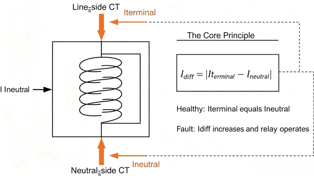
Idiff = |Iterminal − Ineutral|
Where Iterminal is measured at the line-side CTs and Ineutral at the neutral-side CTs. Under healthy conditions, these currents are equal, keeping Idiff near zero.
Normal Load & External Faults
During normal operation, current flows through the generator and out to the system. Both CTs measure the same current.
Iterminal ≈ Ineutral → Idiff ≈ 0
The relay remains stable and does not trip.
For external faults outside the generator, the fault current passes through the stator windings, but both CTs still see balanced currents. The relay recognizes this as an external event and does not operate.
Internal Stator Fault
When a fault occurs inside the stator windings—such as a phase-to-phase short circuit, turn-to-turn fault, or insulation breakdown—the balance is broken. Fault current flows only within the faulted zone, and the two CT readings become unequal.
Iterminal ≠ Ineutral → Idiff exceeds threshold
The relay instantly issues a trip command, opening the generator breaker and isolating the generator from the system within milliseconds.
Generator Differential Protection Scheme
Generator differential protection schemes are mainly divided into four types: Overall Differential Protection, Split-Phase Differential Protection, High-Impedance Differential Protection, and Low-Impedance Differential Protection. CT arrangements and wiring for each option are covered in the 87G scheme guide.
Overall Differential Protection
Overall Differential Protection is the most basic scheme. It compares currents measured by CTs on the neutral side and line side of the generator to detect internal faults. Under normal conditions, the currents are balanced, and differential current ≈ 0. During internal faults, the currents become unequal, differential current increases, and the relay trips. Modern schemes incorporate dual-slope restraint and second-harmonic restraint to handle CT saturation and inrush currents.
Split-Phase Differential Protection
Split-Phase Differential Protection (transverse differential protection) is specifically designed for generators with multi-branch windings per phase. It compares currents between different branches within the same phase. Under normal conditions, all branch currents are equal. When a turn-to-turn short circuit or ground fault occurs in one branch, the current in that branch differs from the others, and the protection operates. This scheme is suitable for large hydro units but may have protection blind spots, so it is typically used in combination with other schemes.
One boundary is worth stating: on a single-branch machine a turn-to-turn fault can produce differential current below the 87G pickup. The overall scheme will not see every stator fault. That is why large hydro units add split-phase protection, and why 100% stator earth-fault protection is specified separately.
High-Impedance Differential Protection
High-Impedance Differential Protection is based on voltage detection. A high-value resistor is connected in series with the CT secondary circuit, converting the differential current into a voltage for detection. During normal or external fault conditions, the differential current is very small, the voltage drop across the resistor is low, and the protection does not operate. During internal faults, the differential current increases, the voltage drop crosses the setting, and the relay trips immediately. Its key advantage is excellent stability during external faults, making it suitable for large generators, multi-generator parallel systems, and other high-security applications.
Low-Impedance Differential Protection
Low-Impedance Differential Protection is the most common scheme for medium-voltage generators, typically implemented as dual-slope percentage differential protection. CTs are connected directly to the relay’s low-impedance inputs. The protection determines operation by calculating the ratio of differential current to restraint current. Its advantages are flexible configuration and high sensitivity. Modern relays incorporate multi-slope restraint curves and harmonic blocking to handle CT saturation and inrush currents.
Comparison of the Four Schemes
| Scheme | Core Principle | Main Application | Key Advantage |
|---|---|---|---|
| Overall Differential | Current comparison between neutral and line CTs | General generators | Simple principle, wide application |
| Split-Phase Differential | Current comparison between branches of the same phase | Large hydro units with multi-branch windings | Detects turn-to-turn faults |
| High-Impedance Differential | Differential voltage detection | Large generators, busbars, multi-machine systems | Excellent external fault stability |
| Low-Impedance Differential | Percentage differential (dual-slope) | Medium-voltage generators, industrial sites | Flexible configuration, high sensitivity |
87G Scheme Configuration: CT Polarity, Ratio and Saturation
CT configuration directly affects the reliability and sensitivity of generator differential protection. This section provides key points for CT selection and configuration; 87G CT configuration is treated in depth in a separate article.
CT Configuration Overview
| Item | Requirement |
|---|---|
| Terminal side CT | Generator terminal |
| Neutral side CT | Generator neutral |
| Main function | Detect internal stator faults |
| CT polarity | Must be correctly matched |
| CT ratio | Must be matched / compensated |
| CT saturation | Must be considered |
| Relay input | Three-phase differential current |
CT Polarity
Incorrect CT polarity is the most common root cause of commissioning issues. If one CT is connected with reversed polarity, the currents from both sides will be 180° out of phase, producing a false differential current even under normal load—leading to nuisance tripping or reduced sensitivity.
Verification method: Perform an injection test during commissioning to confirm the phase relationship of currents from both CTs; digital relays typically include built-in polarity verification features.
Key recommendation: Always verify polarity after commissioning and any work affecting the secondary circuits.
CT Ratio
The CT ratio must be carefully selected to ensure that the secondary current falls within the relay’s nominal input range (1A or 5A) at rated load. If ratios on both sides do not match, the relay can compensate using internal ratio matching.
Key recommendation: Select ratios that minimize mismatch and utilize the relay’s compensation features for accurate balance.
CT Saturation
During severe external faults, fault current can reach 20–30 times the rated value, potentially causing CT saturation. Saturated CTs produce distorted secondary currents, which can create a false differential current and cause unwanted tripping.
Mitigation strategies:
| Strategy | Description |
|---|---|
| Proper sizing | Select CTs with adequate knee-point voltage and accuracy class for the maximum expected fault current |
| Relay characteristics | Use relays with dual-slope restraint characteristics |
| Burden reduction | Use short leads and appropriate wire gauge to reduce secondary burden |
Key recommendation: Always verify CT performance against maximum fault levels, and coordinate relay settings with CT characteristics.
Checklist
| Item | Status |
|---|---|
| CT polarity | Verified |
| CT ratio | Matched / compensated |
| CT accuracy class | Meets protection requirements |
| Knee-point voltage | Adequate |
| CT burden | Within limits |
| Relay settings | Coordinated with CT characteristics |
Slope and Percentage Restraint: How 87G Stays Stable on External Faults
Modern differential protection resolves the conflict between sensitive operation during internal faults and stable operation during external faults through the Percentage Restraint principle. The key lies in the Slope setting.
Key Concepts
| Concept | Definition | Purpose |
|---|---|---|
| Differential Current (Idiff) | Difference between currents from both CTs | Indicates internal faults |
| Restraint Current (Irestraint) | Average (or maximum) of the two CT currents | Reflects through-current; provides restraint |
| Slope | Angle of the operating characteristic curve | Determines the operating threshold |
Operating Criterion
Idiff > Slope × Irestraint + Pickup
The higher the fault current, the higher the required differential threshold—increased restraint during external faults, maintained sensitivity during internal faults.
Dual-Slope Characteristic
| Slope Section | Application | Characteristic |
|---|---|---|
| First Slope (Low) | Normal operation, minor internal faults | High sensitivity |
| Second Slope (High) | External faults, potential CT saturation | Strong stability, prevents maloperation |
CT Saturation and External Fault Stability
During external faults, massive through-current can cause CT saturation, producing distorted secondary currents that create false differential current. Restraint current increases with through-current, raising the operating threshold accordingly—even if CT saturation produces some differential current, the relay remains stable as long as it stays below the restraint threshold.
The second slope covers exactly this case. In the high-current region it raises the operating threshold faster than the spurious differential current grows, so the relay holds.
87G Settings: Pickup, Slope, High-Set and CT Ratio Compensation
Generator differential protection settings are critical to ensuring protection selectivity, sensitivity, and reliability. The following parameters are conceptual only. Actual settings must be calculated based on specific project parameters and the relay manufacturer’s manual. There are no universal parameters applicable to all generators. Parameter-by-parameter guidance is in 87G settings.
Differential Pickup Setting
Definition: The differential pickup threshold—when differential current exceeds this value, the protection enters its operating logic.
Principle: Must be set above the maximum unbalance current during normal operation. Typically 0.1–0.3 × rated current.
Basis: Generator rated current, CT accuracy class, and relay measurement precision.
Slope Setting
Definition: The ratio of differential current to restraint current—the core parameter of percentage restraint.
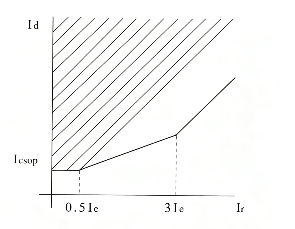
Principle:
- First Slope: Typically 20%–40% – ensures sensitivity
- Second Slope: Typically 50%–80% – ensures external fault stability
Basis: CT saturation characteristics, maximum system external fault current, and relay characteristic curves.
High-Set Differential Protection
Definition: A non-restrained high-speed element for fast clearing of severe internal faults.
Principle: Set well above the pickup value, typically 3–8 × rated current. No restraint is applied, and it is not affected by CT saturation.
Basis: Minimum expected internal fault current (to ensure operation) and maximum external fault current (to prevent maloperation).
CT Ratio Compensation
Definition: Internal relay mathematics to eliminate unbalance current caused by mismatched CT ratios on both sides.
Basis: Neutral side CT ratio, terminal side CT ratio, and the relay’s allowable compensation range.
Setting Verification
Verification Methods:
| Item | Purpose |
|---|---|
| Fault current calculation | Confirm settings operate reliably |
| CT saturation assessment | Confirm slopes can handle CT saturation |
| Sensitivity check | Confirm sufficient sensitivity for high-impedance faults |
| External fault stability | Confirm no maloperation during external faults |
| Secondary injection test | Verify actual operating values match settings |
Important Reminders
| Key Point | Note |
|---|---|
| No universal parameters | Each generator must be calculated individually |
| Consult the manual | Different relays have different setting methods |
| Fault analysis required | System fault current calculation must be completed first |
| Field verification required | Settings must be validated by injection testing |
All setting work must be performed by qualified protection engineers.
87G Testing: Polarity, Ratio and Secondary Injection
Generator differential protectiontesting is a critical step in verifying the correctness, reliability, and security of the protection system. Testing covers the entire process from CT circuit verification to complete trip validation, ensuring that the protection operates reliably during internal faults and remains stable during external faults. Procedures and acceptance criteria are set out in 87G testing.
CT Polarity Test
Purpose: To verify that the CT polarity connections on both the generator neutral side and terminal side are correct.
Test Methods:
- DC Inductive Method: Apply a DC pulse to the CT primary side and observe the induced voltage direction on the secondary side to determine polarity
- Primary Injection Method: Inject a single-phase current into the generator circuit and measure the phase relationship of the secondary currents from both CTs
- Relay Polarity Indication: Some digital relays have built-in polarity verification functions to assist in judgment
Acceptance Criteria: When CT polarity is correct, the secondary currents are in phase, and the differential current is near zero. Reversed polarity will cause increased differential current and may trigger maloperation during normal operation.
Key Reminder: CT polarity errors are the most common root cause of commissioning issues in differential protection and must be verified before system energization.
CT Ratio Test
Purpose: To confirm that the actual CT ratio matches the nameplate rating, ensuring measurement accuracy.
Test Methods:
- Primary Injection Method: Inject a known current on the primary side, measure the secondary output, and calculate the actual ratio
- Comparison Method: Connect the CT under test in series with a reference CT of known accuracy and compare secondary outputs
Acceptance Criteria: The error between measured ratio and nameplate ratio should be within the CT accuracy class tolerance (typically ±0.5% to ±1%).
Key Reminder: Excessive ratio errors will increase differential unbalance current during normal operation, potentially reducing protection sensitivity or causing maloperation.
Secondary Injection Test
Purpose: To verify relay measurement accuracy, setting values, and logic functions.
Test Methods:
- Use a relay test set to inject simulated CT secondary current signals into the relay
- Inject single-phase current to simulate differential current and verify pickup settings
- Inject currents on both sides simultaneously to simulate different operating conditions and verify slope characteristics and restraint functions
Acceptance Criteria: The relay’s measured operating values should match the settings within the relay’s accuracy tolerance; operating times should meet design expectations.
Key Reminder: Secondary injection testing should be performed at the protection panel, covering the complete circuit from relay input terminals to output contacts.
87G Generator Differential Protection Relay
For projects requiring numerical 87G protection, our generator differential protection relay is designed for generators up to 100 MW and provides phase-separated differential protection, high-speed fault detection and CT open-circuit detection.
View Generator Differential Protection Relay 87G
What to Look for in a Generator Differential Protection Supplier
Choosing the right supplier affects the relay you install and how the machine behaves for the next twenty years. The following evaluation criteria focus on technical capability and service quality rather than brand origin; 87G relay selection is covered separately.
Key Evaluation Dimensions
| Dimension | Key Considerations | Priority |
|---|---|---|
| Technical Support | Professional engineering support, commissioning and troubleshooting capability, emergency response time | ★★★ |
| Documentation | Manual completeness, setting calculation guides, test reports, language support | ★★★ |
| Relay Configuration | Pre-configuration based on generator parameters, software usability, setting lists | ★★ |
| FAT | Test scope, witness options, deviation handling process | ★★★ |
| Communication | Protocol support, SCADA integration experience, mapping documentation | ★★ |
| Spare Parts | Critical parts list, lead time, product lifecycle support | ★★ |
| After-Sales Support | On-site commissioning assistance, training, software upgrades, warranty terms | ★★★ |
| Project Experience | Track record with similar capacities, references from hydro/thermal/gas/industrial projects | ★★★ |
Key Questions to Ask
Technical Support:
- Does the support team have specific expertise in generator differential protection?
- What is the committed response time for technical inquiries?
Documentation & Configuration:
- Do they provide recommended settings based on your generator parameters?
- Is documentation available before delivery for advance study?
Testing & FAT:
- Does the standard FAT scope cover all protection functions?
- Can you witness the test or request video records?
Spares & After-Sales:
- What after-sales support is included in the standard package?
- What is the lead time for critical spares? How long is product support available?
Project Experience:
- Can they provide references from similar projects?
- What challenges did they encounter and how were they resolved?
Selection Recommendation
A qualified supplier should demonstrate:
- Solid engineering capability – Deep understanding of generator protection principles
- Transparent delivery process – Complete documentation and test procedures
- Full lifecycle service commitment – Technical support from selection through commissioning to maintenance
- Proven field experience – Successful delivery records for similar projects
Before making a decision, we recommend evaluating potential suppliers against the dimensions above.
FAQ
1. What is generator differential protection 87G?
Generator differential protection 87G is a primary protection function used to detect internal phase-to-phase and other stator winding faults within the protected generator zone. It compares the currents measured by CTs at the generator terminal and neutral ends. Under normal operating conditions and external faults, the currents remain substantially balanced. An internal fault produces differential current that can cause the 87G protection to operate.
2. How does generator differential protection work?
Generator differential protection compares the current entering and leaving the protected generator zone. Under normal load or an external fault, the differential current remains low. When an internal stator fault occurs, the current balance is disrupted and the relay sees differential current. If the differential current exceeds the configured operating characteristic, the relay issues a trip command to disconnect the generator.
3. What CTs are required for generator differential protection?
Generator differential protection normally uses CTs at the generator terminal and neutral ends to define the protected stator zone. CT ratio, accuracy class, polarity, excitation characteristics, secondary burden, and wiring must be properly coordinated. CT mismatch and saturation can produce unwanted differential current, so CT selection and polarity verification are important parts of 87G protection design and commissioning.
4. What causes false trips in generator differential protection?
False 87G operation can result from CT saturation during external faults, incorrect CT polarity, CT ratio mismatch, wiring errors, excessive secondary circuit resistance, or inappropriate differential protection slope settings. During commissioning, CT polarity and ratio checks, secondary injection testing, and differential protection stability tests should be performed to verify secure operation.
5. How is generator differential protection 87G set?
87G settings depend on the generator rated current, CT ratios, CT characteristics, expected fault current, relay operating characteristic, and protection coordination requirements. Typical setting considerations include differential pickup, percentage restraint or slope, high-set differential protection, CT ratio compensation, and stability requirements during external faults. Final settings should be calculated from the actual generator and protection system data rather than applying a universal setting.
6. What is a generator differential protection stability test?
A generator differential protection stability test verifies that the 87G relay remains stable when current passes through the protected zone during normal operation or an external fault. The test checks whether CT mismatch, wiring errors, or CT saturation could create enough differential current to cause an unwanted trip. Stability testing is an important part of FAT and site commissioning.
7. What is the difference between generator differential protection and generator-transformer differential protection?
Generator differential protection 87G primarily protects the generator stator winding between the generator terminal and neutral CTs. Generator-transformer differential protection covers a wider protection zone that may include the generator, step-up transformer, and associated connections, depending on the protection scheme. The CT arrangement, protected zone, relay settings, and fault coverage are therefore different. See 87G vs 87GT for the zone-by-zone comparison.
8. How do I choose a generator differential protection scheme?
When selecting a generator differential protection scheme, consider the generator capacity and voltage, stator winding configuration, CT arrangement, required sensitivity, external-fault stability, protection slope, and integration with the overall generator protection system. The selected scheme should be verified through protection calculations, CT checks, and commissioning tests.
Conclusion: What to Check Before You Specify 87G
Generator differential protection 87G is still the fastest way to clear an internal stator fault, and its logic is simple enough to audit: two currents, one comparison. What decides whether it performs in service is usually not the relay but the CTs behind it: polarity, ratio match, knee-point voltage and secondary burden, plus a slope setting that has been checked against the maximum external fault current. The two review steps belong together: 87G settings and testing are checked as one package, because a setting that has never been injected is still only a calculation.
Before a specification goes out, confirm three numbers: the CT knee-point voltage at the maximum through-fault current, the pickup against unbalance current measured on the machine, and the stability check at that same fault level. If any one of the three is missing from the setting calculation, the scheme is not finished.
Get the settings reviewed before FAT: send the generator rating, CT data and single-line diagram, and we will return a setting proposal with a test scope. Request 87G application support.
Technical References
| Source | What it covers | Type | Edition |
|---|---|---|---|
| IEEE C37.102 | AC generator protection guide: 87G schemes, CT requirements, setting practice | Standard | 2006 |
| ANSI/IEEE C37.2 | Device function numbers, including 87 and the G suffix for generators | Standard | 2008 (confirm current edition) |
| Relay manufacturer application manual | Pickup range, slope options, CT ratio compensation limits | Manufacturer | Per relay model |
| Manufacturer FAT and type-test records | Operating times, pickup accuracy, stability checks | First-party data | To be added: test conditions + year |



About Author

Hello, I'm Leno Zhang. I have 15 years of experience in the power relay protection industry with extensive pre-sales and after-sales project experience. Our company specializes in various complete sets of relay protection and automation equipment. I can assist customers in solving all practical on-site project challenges and provide optimal integrated solutions.
Tell Us Your Requirement
High Quality
Stable performance, reliable design, ensuring safe operation for power system protection and grid stability.
Fast Delivery
Timely delivery to support your urgent orders and project schedules efficiently and professionally at any time.
Best Warranty
Professional Warranty: Reliable after-sales support for stable relay protection and long-term customer satisfaction.