
-
Leon Zhang Sales Manager
-
Email: sale@relayprotect.com
-
Phone/WhatsApp: +86 13655813266
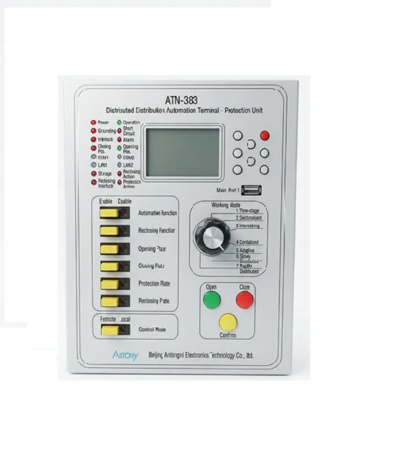
Distributed DTU | IEC 61850 Distribution Automation Terminal
This Distributed DTU is designed for protection, measurement, control and communication of interval units in 10kV and below ring main units.
Communication Mode
Optional: RS-485, CAN bus, Ethernet, IEC 60870-5-103 (IEC-103), IEC 61850
Send your requirements, we will quote for you within 12 hours
MOQ: 1 setLead time: 7-15 working daysPayment: T/T, L/C, Western Union, PayPalWarranty: 12 monthsTrade terms: EXW, FOB, CIF, DDUCertification: CEDifferent rating, protocol or mounting: send the specification and we confirm before you order.
Description
What is an IEC 61850 distributed DTU?
A distributed DTU is a distribution automation terminal split into a head unit and several remote acquisition units placed at the switchgear, connected by fibre or a process bus, so a ring main unit or a multi-bay distribution station can be automated without pulling every CT and status wire back to one cabinet. The distributed arrangement is the point: in a retrofit the cable trench is already full, and placing the acquisition unit at the switchgear removes most of the new cabling. The head unit runs the fault detection, the isolation logic and the communication to the master station over IEC 61850 or IEC 60870-5-104. Typical duty is a 10 kV ring main unit, an outdoor distribution station or a compact substation where fault passage indication and remote isolation are required. Single-line diagram review at order; quotation within 12 hours, MOQ 1, 7-15 working days.
Overview of Distributed DTU
- This DTU is designed for protection, measurement, control and communication of interval units in 10kV and below ring main units.
- Equipped with full functions of protection, measurement, control and communication monitoring, it works with circuit breakers and load switches to safeguard 10kV and below power lines and feeders.
- It can quickly isolate faulty sections, narrow power outage scope and resume power supply efficiently, ensuring stable and safe operation of distribution networks.
For one integrated unit covering a whole switching station or prefabricated substation, see the DTU-380H integrated DTU.
Functions
- The feeder terminal (protection & control unit) supports remote signalling, remote measurement, remote control and protection logic for corresponding bays. It adopts three-stage protection, master station centralized automation, voltage-time and voltage-current based feeder automation schemes.
- Applicable to all positions of 10kV distribution lines, including ring, radial and branch lines, low-resistance grounding and arc suppression coil grounding systems, as well as circuit breaker and load switch cabinets.
- It enables local fault isolation and self-healing. Three-remote data and fault messages can be uploaded to distribution dispatching master station to realize remote fault disposal and build fault location system.
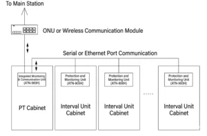
Differences Between Distributed DTU and Centralized DTU
Centralized DTU
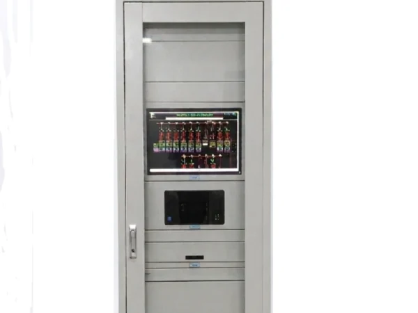
- It adopts an integrated, centralized installation design, with all data acquisition, communication and processing units integrated into a single enclosure, which is placed in the terminal room.
- It features a compact structure but has poor scalability (replacing the entire unit is required when adding circuits), a high risk of single-point failure (a fault in the main control unit will paralyze the entire station), and requires a large number of cables routed from switch cabinets to the enclosure.
DTU
- It adopts a modular, decentralized installation design. Each functional unit (analog measurement, status monitoring, remote control modules) is independent, installed locally in the secondary compartment of the switch cabinet, and connected via an internal bus.
- Its advantages include strong redundancy (a fault in a single module does not affect others), support for hot swapping, significant cable savings, and flexible scalability (modules can be added as needed).
- Therefore, distributed DTU has become the mainstream choice for modern smart distribution networks.
Technical Specifications
| Application | Ring main units, switching stations, distribution rooms and box substations on 10 kV and below distribution networks |
| Functions | Remote signalling, remote measurement, remote control and bay protection |
| Rated DC supply | DC 24 V or DC 48 V, specified at order |
| Rated AC voltage | 57.74 V / 100 V / 220 V / 380 V |
| Rated AC current | 5 A or 1 A, specified at order |
| Rated frequency | 50 Hz |
| Voltage overload | 2 times rated voltage, continuous |
| Current overload | 2 times rated current continuous; 20 times rated current for 1 s |
| Power consumption | below 0.5 VA per phase, voltage and current circuits |
| Current setting range | 0.1 In to 20 In, step 0.01 A |
| Voltage setting range | 1 V to 440 V, step 0.1 V |
| Time delay setting range | 0.00 s to 99.99 s, step 0.01 s |
| Setting error | current below ±3%; voltage below ±3%; time delay within 50 ms or ±2% |
| Measurement accuracy | analog quantities ±0.5% of rated value; power ±0.5%; frequency ±0.02 Hz |
| SOE resolution | 2 ms or better |
| Remote control accuracy | not lower than 99.99% |
| Insulation resistance | 100 MΩ or more at 500 V |
| Dielectric strength | 2 kV 50 Hz for 1 minute on power, AC and output circuits; 1 kV on input circuits |
| Impulse voltage | 5 kV standard lightning impulse |
| Contact rating | DC 250 V / 1 A, 50 W breaking capacity; AC 250 V / 2 A, 250 VA; 5 A continuous |
| Immunity | GB/T 14598.13 class III 1 MHz burst; GB/T 14598.14 8 kV electrostatic discharge; GB/T 14598.9 class III radiated field; GB/T 14598.10 class A fast transient; IEC 60255-22-5 surge; IEC 60255-22-6 conducted disturbance |
| Operating temperature | -40 °C to +70 °C |
| Storage temperature | -40 °C to +85 °C |
| Relative humidity | up to 90%, no condensation |
| Altitude | up to 2000 m, 80 kPa to 110 kPa |
| Analog inputs per main unit | up to 16 voltage, 36 current and 8 DC channels |
| Telesignals per main unit | up to 91 |
| Remote control outputs per main unit | up to 24, controlling 12 circuit breakers |
| Chassis | 4U, 19 inch, up to 12 plug-in modules |
| Ethernet ports | 2 x 10/100BASE-T |
| Serial ports | 6 ports: 2 x RS-232, 2 x RS-232/RS-485, 2 x RS-485 |
| Field bus | 1 x CAN, for cascading main units |
| Time synchronization | IRIG-B (DC) |
| Wireless option | 4G or GPRS |
| Protocols | IEC 60870-5-101 (2002 edition) and IEC 60870-5-104 |
| Protection functions | three-stage overcurrent; overload, trip or alarm; single-shot three-phase reclosing; post-acceleration; two-stage zero-sequence overcurrent; voltage and zero-sequence voltage alarm |
| Panel dimensions | 2260 x 800 x 600 mm, or as required |
| Battery and power management | one group of battery activation remote control, with intelligent power supply and battery charge management |
Configuration Options
| Item | 6 bays | 12 bays | 18 bays | 24 bays |
|---|---|---|---|---|
| Bays covered | 6 | 12 | 18 | 24 |
| Telesignals (YX) | 42 | 84 | 126 | 168 |
| Remote control outputs (YK) | 6 | 12 | 18 | 24 |
| Voltage inputs | 8 | 16 | 24 | 32 |
| Current inputs | 18 | 36 | 54 | 72 |
| DC analog channels | 4 | 8 | 12 | 16 |
| Main units, 4U x 19 inch | 1 | 1 | 2 | 2 |
FAQ
Q1: What is a Distributed DTU?
A: A Distributed DTU (Distributed Distribution Terminal Unit) is a modular, decentralized terminal for distribution automation, used in smart grids to monitor and control switchgear, feeders, and ring main units.
Q2: What is the difference between Distributed DTU and Decentralized DTU?
A: They refer to the same concept. Distributed DTU is the standard term; Decentralized DTU emphasizes the non-centralized, distributed architecture, ideal for smart grid modernization.
Q3: What is Smart Grid DTU used for?
A: Smart Grid Distributed DTU enables real-time monitoring, fault detection, isolation, and restoration in smart grids. It supports feeder automation, remote control, and data communication for reliable grid operation.
Q4: What is FTU DTU / Feeder Terminal Unit DTU?
A: Feeder Terminal Unit DTU (FTU DTU) integrates distributed DTU functions with feeder protection and control. It is deployed on overhead lines and feeders to handle faults, reconfiguration, and load management.
Q5: What are the benefits of a Compact DTU?
A: A Compact Distributed DTU offers small footprint, low power consumption, and easy installation. It is suitable for space-limited substations, ring main units, and secondary distribution automation applications.
Q6: Where can I use Distributed DTU ?
A: Distribution Automation DTU is widely used in urban/rural distribution networks, smart substations, ring main units, industrial parks, and renewable energy grid connections.
Q7: Does Distributed DTU support standard communication protocols?
A: Yes. Most Distributed DTU / Decentralized DTU support IEC 61850, IEC 60870-5-104, Modbus, and Ethernet, ensuring interoperability with SCADA and smart grid systems.
Q8: How do I place an order?
A: Send your specification through the contact form, by email to sale@relayprotect.com or on WhatsApp. We check the rating, the protocol and the wiring against your application, confirm the model, and return a quotation. No account or registration is needed.
Q9: What is the minimum order quantity?
A: The minimum order quantity is one unit. A single unit can be ordered for evaluation or for a pilot installation, and project quantities are quoted separately.
Q10: What is the lead time?
A: Standard models ship in 7 to 15 working days after the order is confirmed and payment is received. Custom ratings, protocols or mounting arrangements are confirmed in writing before the order is placed, so the delivery date is known in advance.
Q11: Which payment methods and trade terms do you accept?
A: Payment by T/T, L/C, Western Union or PayPal. Trade terms are EXW, FOB, CIF and DDU. Every relay carries a 12-month warranty.
What one distributed DTU covers on a ring main unit
Each unit sits in the secondary compartment of the switch cabinet and covers one group of bays: analog measurement, status monitoring and remote control for that set of circuits, plus the protection logic for the bay. Because the units are independent, a fault in one does not stop the others, and a module can be replaced without taking the whole installation out of service.
On a 10kV ring main unit the units work with circuit breakers and load switches to isolate the faulty section and restore supply to the healthy part of the feeder. Three remote data and fault messages go to the distribution dispatching master station, so the fault is handled from the control room instead of by a crew driving to each ring main unit.
Cabling is the practical difference on a retrofit. Centralized equipment brings every signal back to a terminal room, and that is where most of the civil and cable work sits. Distributed units are wired locally inside the switch cabinet and joined by an internal bus, which is why the modular layout has become the usual choice for smart distribution networks.
Need pricing, a datasheet or a wiring drawing?
Tell us your application – rated voltage, CT/VT ratios and the protection functions you need – and we will send a quotation with the matching model. Free technical guidance, parameter setting and commissioning support included.
MOQ 1 unit for samples | Bulk orders ship in 7-15 working days | 12-month warranty | EXW, FOB, CIF, DDU | Payment by T/T, L/C, Western Union or PayPal. New to ordering? See how to order – process, MOQ and lead time.
Related products
High Quality
Stable performance, reliable design, ensuring safe operation for power system protection and grid stability.
Fast Delivery
Timely delivery to support your urgent orders and project schedules efficiently and professionally at any time.
Best Warranty
Professional Warranty: Reliable after-sales support for stable relay protection and long-term customer satisfaction.
Reviews
There are no reviews yet.