-
Leon Zhang sales consultant
-
Email: zxl635973785@gmail.com
-
Phone/WhatsApp: +86 13655813266
")

")

Low-Frequency Low-Voltage Load Shedding Device | UFUVLS Relay for Power Grid Stability
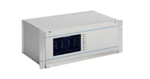
ATN-8694 Microprocessor-based Low-Frequency Low-Voltage Load Shedding Device stabilizes power systems against frequency and voltage drops from power shortage. It performs staged automatic load shedding to restore supply-demand balance.
Communication Mode:Optional: RS-485, CAN bus, Ethernet, IEC 60870-5-103 , IEC 61850
In-house Factory & Technical Team, OEM ODM Custom Electrical Equipment
Send your requirements, we will quote for you within 12 hours
Description
Overview of Low-Frequency Low-Voltage Load Shedding Device
- ATN-8694 Microprocessor-based Low-Frequency Low-Voltage Load Shedding Device stabilizes power systems against frequency and voltage drops from power shortage. It performs staged automatic load shedding to restore supply-demand balance.
- This Power System Emergency Load Shedding Device measures dual-section busbar voltage, equipped with 5 standard and 3 special shedding cycles for underfrequency and undervoltage conditions. Flexible configurable output supports shedding up to 60 load branches, stabilizing grid frequency & voltage and securing reliable power supply.
Technical Features
- Underfrequency load shedding: When active power shortage causes system frequency drop, the device automatically sheds partial loads based on frequency deviation to restore power balance. Equipped with 5 basic stages and 3 special stages.
- Undervoltage load shedding: When reactive power shortage triggers voltage drop, partial loads will be cut off automatically to rebalance power supply and load, with 5 basic and 3 special stages available.
- df/dt and du/dt blocking functions prevent mal-operation induced by short circuit, load rebound and abnormal frequency & voltage fluctuation.
- Busbar split running switch enables setting of split or parallel operation mode for double busbars.
- Modular program design ensures flexible configuration and easy function modification.
- Reliable PT broken line detection avoids false operation of undervoltage protection.
- Max. 21 user-definable binary input channels.
- Programmable output: Trip matrix setting allows flexible relay output selection. Contacts support auto-reset trip type and manual-reset signal type.
- Supports network timing and IRIG-B timing via RS485 port.
- Dual 100M Ethernet ports and one RS485 port, compatible with IEC60870-5-103, 104 and Modbus protocols.
- Stores 16 fault records, sampling up to 13 analog channels at 1ms interval in standard Comtrade format.
- Advanced color touch LCD panel features prolonged service life.
Basic Feature Configuration of Frequency Voltage Emergency Control Relay
- Underfrequency load shedding: Cuts partial loads against frequency drop caused by active power shortage to restore power balance. Configured with 5 basic stages, 3 special stages, 2 accelerated shedding stages and 2&3 combined accelerated shedding stages.
- Accelerated underfrequency shedding: Sheds loads rapidly based on df/dt value when frequency declines sharply. Accelerates stage 2 or stage 2&3 shedding along with stage 1 action to halt frequency collapse.
- Undervoltage load shedding: Removes partial loads to recover normal voltage level under reactive power deficit. Equipped with 5 basic stages, 3 special stages and corresponding accelerated shedding functions.
- Accelerated undervoltage shedding: Fast load shedding by dU/dt criterion curbs rapid voltage drop, prevents voltage collapse and restores voltage within permissible range.
- df/dt and du/dt slip blocking function
- PT broken line blocking and alarm function
- Undervoltage blocking function
- Busbar split operation switch supports split or parallel operation mode
- IRIG-B and SNTP time synchronization
IEC 60255-118-1 Load Shedding Relay Setting Parameters Table
| No. | Setting Name | Range | Unit | Remark |
|---|---|---|---|---|
| 1 | 1st Stage Underfrequency Setting of Bus I | 45~50 | Hz | |
| 2 | 2nd Stage Underfrequency Setting of Bus I | 45~50 | Hz | |
| 3 | 3rd Stage Underfrequency Setting of Bus I | 45~50 | Hz | |
| 4 | 4th Stage Underfrequency Setting of Bus I | 45~50 | Hz | |
| 5 | 5th Stage Underfrequency Setting of Bus I | 45~50 | Hz | |
| 6 | 1st Special Underfrequency Setting of Bus I | 45~50 | Hz | |
| 7 | 2nd Special Underfrequency Setting of Bus I | 45~50 | Hz | |
| 8 | 3rd Special Underfrequency Setting of Bus I | 45~50 | Hz | |
| 9 | df/dt Setting for 2-stage Accelerated Shedding of Bus I | 0.20~20 | Hz/s | |
| 10 | df/dt Setting for 2-3 Stage Accelerated Shedding of Bus I | 0.20~20 | Hz/s | |
| 11 | Frequency Variation Rate Block Setting of Bus I | 0.20~20 | Hz/s | |
| 12 | 1st Stage Underfrequency Time Delay of Bus I | 0.05~10 | s | |
| 13 | 2nd Stage Underfrequency Time Delay of Bus I | 0.05~10 | s | |
| 14 | 3rd Stage Underfrequency Time Delay of Bus I | 0.05~10 | s | |
| 15 | 4th Stage Underfrequency Time Delay of Bus I | 0.05~10 | s | |
| 16 | 5th Stage Underfrequency Time Delay of Bus I | 0.05~10 | s | |
| 17 | 1st Special Underfrequency Time Delay of Bus I | 0.05~10 | s | |
| 18 | 2nd Special Underfrequency Time Delay of Bus I | 0.05~10 | s | |
| 19 | 3rd Special Underfrequency Time Delay of Bus I | 0.05~10 | s | |
| 20 | 2-stage Accelerated Underfrequency Delay of Bus I | 0.05~10 | s | |
| 21 | 2-3 Stage Accelerated Underfrequency Delay of Bus I | 0.05~10 | s | |
| 22 | 1st Stage Undervoltage Setting of Bus I | 45~50 | V | |
| 23 | 2nd Stage Undervoltage Setting of Bus I | 45~50 | V | |
| 24 | 3rd Stage Undervoltage Setting of Bus I | 45~50 | V | |
| 25 | 4th Stage Undervoltage Setting of Bus I | 45~50 | V | |
| 26 | 5th Stage Undervoltage Setting of Bus I | 45~50 | V | |
| 27 | 1st Special Undervoltage Setting of Bus I | 45~50 | V | |
| 28 | 2nd Special Undervoltage Setting of Bus I | 45~50 | V | |
| 29 | 3rd Special Undervoltage Setting of Bus I | 45~50 | V | |
| 30 | dU/dt Setting for 2-stage Accelerated Shedding of Bus I | 0.20~20 | V/s | |
| 31 | dU/dt Setting for 2-3 Stage Accelerated Shedding of Bus I | 0.20~20 | V/s | |
| 32 | Voltage Variation Rate Block Setting of Bus I | 0.20~20 | V/s | |
| 33 | 1st Stage Undervoltage Time Delay of Bus I | 0.05~10 | s | |
| 34 | 2nd Stage Undervoltage Time Delay of Bus I | 0.05~10 | s | |
| 35 | 3rd Stage Undervoltage Time Delay of Bus I | 0.05~10 | s | |
| 36 | 4th Stage Undervoltage Time Delay of Bus I | 0.05~10 | s | |
| 37 | 5th Stage Undervoltage Time Delay of Bus I | 0.05~10 | s | |
| 38 | 1st Special Undervoltage Time Delay of Bus I | 0.05~10 | s | |
| 39 | 2nd Special Undervoltage Time Delay of Bus I | 0.05~10 | s | |
| 40 | 3rd Special Undervoltage Time Delay of Bus I | 0.05~10 | s | |
| 41 | 2-stage Accelerated Undervoltage Delay of Bus I | 0.05~10 | s | |
| 42 | 2-3 Stage Accelerated Undervoltage Delay of Bus I | 0.05~10 | s | |
| 43 | 1st Stage Underfrequency Setting of Bus II | 45~50 | Hz | |
| 44 | 2nd Stage Underfrequency Setting of Bus II | 45~50 | Hz | |
| 45 | 3rd Stage Underfrequency Setting of Bus II | 45~50 | Hz | |
| 46 | 4th Stage Underfrequency Setting of Bus II | 45~50 | Hz | |
| 47 | 5th Stage Underfrequency Setting of Bus II | 45~50 | Hz | |
| 48 | 1st Special Underfrequency Setting of Bus II | 45~50 | Hz | |
| 49 | 2nd Special Underfrequency Setting of Bus II | 45~50 | Hz | |
| 50 | 3rd Special Underfrequency Setting of Bus II | 45~50 | Hz | |
| 51 | df/dt Setting for 2-stage Accelerated Shedding of Bus II | 0.20~20 | Hz/s | |
| 52 | df/dt Setting for 2-3 Stage Accelerated Shedding of Bus II | 0.20~20 | Hz/s | |
| 53 | Frequency Variation Rate Block Setting of Bus II | 0.20~20 | Hz/s | |
| 54 | 1st Stage Underfrequency Time Delay of Bus II | 0.05~10 | s | |
| 55 | 2nd Stage Underfrequency Time Delay of Bus II | 0.05~10 | s | |
| 56 | 3rd Stage Underfrequency Time Delay of Bus II | 0.05~10 | s | |
| 57 | 4th Stage Underfrequency Time Delay of Bus II | 0.05~10 | s | |
| 58 | 5th Stage Underfrequency Time Delay of Bus II | 0.05~10 | s | |
| 59 | 1st Special Underfrequency Time Delay of Bus II | 0.05~10 | s | |
| 60 | 2nd Special Underfrequency Time Delay of Bus II | 0.05~10 | s | |
| 61 | 3rd Special Underfrequency Time Delay of Bus II | 0.05~10 | s | |
| 62 | 2-stage Accelerated Underfrequency Delay of Bus II | 0.05~10 | s | |
| 63 | 2-3 Stage Accelerated Underfrequency Delay of Bus II | 0.05~10 | s | |
| 64 | 1st Stage Undervoltage Setting of Bus II | 45~50 | V | |
| 65 | 2nd Stage Undervoltage Setting of Bus II | 45~50 | V | |
| 66 | 3rd Stage Undervoltage Setting of Bus II | 45~50 | V | |
| 67 | 4th Stage Undervoltage Setting of Bus II | 45~50 | V | |
| 68 | 5th Stage Undervoltage Setting of Bus II | 45~50 | V | |
| 69 | 1st Special Undervoltage Setting of Bus II | 45~50 | V | |
| 70 | 2nd Special Undervoltage Setting of Bus II | 45~50 | V | |
| 71 | 3rd Special Undervoltage Setting of Bus II | 45~50 | V | |
| 72 | dU/dt Setting for 2-stage Accelerated Shedding of Bus II | 0.20~20 | V/s | |
| 73 | dU/dt Setting for 2-3 Stage Accelerated Shedding of Bus II | 0.20~20 | V/s | |
| 74 | Voltage Variation Rate Block Setting of Bus II | 0.20~20 | V/s | |
| 75 | 1st Stage Undervoltage Time Delay of Bus II | 0.05~10 | s | |
| 76 | 2nd Stage Undervoltage Time Delay of Bus II | 0.05~10 | s | |
| 77 | 3rd Stage Undervoltage Time Delay of Bus II | 0.05~10 | s | |
| 78 | 4th Stage Undervoltage Time Delay of Bus II | 0.05~10 | s | |
| 79 | 5th Stage Undervoltage Time Delay of Bus II | 0.05~10 | s | |
| 80 | 1st Special Undervoltage Time Delay of Bus II | 0.05~10 | s | |
| 81 | 2nd Special Undervoltage Time Delay of Bus II | 0.05~10 | s | |
| 82 | 3rd Special Undervoltage Time Delay of Bus II | 0.05~10 | s | |
| 83 | 2-stage Accelerated Undervoltage Delay of Bus II | 0.05~10 | s | |
| 84 | 2-3 Stage Accelerated Undervoltage Delay of Bus II | 0.05~10 | s |
FAQ|Under-frequency & Under-voltage Load Shedding Device
Q1:In which projects are UFLS and UVLS relays applied?
A:
Isolated grid systems: including captive power plants, microgrids and island power grids. It rapidly balances local power after disconnection from main grid to prevent blackout.
Weak tie-line systems: remote rural, forest power networks and grid terminals with dense industrial loads, featuring low tie-line capacity and vulnerability to instability.
Critical power supply projects: metallurgy, chemical and other continuous production industries. Load shedding retains core facilities to avoid equipment damage and economic losses.
New energy grid-connected projects: regional grids with high wind and solar penetration, mitigating power imbalance caused by renewable energy output fluctuation.
Q2:What is the core function of this device?
A: It automatically sheds non-essential loads when grid frequency or voltage abnormally declines to stop system collapse and maintain main grid stable operation.
Q3:Which occasions is it applicable to?
A: Widely installed in distribution substations, industrial power stations and isolated small power grids for power system stability control.
Q4:Can parameters be flexibly configured on site?
A: Yes. Frequency, voltage action threshold and delay time are adjustable locally according to practical grid operating requirements.
Q5:Does the equipment support time synchronization?
A: Equipped with IRIG-B and NTP timing interfaces to ensure synchronous action of multi-group load shedding across stations.
2 reviews for Low-Frequency Low-Voltage Load Shedding Device | UFUVLS Relay for Power Grid Stability
Related products


High Quality
Stable performance, reliable design, ensuring safe operation for power system protection and grid stability.
Fast Delivery
Timely delivery to support your urgent orders and project schedules efficiently and professionally at any time.
Best Warranty
Professional Warranty: Reliable after-sales support for stable relay protection and long-term customer satisfaction.
xiao zhang –
This under-frequency & under-voltage load shedding unit boasts precise setting and quick response. It automatically cuts non-critical loads upon grid frequency/voltage drop to prevent system collapse, widely used in substation power grid stability control.
Jack –
Excellent surge withstand capability — passed all site tests.