
-
Leon Zhang Sales Manager
-
Email: sale@relayprotect.com
-
Phone/WhatsApp: +86 13655813266
Five Levels of DCS Control System Architecture
What is a DCS control system and how is it structured?
DCS control system means distributed control system: an architecture that spreads control across plant-floor controllers and concentrates operation at one supervisory station. Five functional levels connect field sensors to plant scheduling over a redundant network, so a failed controller degrades one node instead of stopping the process. Level 0 holds field devices, Level 1 the I/O modules and distributed controllers, Level 2 the operator stations, alarms and historian, Level 3 production management, and Level 4 the business systems. A 300 MW unit can carry 4,000 to 8,000 I/O points; local cabinets cut each analog run to tens of metres. Most process loops execute every 100 to 500 ms, while turbine governing runs under 20 ms. Protection stays in dedicated relays built to IEC 60255-1:2022 with device numbers from ANSI/IEEE C37.2, and safety functions sit outside the DCS under IEC 61511-1:2016. Setting review and quotation within 12 hours, MOQ 1, 7-15 working days.
DCS control system means distributed control system: an architecture that spreads control across plant-floor controllers and concentrates operation at one supervisory station. Five functional levels connect field sensors to plant scheduling over a redundant network, and a failed controller degrades one node instead of stopping the process.
Written by Leon Zhang, protection application engineer. Technical review by the relayprotect.com engineering team, electrical engineer. Last reviewed 2026-10-28.
The architecture is older than most of the equipment running on it. Honeywell shipped TDC 2000 and Yokogawa shipped CENTUM within weeks of each other in 1975. Every generation since has kept the same premise: put the control close to the process, keep the operation in one room. In a power plant the DCS handles boiler, turbine and balance-of-plant loops while protection stays in dedicated relays built to IEC 60255-1:2022, with device numbers fixed by ANSI/IEEE C37.2:2022. Safety instrumented functions sit outside the DCS entirely, per IEC 61511-1:2016. That division of labour is the first thing to understand. A refinery, a thermal power station and a paper mill all run on it.
At a Glance
- A DCS spreads control across plant-floor controllers and concentrates supervision at one operator station.
- Five levels run from field sensors up to plant scheduling; executable control lives at Level 1.
- The first commercial systems shipped in 1975: Honeywell TDC 2000 and Yokogawa CENTUM.
- A failed controller takes down one node, not the plant; redundancy covers the rest.
- Field signals stay 4-20 mA over twisted pair, with HART or Modbus layered on top.
- DCS suits continuous processes, PLCs suit machines, SCADA suits geographically scattered assets.
- Security zones and conduits follow IEC 62443-3-3:2013; safety loops stay separate per IEC 61511-1:2016.
- Quote I/O count, controller redundancy, scan time and historian retention before price.
DCS Control System Architecture: Five Levels from Sensor to Screen
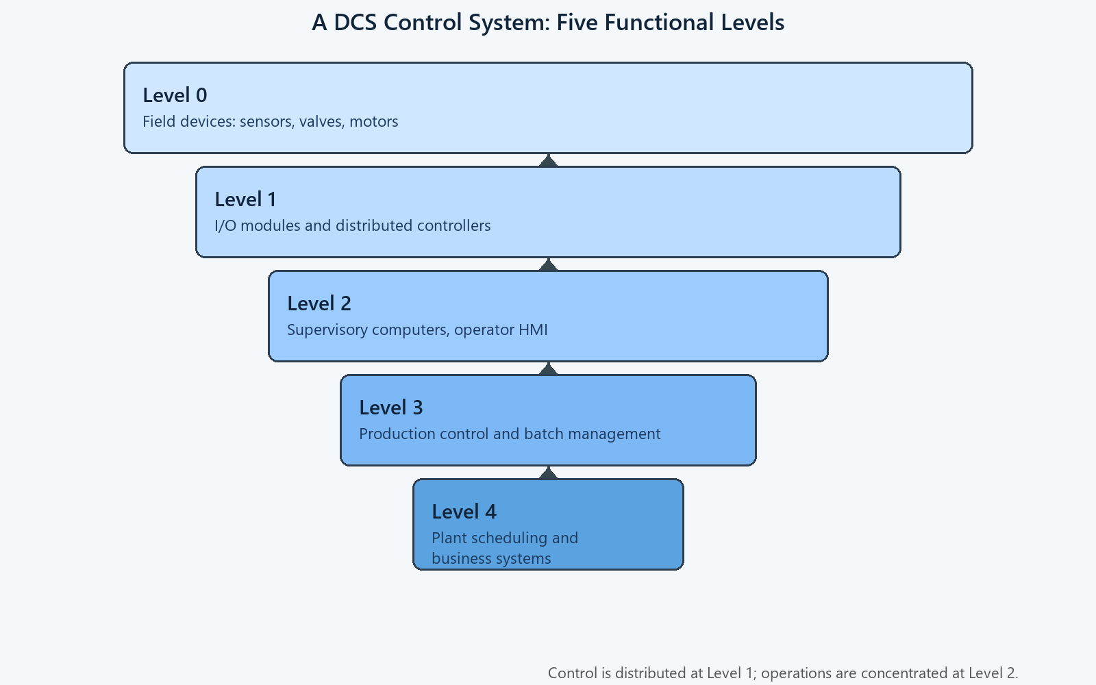
Every dcs control system is drawn as five levels, and the drawing is more than decoration. Level 0 holds the field devices: thermocouples, pressure transmitters on 4-20 mA current loops, control valves with positioners, motor starters. Level 1 holds the I/O modules and the distributed controllers, mounted in cabinets near the process they regulate. Level 2 is the supervisory layer, where operator stations, the alarm system and the historian live. Level 3 manages production: batch recipes, unit coordination, shift reports. Level 4 ties the plant to the business systems that order fuel and sell product.
| Level | What lives there | Typical cycle | What stops if it fails |
|---|---|---|---|
| Level 0 | Sensors, valves, motor starters on 4-20 mA and discrete wiring | Continuous | One measurement or one final element |
| Level 1 | I/O modules and distributed controllers running PID and logic | 50 ms to 500 ms | The loops owned by that controller |
| Level 2 | Operator stations, alarm management, historian | 1 s screens | Supervision, not control |
| Level 3 | Batch management, unit coordination, reports | Minutes | Optimisation and scheduling |
| Level 4 | Planning and business integration | Hours to days | Nothing in the process itself |
Table 1. The five functional levels of a DCS, what each layer runs, and what breaks when it stops.
The levels are functional, not always physical. A single cabinet can hold Level 1 controllers and the network switches that carry Level 2 traffic. Figure 1 shows the hierarchy the way a specification writer should read it: control is distributed at the bottom, information is concentrated at the top, and each boundary is a natural place to draw a security zone.
Selecting a relay for a live project?
Send the system voltage, CT ratio and tripping scheme. Our engineers confirm the model and reply within 12 hours.
How a DCS Distributed Control System Is Wired
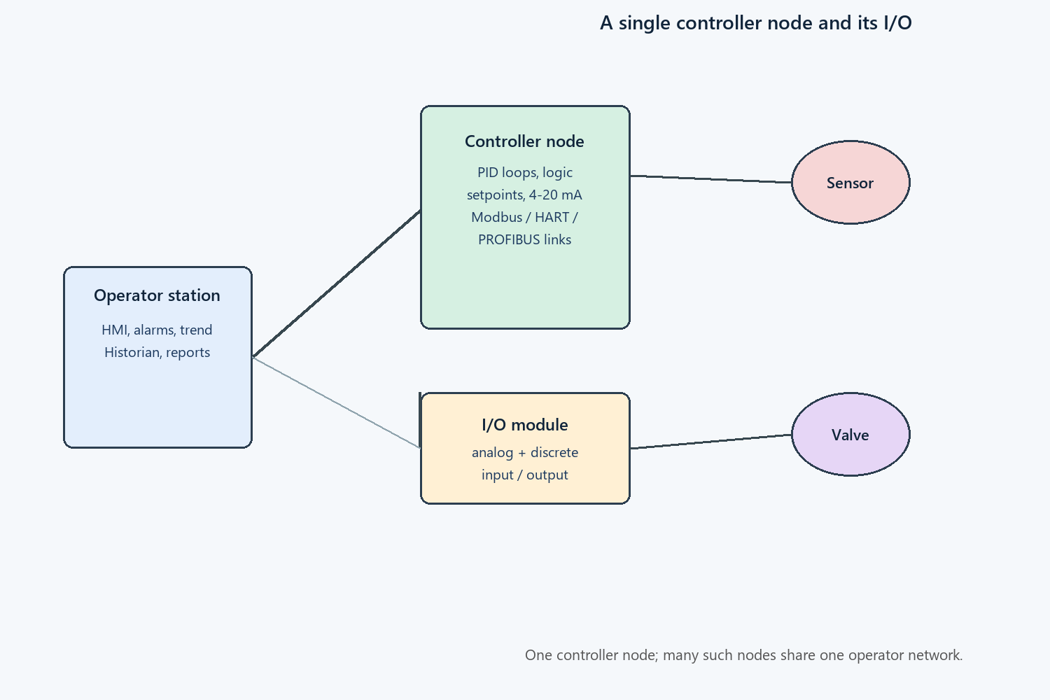
A dcs distributed control system is wired the way it is controlled: locally. Controllers and I/O cabinets sit in electrical rooms close to the motors, valves and instruments they serve, not in one central computer room. A 300 MW unit can carry 4,000 to 8,000 I/O points, and running that many 4-20 mA pairs back to one room would bury the project in copper. Local I/O cuts each analog run to tens of metres and keeps loop response fast, because the signal crosses two cabinets instead of half a plant.
Figure 2 walks through one node. The controller receives transmitter signals through its I/O module, executes the PID and interlock logic, and drives the valve. The operator station sits on a different network and only watches. Many such nodes share one redundant operator network, and each node keeps running if that network is cut.
Distance is the design choice. Copper costs money.
The Control Loop, the Scan and the Operator Screen
Inside the controller the work is cyclic. Read the I/O image, execute the control blocks, write the outputs, repeat. Most process loops execute every 100 ms to 500 ms, which is fast for temperature, level and pressure. Turbine governing and compressor anti-surge run in dedicated controllers with cycle times under 20 ms, because those loops misbehave at process speeds. Setpoints come down from the operator station, and the controller keeps executing them even if the link to Level 2 drops.
The operator screen is a window, not the brain. A well-run Level 2 serves one screen update per second across 3,000 to 10,000 live tags, keeps 90 days of events in the alarm system and years of trends in the historian. Alarm rationalisation matters here: an unmanaged system produces more than 150 alarms per operator per hour during a plant upset, and nobody reads the one that matters. The screen only watches.
The loop lives in the controller.
Redundancy: What Fails and What Keeps Running
Redundancy is priced per failure you never see. The standard package pairs two controllers with automatic switchover in under one second, runs two independent networks, and feeds the cabinets from two power sources with battery-backed supplies. Figure 3 shows the arrangement. A primary controller that loses its CPU hands control to the standby with no process trip, and a cut network cable is an event in the log rather than an outage in the field. One cut cable is a log entry. Two cut cables on one route are an outage.

Redundancy has boundaries, and the quotation should state them. Switchover does not cover an I/O card, a transmitter or a severed 4-20 mA pair, and a common mode mistake such as two power feeds from the same switchboard defeats the whole scheme. Availability targets are written as numbers for a reason: a system specified at 99.99 % allows about 53 minutes of downtime per year, and that budget disappears fast if the redundancy has a shared root.
Distributed Control System DCS vs PLC vs SCADA
The three platforms overlap every year, yet the boundaries still hold in practice. A distributed control system dcs package owns a continuous process inside one plant: integrated controller, I/O families, engineering environment and historian from one vendor. PLCs dominate machines and skids, programmed in the five languages of IEC 61131-3:2025. SCADA masters supervise assets scattered across kilometres, polling over wide-area links.
| Line | DCS | PLC | SCADA |
|---|---|---|---|
| Best fit | Continuous process in one plant | Machines, skids, sequential control | Geographically scattered assets |
| Typical scale | 4,000 to 8,000+ I/O points | 50 to 2,000 I/O points | Thousands of remote sites |
| Control locality | Distributed controllers at the process | One controller per machine | Master polls remote RTUs |
| Loop speed | 100 ms to 500 ms standard | 1 ms to 20 ms | Polling cycle in seconds |
| Engineering tool | One integrated vendor environment | Vendor IDE, free choice per machine | Configuration against drivers |
| Failure blast radius | One controller node | One machine | The polled link, not the site |
Table 2. DCS, PLC and SCADA compared on the six lines that decide a project.
Boundaries blur at the edges. Modern PLC families scale into small process plants, and SCADA systems have grown historian functions that rival a DCS. Sizing decisions still come back to two questions: where does the process physically sit, and how fast must the loop react. Answer those and the platform picks itself.
DCS Automation in a Power Plant: Where the Loops Live
DCS automation in a thermal power station divides into four families of loops. Combustion control keeps fuel, air and draft in balance across 40 to 80 PID loops. Feedwater and drum level control runs three-element strategies on drum level, steam flow and feedwater flow. Turbine governing runs in its own fast controller, and the balance of plant, from cooling water to the water treatment skid, fills out the tag database. One operator screen supervises all of it through the Level 2 network shown in Figure 4.

The protection boundary is what makes the arrangement safe. The DCS issues start and stop commands to motor breakers and reads status from the lockout relay 86, but the trip decision itself belongs to the protection relays and their own trip coils. Motor start inrush of six times rated current rides through on a DCS loop, yet a short-circuit trip belongs to the relay, never to the process computer. An interlock in the DCS can prevent a start, yet it must never be the only thing standing between a fault and the busbar. That is what the protection relay panel is for, and the division is audited line by line during commissioning.
Generator-set plants compress the same pattern into one package. Our automation system for power plant generator sets article shows the LCU-level view, where unit control, synchronising and protection coexist in one cubicle line.
Protocols and Standards Behind the Network
Field signals still enter the system as 4-20 mA current loops, with HART layered on top for device diagnostics. Between cabinets the traffic moves over Modbus TCP, PROFIBUS or Foundation Fieldbus, and integration to Level 3 increasingly rides on OPC UA. Controller logic portability is defined by IEC 61131-3:2025, which matters when a migration keeps the I/O but replaces the controllers. The engineering choice to insist on: documented, testable protocol behaviour at every zone boundary, not a promise of driver support.
Security and safety are the two standards that decide tenders. IEC 62443-3-3:2013 grades the system into zones and conduits with seven security levels, and a plant network that mixes control traffic with office traffic fails the first review. IEC 61511-1:2016 keeps safety instrumented functions in separate logic solvers with their own sensors and final elements, proof-tested on a defined interval. Panels that house the controllers follow IEC 61439-2:2020 for the assembly itself. A circuit breaker or a feeder relay on the boundary is engineered to different rules, which is exactly the point.
| Standard | Edition | Coverage |
|---|---|---|
| IEC 61131-3 | 2025 | Controller programming languages and logic portability |
| IEC 62443-3-3 | 2013 | System security requirements and security levels, zones and conduits |
| IEC 61511-1 | 2016 | Safety instrumented systems for the process industry |
| IEC 60255-1 | 2022 | Measuring relays and protection equipment, general requirements |
| ANSI/IEEE C37.2 | 2022 | Device function numbers used on power plant drawings |
| IEC 61439-2 | 2020 | Low-voltage switchgear assemblies housing the controllers |
Table 3. Standards cited in a DCS specification and what each one governs.
How a DCS Control System Fails
Processors are honest; wiring is not. Across commissioning and the first decade of service, the failures that reach the control room follow a short list, and Table 4 ranks them by how often they arrive.
| Symptom | Likely cause | First check |
|---|---|---|
| One tag reads zero or frozen | Failed channel on an I/O card, or a crushed 4-20 mA pair | Measure loop current at the marshalling terminals |
| Intermittent drift on one loop | Ground loop or moisture in a junction box | Insulation test and shield earthing review |
| Controller changeover caused a bump | Redundancy sync fault after a logic download | Compare active and standby checksums |
| Alarm flood during an upset | Unmanaged alarm limits, no rationalisation | Alarm rate audit, then limit review |
| Network storm slows every screen | Broadcast storm or duplicate address on the operator network | Switch port statistics, then segmentation |
| Historian gaps after a power event | Single power feed, UPS battery past end of life | Battery load test, then feed separation |
Table 4. Common DCS field failures, ranked by how often they reach the operator.
Two patterns dominate the call-outs in my own experience. Ground loops appear months after a modification, when a new junction box landed its shield on a different earth bar, and they burn an instrument technician’s week before anyone suspects the earthing. Alarm floods are self-inflicted: limits set during commissioning were never revisited after the first real upset taught the operators to ignore the list.
Most failures are wiring, not processors.
What to Specify Before You Buy
A dcs control system is bought from a specification, and every line left blank is filled by the supplier’s default. Eight lines decide whether the plant you commission is the plant you drew. Ask for nameplate data on every panel.
- I/O count by type, with 15 % spare capacity and spare slots in each cabinet.
- Controller redundancy level, switchover behaviour and what happens to the loops during a changeover.
- Scan time per loop family, stated in milliseconds, not described as fast.
- Network topology, cable routes and the security zones that follow IEC 62443-3-3:2013.
- Historian retention in days, sampling resolution and the export path to Level 3.
- Alarm management targets: alarm rate per operator, shelving rules and rationalisation scope.
- Engineering environment licence model, because seats decide who can actually maintain the system.
- Spares and support commitment, stated as delivery weeks for controller and I/O hardware.
When a DCS Control System Is the Wrong Choice
Not every plant needs an integrated distributed platform, and the price of finding out late is a control system nobody can maintain. Five situations argue for something smaller or different.
- When the process is one machine or one skid: a PLC panel does the same job at a fraction of the engineering cost.
- When the assets are scattered across a region: SCADA over wide-area links is built for that geometry, a DCS is not.
- When nobody on site will maintain it: an integrated platform with no trained engineers becomes a black box within five years.
- When the safety functions were expected to live inside the DCS: that design fails IEC 61511-1:2016 review and restarts the tender.
- When the budget only covers hardware: underspending on engineering tools and training costs more than the controllers it saved.
Conclusion: What the Architecture Buys You
A dcs control system buys one thing above all others: control that keeps running when parts of itself fail. Controllers sit close to the process, the network carries information rather than control, redundancy covers the layers that cannot stop, and protection stays in its own relays where it was tested. Specify the I/O, the redundancy boundaries and the alarm targets in writing, and the platform will outlive the operator stations that watch it.
Get the division of labour right and each layer does a smaller job. Get it wrong and the system will be redesigned during commissioning, at commissioning prices.
Frequently Asked Questions
What does DCS stand for in a control system?
DCS stands for distributed control system. Control functions are spread across multiple controllers installed close to the process, while operator interfaces, alarm management and process monitoring are concentrated at central operator stations connected over a redundant plant network.
How is a DCS different from a PLC?
A PLC controls one machine or one skid and is programmed in the five languages of IEC 61131-3. A DCS controls a continuous process spread over thousands of I/O points, with controller hardware, I/O families, engineering tools and the historian supplied as one integrated package.
When should I choose a DCS instead of SCADA?
Choose a DCS when the assets are all inside one plant fence and the process runs continuously, for example a boiler, a distillation column or a paper machine. Choose SCADA when the monitored assets are geographically scattered, such as substations, pipelines or wellheads linked over slow wide-area channels.
What scan time does a DCS control loop need?
Most process loops execute every 100 ms to 500 ms, which is comfortable for temperature and level control. Faster loops such as turbine governing run in dedicated controllers with cycle times under 20 ms, and discrete interlocks are handled in separate logic with response times under 50 ms.
Can a DCS trip the turbine or the breaker?
Normally no, and that separation is deliberate. Tripping functions sit in safety instrumented systems built to IEC 61511-1:2016 and in protection relays tested to IEC 60255-1:2022, so a DCS fault cannot disable the last line of defence. The DCS reads trip status but does not own the trip coil.
How long does a DCS last before replacement?
Twenty to thirty years is the realistic service range, with controller hardware usually refreshed once and operator stations refreshed two or three times. Budget the migration when spare parts lead times stretch beyond twelve weeks, not when the first controller fails.
Related Reading on This Site
- The PLC controller guide covers the scan cycle and the five IEC 61131-3 languages in depth.
- Our SCADA systems article explains polling, historians and wide-area architectures.
- The relay page covers the electromechanical devices that still own the trip path.
- For the unit-level view, read the automation system for power plant generator sets overview.
- Breaker behaviour at the boundary between control and protection sits in the circuit breaker guide.
Related guides: HMI system · Switch board · Power transformer
Related products: PLC Control Panel for Hydropower and Pumping Stations · SCADA System ATN-400
If the selection has to be checked against your switchboard, send the single-line and the ratings.
About Author

Hello, I'm Leon Zhang. I have 15 years of experience in the power relay protection industry with extensive pre-sales and after-sales project experience. Our company specializes in various complete sets of relay protection and automation equipment. I can assist customers in solving all practical on-site project challenges and provide optimal integrated solutions.
Tell Us Your Requirement



High Quality
Stable performance, reliable design, ensuring safe operation for power system protection and grid stability.
Fast Delivery
Timely delivery to support your urgent orders and project schedules efficiently and professionally at any time.
Best Warranty
Professional Warranty: Reliable after-sales support for stable relay protection and long-term customer satisfaction.